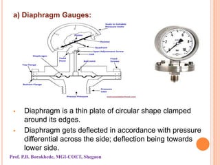
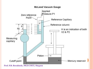
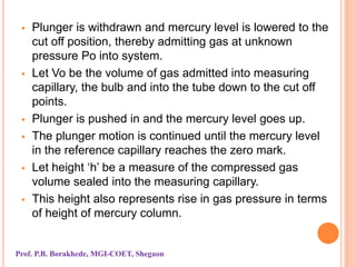
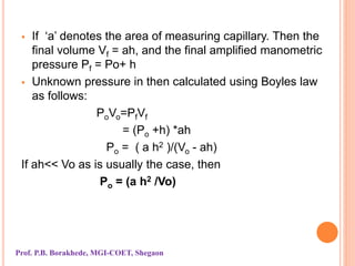
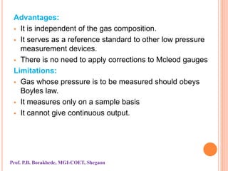
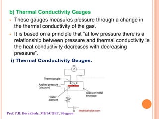
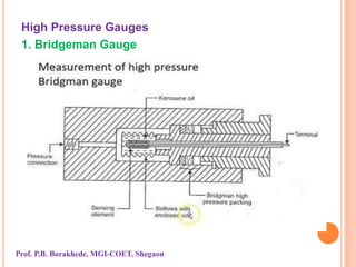
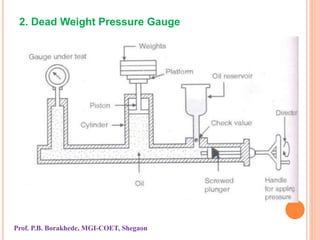
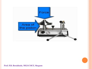
PRESSURE MEASUREMENT
By Prof. P.B. Borakhede
Measurement System
INTRODUCTION
 Pressure measurement is one of the most common of
all the measurements made on systems.
 Along with temperature and flow, pressure
measurements are extensively used in industry,
laboratories and many other fields for a wide variety of
purposes.
 Pressure may be defined as action of a force against
some opposite force.
 There are a wide varieties of pressure measuring
methods and devices which we will discuss.
 Pressure measurement gauges are divided into
following
1. Mechanical Gauges
2. Low pressure Gauges
3. High Pressure Gauges
1. Mechanical Gauges:
Mechanical gauges are sub divided into following:
a) Manometers
b) Bourdon tube pressure gauges
c) Diaphragm gauges
d) Bellow pressure gauges
Prof. P.B. Borakhede, MGI-COET, Shegaon
a) Diaphragm Gauges:
 Diaphragm is a thin plate of circular shape clamped
around its edges.
 Diaphragm gets deflected in accordance with pressure
differential across the side; deflection being towards
lower side.
Prof. P.B. Borakhede, MGI-COET, Shegaon
b) Bellow Pressure Gauge
 The bellow is longitudinally
expansible and collapsible member
consisting of several convolutions
or folds.
 Material selection is generally based
on considerations like strength or
the pressure range, hysteresis and fatigue,
corrosiveness of the bellows
environment, ease of fabrication etc.
 Most common material chosen for
bellows fabrication are: trumpet brass,
stainless steel, phosphor bronze and
beryllium copper.
Prof. P.B. Borakhede, MGI-COET, Shegaon
 The unit is very sensitive; changes of pressure of vacuum
causing a proportional change in the effective length.
 Pressure is applied to one side of the bellows and
resulting deflection is counter balanced by a spring.
 By suitable linkages, bellows displacement is magnified
and the gauge pressure is indicated by a pointer on
scale.
 Axial movement, also called stroke, corresponding to
elastic deformation can be increased by increasing
number of convolutions.
Prof. P.B. Borakhede, MGI-COET, Shegaon
Advantages:
 Simple and rugged construction
 Good for low to moderate pressures
 Available for gauge, differential and absolute pressure
measurements
 Moderate cost
Limitations:
 Greater hysteresis and zero shift problems
 Unsuitable for transient measurements due to a longer
relative motion and mass
 Needs spring for accurate characterization
 Requires compensation for ambient temperature
changes.
Prof. P.B. Borakhede, MGI-COET, Shegaon
2. Low Pressure Gauges
 Pressure less than 1 mm of mercury are considered to be
low pressures, and expressed by torr or micron.
 One torr is a pressure equivalent to 1 mm of Hg at
standard conditions; one micron is 10-3 torr.
 Term vacuum refers to any pressure bellow atmosphere
(760mm Hg).
 This pressure region is divided into five segments:
Low vacuum 760 torr to 25 torr
Medium vacuum 25 torr to 10-3 torr.
High vacuum to 10-6 torr to 10-9 torr.
Ultra high vacuum 10-9 torr and beyond.
Prof. P.B. Borakhede, MGI-COET, Shegaon
Low pressure measurement devices are
a) Mcleod Gauge
b) Thermocouple gauge
c) Ionisation gauge
d) Pirani Vaccum gauge
a) Mcleod Gauge
 The unit comprises a system of glass tubings in which
a known volume of gas at unknown pressure is
trapped and then isothermally compressed by a rising
mercury column.
 This amplifies unknown pressure and allows its
measurement by convnetional manometric means.
 Its operation involves following steps.
Prof. P.B. Borakhede, MGI-COET, Shegaon
 Plunger is withdrawn and mercury level is lowered to the
cut off position, thereby admitting gas at unknown
pressure Po into system.
 Let Vo be the volume of gas admitted into measuring
capillary, the bulb and into the tube down to the cut off
points.
 Plunger is pushed in and the mercury level goes up.
 The plunger motion is continued until the mercury level
in the reference capillary reaches the zero mark.
 Let height ‘h’ be a measure of the compressed gas
volume sealed into the measuring capillary.
 This height also represents rise in gas pressure in terms
of height of mercury column.
Prof. P.B. Borakhede, MGI-COET, Shegaon
 If ‘a’ denotes the area of measuring capillary. Then the
final volume Vf = ah, and the final amplified manometric
pressure Pf = Po+ h
 Unknown pressure in then calculated using Boyles law
as follows:
PoVo=PfVf
= (Po +h) *ah
Po = ( a h2 )/(Vo - ah)
If ah<< Vo as is usually the case, then
Po = (a h2 /Vo)
Prof. P.B. Borakhede, MGI-COET, Shegaon
Advantages:
 It is independent of the gas composition.
 It serves as a reference standard to other low pressure
measurement devices.
 There is no need to apply corrections to Mcleod gauges
Limitations:
 Gas whose pressure is to be measured should obeys
Boyles law.
 It measures only on a sample basis
 It cannot give continuous output.
Prof. P.B. Borakhede, MGI-COET, Shegaon
b) Thermal Conductivity Gauges
 These gauges measures pressure through a change in
the thermal conductivity of the gas.
 It is based on a principle that “at low pressure there is a
relationship between pressure and thermal conductivity ie
the heat conductivity decreases with decreasing
pressure”.
i) Thermal Conductivity Gauges:
Prof. P.B. Borakhede, MGI-COET, Shegaon
 In this gauge the heater element and a thermocouple
welded to it are enclosed in a metal or glass envelope.
 This envelope communicates with the vacuum system
whose pressure is to be measured.
 The element is supplied with a constant electric energy
and its temperature (which is function of the heat loss and
hence thermal conductivity or pressure of the surrounding
gas) is measured by the thermocouple.
 The voltage measuring instrument can be directly
calibrated to read the pressure of the gas.
 Thermocouple gauges of one type or another are available
to measure in the range 10-4 to 1 torr.
 These gauges have following advantages and limitations.
Prof. P.B. Borakhede, MGI-COET, Shegaon
Advantages:
 Rugged and inexpensive construction
 Convenient and continuous reading
 No departure from linearity in the range 0.02 to 1 mm of
Hg.
 Possibility o f process control with meter relay
 Possibility of remote reading from system
Limitations:
 Narrow reading range
 Need for individual and frequent calibration for different
gases
 Requires electric power
Prof. P.B. Borakhede, MGI-COET, Shegaon
ii) Pirani Vacuum Gauges
 It is a type of thermal conductivity
gauge.
 It is based on a hot metal wire
suspended in a tube that is exposed
to gas pressure media.
 The Pirani gauge measures the vacuum pressure
dependent thermal conductivity from the heated wire to
the surrounding gas.
 The heated Pirani sensor filament is typically made of a
thin (<25 µm) Tungsten, Nickel or Platium wire which is
enclosed in glass tube.
 If the gas density is low then then thermal conductivity in
the filament is low.
Prof. P.B. Borakhede, MGI-COET, Shegaon
 The Pirani wire filament is typically operated in a
balanced Wheatstone bridge circuit where one leg of the
bridge is the Pirani filament and the other three
elements of the bridge circuit balance and temperature
compensate the circuit.
 At first the bridge is balances.
 A constant current is passed through the filament in the
pirani gauge chamber. Due to this current, the filament
gets heated and assumes a resistance which is
measured using the bridge.
 Now the pressure source to be measured (applied
pressure) is connected to the pirani gauge chamber.
 Due to the applied pressure the density of the
surrounding of the pirani gauge filament changes.
Prof. P.B. Borakhede, MGI-COET, Shegaon
 Due to the applied pressure the density of the
surrounding of the pirani gauge filament changes.
 Due to this change in density of the surrounding of the
filament its conductivity changes causing the
temperature of the filament to change.
 When the temperature of the filament changes, the
resistance of the filament also changes.
 Now the change in resistance of the filament is
determined using the bridge.
 This change in resistance of the pirani gauge filament
becomes a measure of the applied pressure when
calibrated.
 Used to measure low vacuum and ultra high vacuum
pressures.
Prof. P.B. Borakhede, MGI-COET, Shegaon
Advantages of Pirani gauge
 It covers range form about 10-5 to 1 torr.
 They are rugged and inexpensive
 Give accurate results
 Good response to pressure changes.
 Relation between pressure and resistance is linear for
the range of use.
 Readings can be taken from a distance.
Limitations of Pirani gauge
 Pirani gauge must be checked frequently.
 Pirani gauge must be calibrated from different gases.
 Electric power is a must for its operation.
Prof. P.B. Borakhede, MGI-COET, Shegaon
c) Ionisation Gauge
 The hot filament ionisation gauge consists of heated
filament( cathod) to furnish electrons, a grid and an
anode plate.
 These elements are enclosed in
envelop which communicates with
the vacuum system under test.
 The grid is maintained at positive
potential while anode plate is
maintained at negative potential.
 The cathod is positive ion collector and anode is an
electron collector.
 When electrons are emmited by the heated cathode, high
positive charge on grid accelerates the stream electrons
away from the cathode.
Prof. P.B. Borakhede, MGI-COET, Shegaon
 Because of their speed and relative wide spacing
between the turns of the grid, most of the electrons
continue moving past the grid.
 These electrons collides with gas molecules, thereby
causing ionization of the gas atoms.
 Since the anode plate is maintained at a negative
potential, the positive ions in the space between grid and
anode migrates towards anode and current I1 is produced
in the plate circuit.
 The electrons and negative ions are collected by the grid
and current I2 is produced in the grid circuit.
 The rate of ion production is proportional to the number
of electron available to ionize the gas the and the amount
of gas present.
Prof. P.B. Borakhede, MGI-COET, Shegaon
P= (1/S)(I1 / I2)
Where S is sensitivity.
Advantages:
 Wide pressure range of 10-3 to 10-11 torr.
 Constant sensitivity for a given gas over a wide range of
pressure.
 Possibility of process control and remote indication
 Fast response to pressure changes.
Limitation:
 High cost and complex electrical circuitry
 Calibration varies with gases
 Filament burns out if exposed to air while hot.
 Decomposition of some gases by the hot filament
Prof. P.B. Borakhede, MGI-COET, Shegaon
High Pressure Gauges
1. Bridgeman Gauge
Prof. P.B. Borakhede, MGI-COET, Shegaon
2. Dead Weight Pressure Gauge
Prof. P.B. Borakhede, MGI-COET, Shegaon

Pressure measurement gauges

  • 1.
    PRESSURE MEASUREMENT By Prof.P.B. Borakhede Measurement System
  • 2.
    INTRODUCTION  Pressure measurementis one of the most common of all the measurements made on systems.  Along with temperature and flow, pressure measurements are extensively used in industry, laboratories and many other fields for a wide variety of purposes.  Pressure may be defined as action of a force against some opposite force.  There are a wide varieties of pressure measuring methods and devices which we will discuss.
  • 3.
     Pressure measurementgauges are divided into following 1. Mechanical Gauges 2. Low pressure Gauges 3. High Pressure Gauges 1. Mechanical Gauges: Mechanical gauges are sub divided into following: a) Manometers b) Bourdon tube pressure gauges c) Diaphragm gauges d) Bellow pressure gauges Prof. P.B. Borakhede, MGI-COET, Shegaon
  • 4.
    a) Diaphragm Gauges: Diaphragm is a thin plate of circular shape clamped around its edges.  Diaphragm gets deflected in accordance with pressure differential across the side; deflection being towards lower side. Prof. P.B. Borakhede, MGI-COET, Shegaon
  • 5.
    b) Bellow PressureGauge  The bellow is longitudinally expansible and collapsible member consisting of several convolutions or folds.  Material selection is generally based on considerations like strength or the pressure range, hysteresis and fatigue, corrosiveness of the bellows environment, ease of fabrication etc.  Most common material chosen for bellows fabrication are: trumpet brass, stainless steel, phosphor bronze and beryllium copper. Prof. P.B. Borakhede, MGI-COET, Shegaon
  • 6.
     The unitis very sensitive; changes of pressure of vacuum causing a proportional change in the effective length.  Pressure is applied to one side of the bellows and resulting deflection is counter balanced by a spring.  By suitable linkages, bellows displacement is magnified and the gauge pressure is indicated by a pointer on scale.  Axial movement, also called stroke, corresponding to elastic deformation can be increased by increasing number of convolutions. Prof. P.B. Borakhede, MGI-COET, Shegaon
  • 7.
    Advantages:  Simple andrugged construction  Good for low to moderate pressures  Available for gauge, differential and absolute pressure measurements  Moderate cost Limitations:  Greater hysteresis and zero shift problems  Unsuitable for transient measurements due to a longer relative motion and mass  Needs spring for accurate characterization  Requires compensation for ambient temperature changes. Prof. P.B. Borakhede, MGI-COET, Shegaon
  • 8.
    2. Low PressureGauges  Pressure less than 1 mm of mercury are considered to be low pressures, and expressed by torr or micron.  One torr is a pressure equivalent to 1 mm of Hg at standard conditions; one micron is 10-3 torr.  Term vacuum refers to any pressure bellow atmosphere (760mm Hg).  This pressure region is divided into five segments: Low vacuum 760 torr to 25 torr Medium vacuum 25 torr to 10-3 torr. High vacuum to 10-6 torr to 10-9 torr. Ultra high vacuum 10-9 torr and beyond. Prof. P.B. Borakhede, MGI-COET, Shegaon
  • 9.
    Low pressure measurementdevices are a) Mcleod Gauge b) Thermocouple gauge c) Ionisation gauge d) Pirani Vaccum gauge a) Mcleod Gauge  The unit comprises a system of glass tubings in which a known volume of gas at unknown pressure is trapped and then isothermally compressed by a rising mercury column.  This amplifies unknown pressure and allows its measurement by convnetional manometric means.  Its operation involves following steps. Prof. P.B. Borakhede, MGI-COET, Shegaon
  • 10.
    Prof. P.B. Borakhede,MGI-COET, Shegaon
  • 11.
     Plunger iswithdrawn and mercury level is lowered to the cut off position, thereby admitting gas at unknown pressure Po into system.  Let Vo be the volume of gas admitted into measuring capillary, the bulb and into the tube down to the cut off points.  Plunger is pushed in and the mercury level goes up.  The plunger motion is continued until the mercury level in the reference capillary reaches the zero mark.  Let height ‘h’ be a measure of the compressed gas volume sealed into the measuring capillary.  This height also represents rise in gas pressure in terms of height of mercury column. Prof. P.B. Borakhede, MGI-COET, Shegaon
  • 12.
     If ‘a’denotes the area of measuring capillary. Then the final volume Vf = ah, and the final amplified manometric pressure Pf = Po+ h  Unknown pressure in then calculated using Boyles law as follows: PoVo=PfVf = (Po +h) *ah Po = ( a h2 )/(Vo - ah) If ah<< Vo as is usually the case, then Po = (a h2 /Vo) Prof. P.B. Borakhede, MGI-COET, Shegaon
  • 13.
    Advantages:  It isindependent of the gas composition.  It serves as a reference standard to other low pressure measurement devices.  There is no need to apply corrections to Mcleod gauges Limitations:  Gas whose pressure is to be measured should obeys Boyles law.  It measures only on a sample basis  It cannot give continuous output. Prof. P.B. Borakhede, MGI-COET, Shegaon
  • 14.
    b) Thermal ConductivityGauges  These gauges measures pressure through a change in the thermal conductivity of the gas.  It is based on a principle that “at low pressure there is a relationship between pressure and thermal conductivity ie the heat conductivity decreases with decreasing pressure”. i) Thermal Conductivity Gauges: Prof. P.B. Borakhede, MGI-COET, Shegaon
  • 15.
     In thisgauge the heater element and a thermocouple welded to it are enclosed in a metal or glass envelope.  This envelope communicates with the vacuum system whose pressure is to be measured.  The element is supplied with a constant electric energy and its temperature (which is function of the heat loss and hence thermal conductivity or pressure of the surrounding gas) is measured by the thermocouple.  The voltage measuring instrument can be directly calibrated to read the pressure of the gas.  Thermocouple gauges of one type or another are available to measure in the range 10-4 to 1 torr.  These gauges have following advantages and limitations. Prof. P.B. Borakhede, MGI-COET, Shegaon
  • 16.
    Advantages:  Rugged andinexpensive construction  Convenient and continuous reading  No departure from linearity in the range 0.02 to 1 mm of Hg.  Possibility o f process control with meter relay  Possibility of remote reading from system Limitations:  Narrow reading range  Need for individual and frequent calibration for different gases  Requires electric power Prof. P.B. Borakhede, MGI-COET, Shegaon
  • 17.
    ii) Pirani VacuumGauges  It is a type of thermal conductivity gauge.  It is based on a hot metal wire suspended in a tube that is exposed to gas pressure media.  The Pirani gauge measures the vacuum pressure dependent thermal conductivity from the heated wire to the surrounding gas.  The heated Pirani sensor filament is typically made of a thin (<25 µm) Tungsten, Nickel or Platium wire which is enclosed in glass tube.  If the gas density is low then then thermal conductivity in the filament is low. Prof. P.B. Borakhede, MGI-COET, Shegaon
  • 18.
     The Piraniwire filament is typically operated in a balanced Wheatstone bridge circuit where one leg of the bridge is the Pirani filament and the other three elements of the bridge circuit balance and temperature compensate the circuit.  At first the bridge is balances.  A constant current is passed through the filament in the pirani gauge chamber. Due to this current, the filament gets heated and assumes a resistance which is measured using the bridge.  Now the pressure source to be measured (applied pressure) is connected to the pirani gauge chamber.  Due to the applied pressure the density of the surrounding of the pirani gauge filament changes. Prof. P.B. Borakhede, MGI-COET, Shegaon
  • 19.
     Due tothe applied pressure the density of the surrounding of the pirani gauge filament changes.  Due to this change in density of the surrounding of the filament its conductivity changes causing the temperature of the filament to change.  When the temperature of the filament changes, the resistance of the filament also changes.  Now the change in resistance of the filament is determined using the bridge.  This change in resistance of the pirani gauge filament becomes a measure of the applied pressure when calibrated.  Used to measure low vacuum and ultra high vacuum pressures. Prof. P.B. Borakhede, MGI-COET, Shegaon
  • 20.
    Advantages of Piranigauge  It covers range form about 10-5 to 1 torr.  They are rugged and inexpensive  Give accurate results  Good response to pressure changes.  Relation between pressure and resistance is linear for the range of use.  Readings can be taken from a distance. Limitations of Pirani gauge  Pirani gauge must be checked frequently.  Pirani gauge must be calibrated from different gases.  Electric power is a must for its operation. Prof. P.B. Borakhede, MGI-COET, Shegaon
  • 21.
    c) Ionisation Gauge The hot filament ionisation gauge consists of heated filament( cathod) to furnish electrons, a grid and an anode plate.  These elements are enclosed in envelop which communicates with the vacuum system under test.  The grid is maintained at positive potential while anode plate is maintained at negative potential.  The cathod is positive ion collector and anode is an electron collector.  When electrons are emmited by the heated cathode, high positive charge on grid accelerates the stream electrons away from the cathode. Prof. P.B. Borakhede, MGI-COET, Shegaon
  • 22.
     Because oftheir speed and relative wide spacing between the turns of the grid, most of the electrons continue moving past the grid.  These electrons collides with gas molecules, thereby causing ionization of the gas atoms.  Since the anode plate is maintained at a negative potential, the positive ions in the space between grid and anode migrates towards anode and current I1 is produced in the plate circuit.  The electrons and negative ions are collected by the grid and current I2 is produced in the grid circuit.  The rate of ion production is proportional to the number of electron available to ionize the gas the and the amount of gas present. Prof. P.B. Borakhede, MGI-COET, Shegaon
  • 23.
    P= (1/S)(I1 /I2) Where S is sensitivity. Advantages:  Wide pressure range of 10-3 to 10-11 torr.  Constant sensitivity for a given gas over a wide range of pressure.  Possibility of process control and remote indication  Fast response to pressure changes. Limitation:  High cost and complex electrical circuitry  Calibration varies with gases  Filament burns out if exposed to air while hot.  Decomposition of some gases by the hot filament Prof. P.B. Borakhede, MGI-COET, Shegaon
  • 24.
    High Pressure Gauges 1.Bridgeman Gauge Prof. P.B. Borakhede, MGI-COET, Shegaon
  • 25.
    2. Dead WeightPressure Gauge Prof. P.B. Borakhede, MGI-COET, Shegaon
  • 26.
    Prof. P.B. Borakhede,MGI-COET, Shegaon