Download as PDF, PPTX

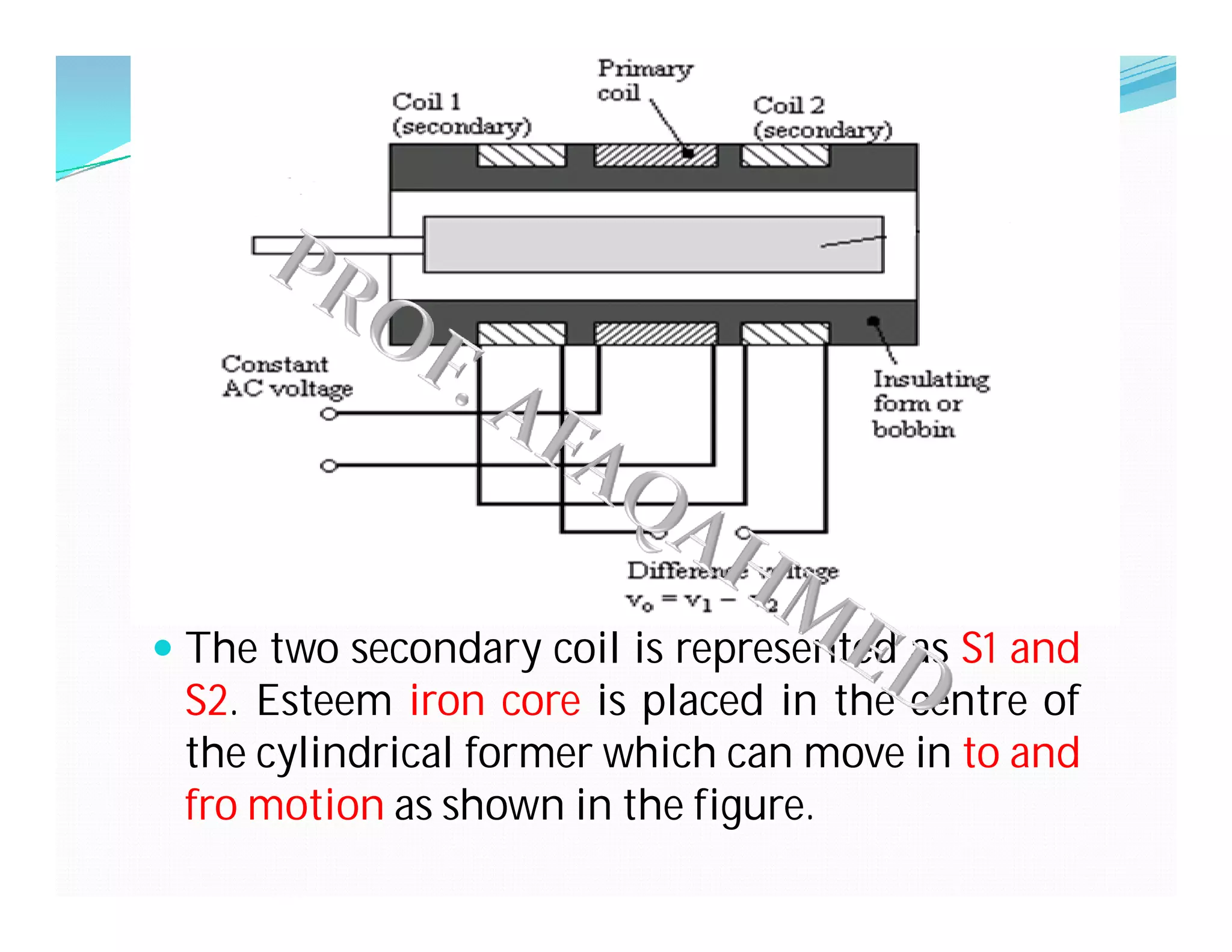
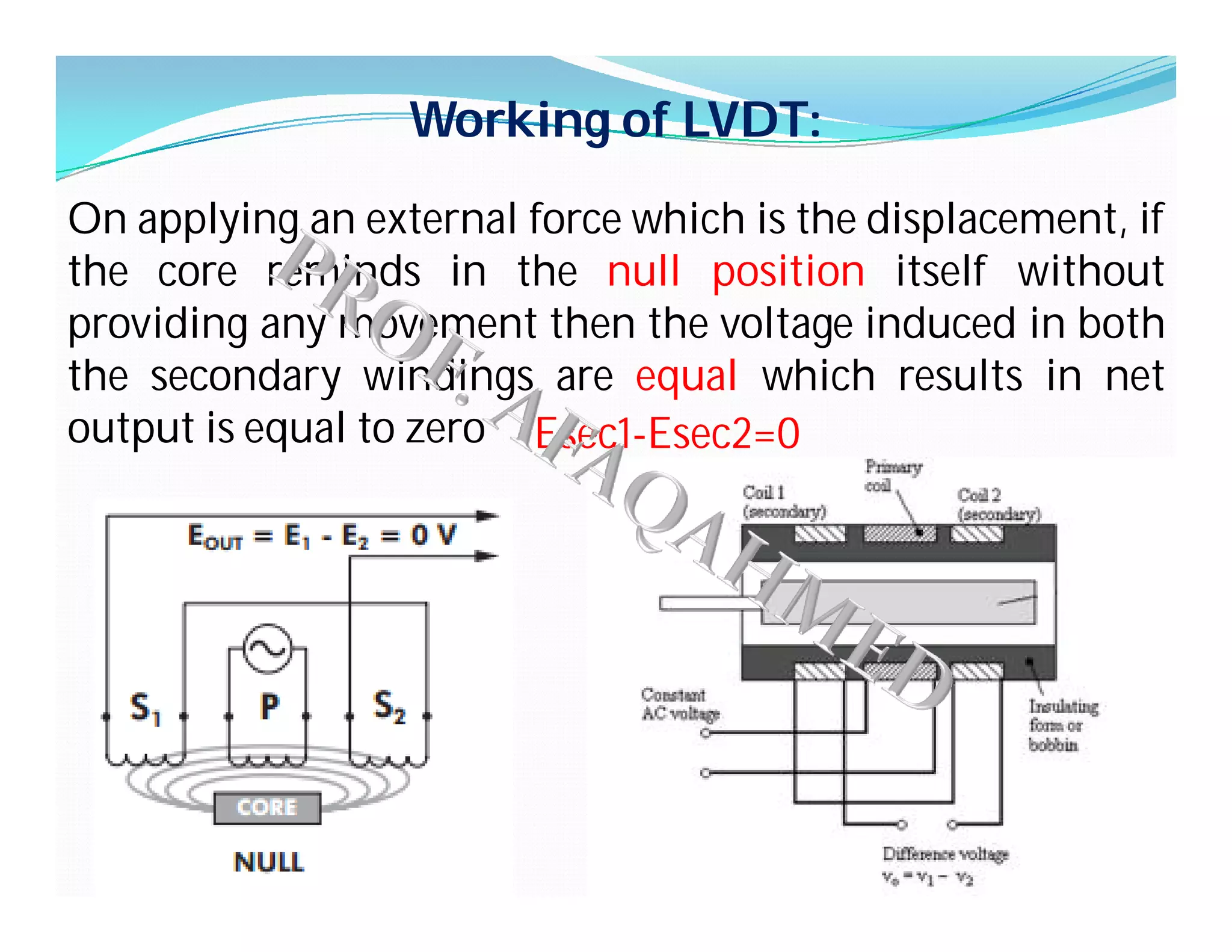
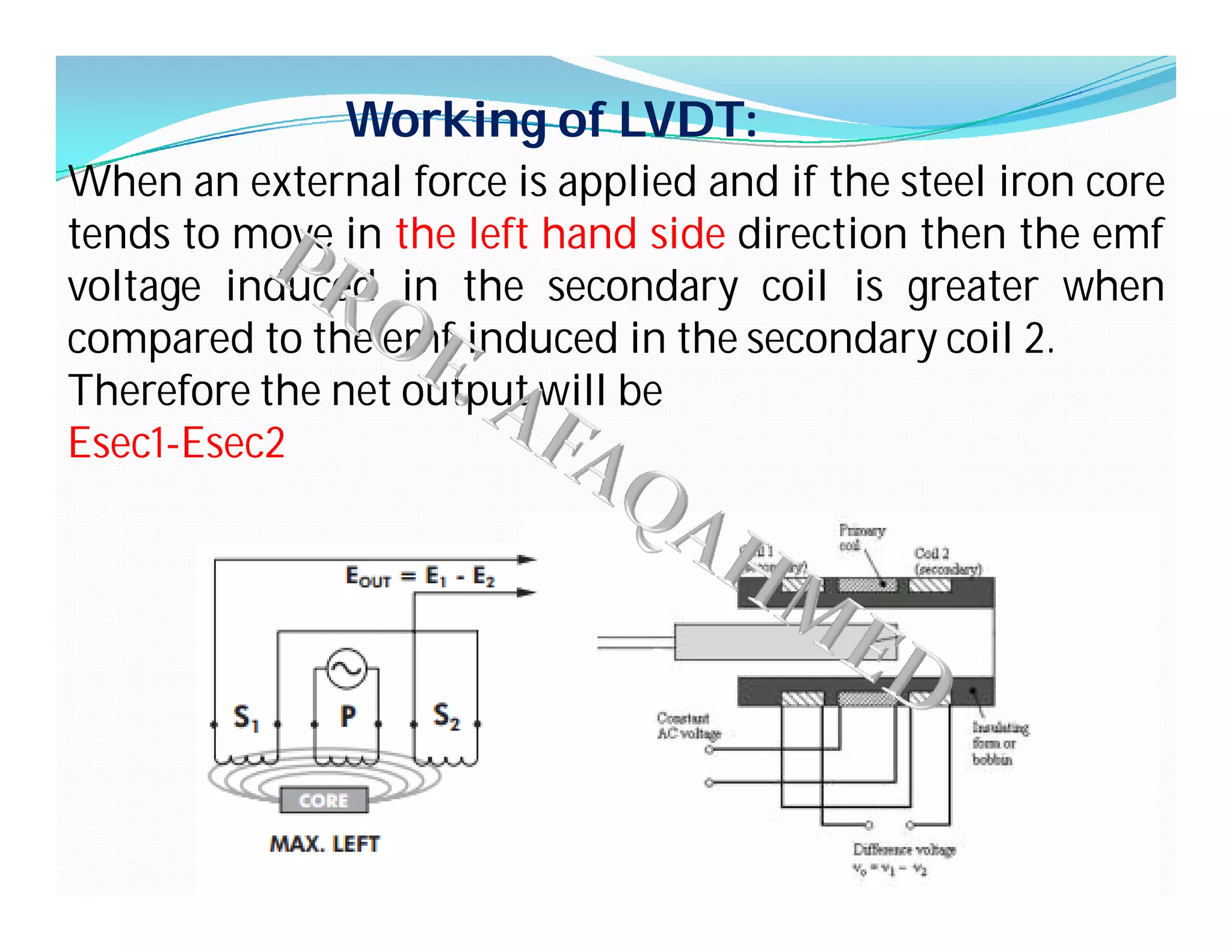
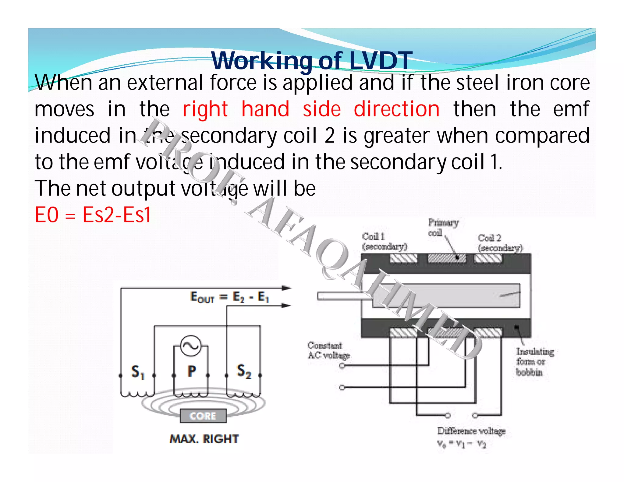
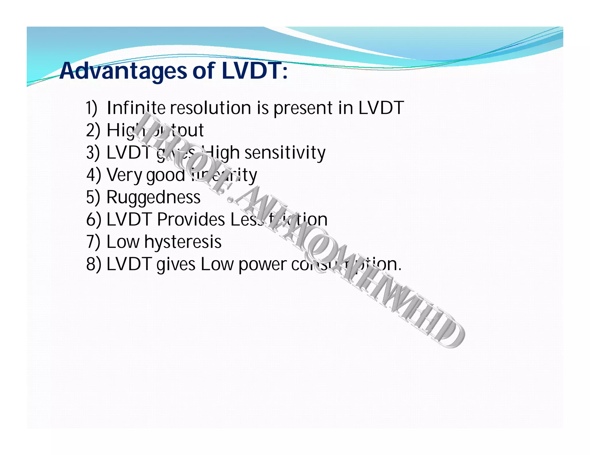

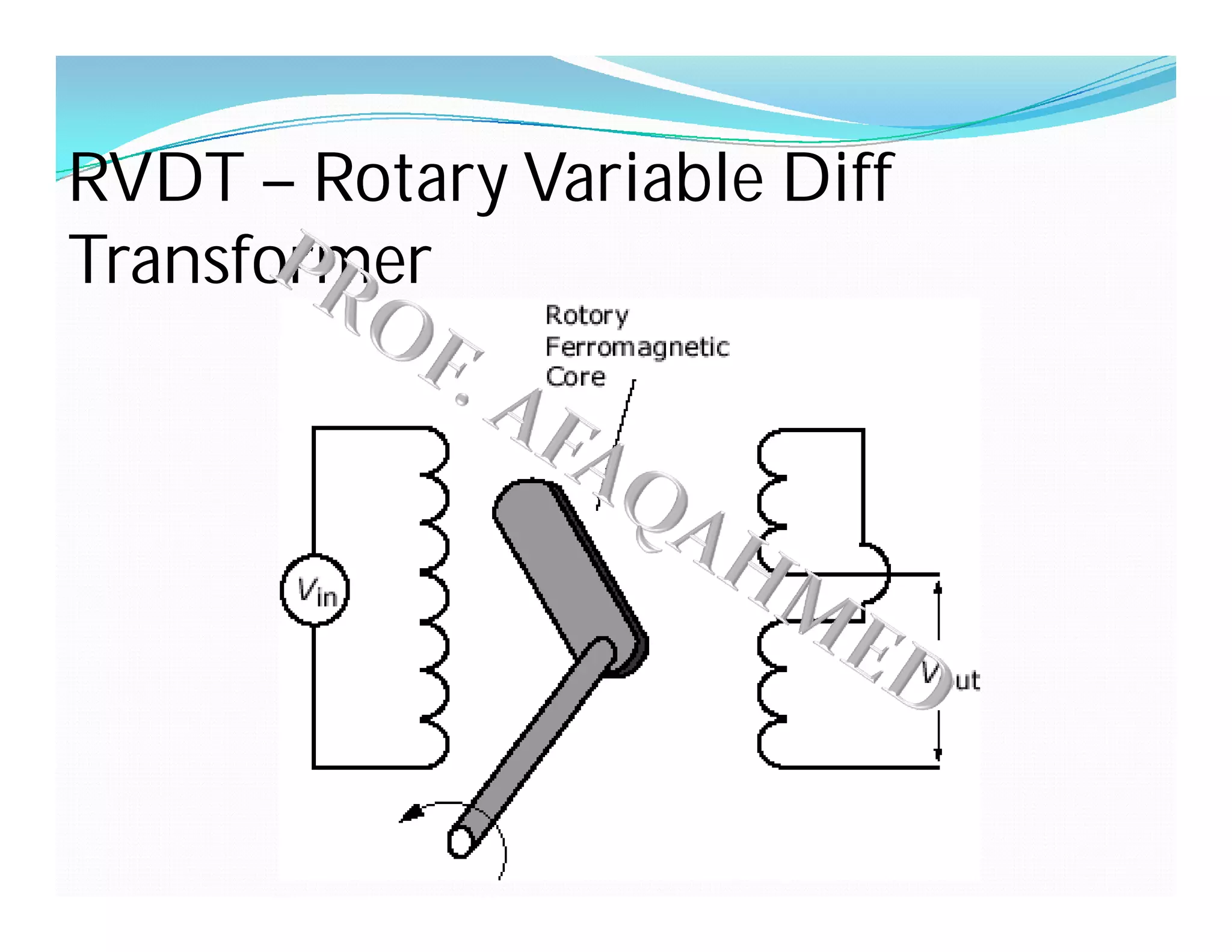
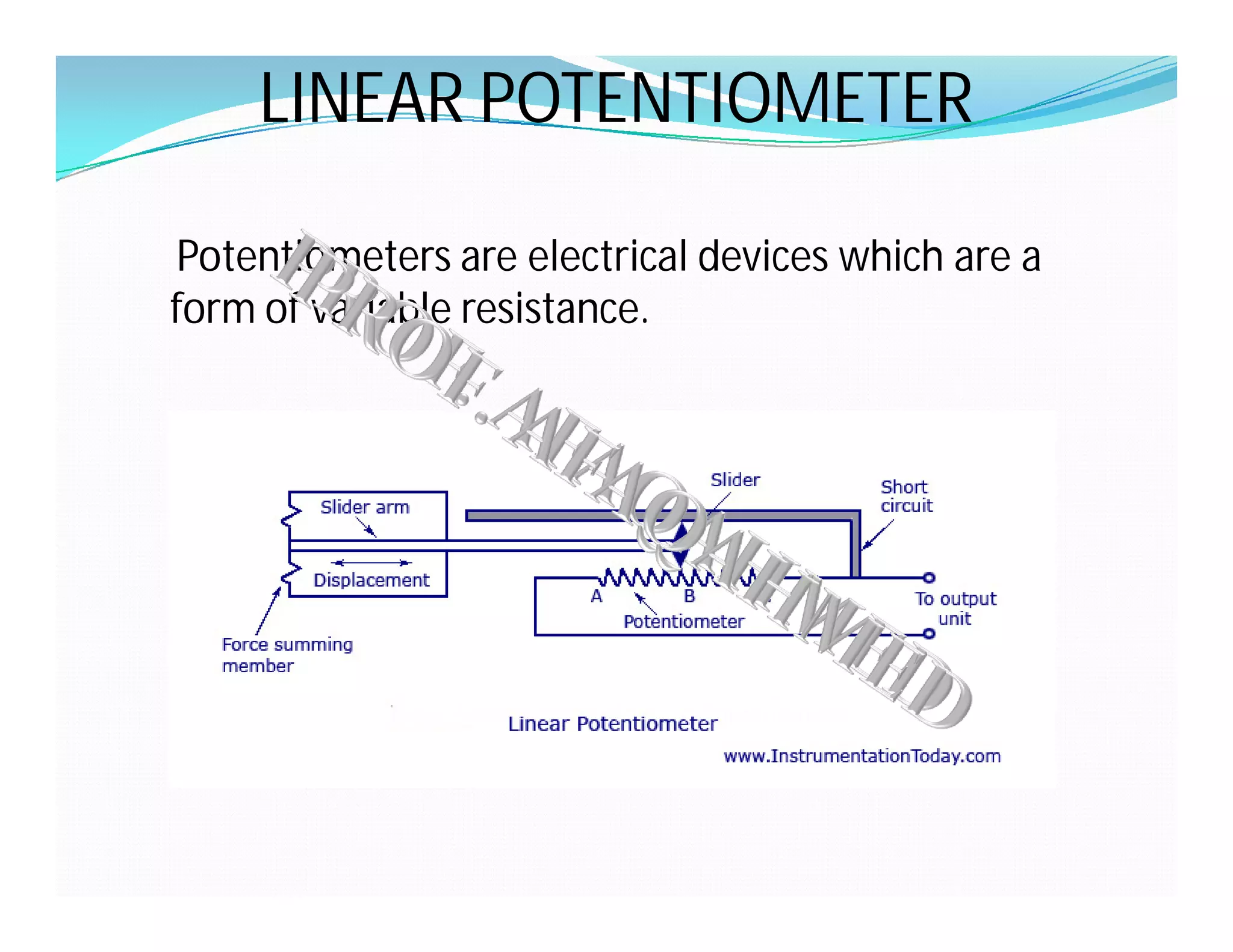
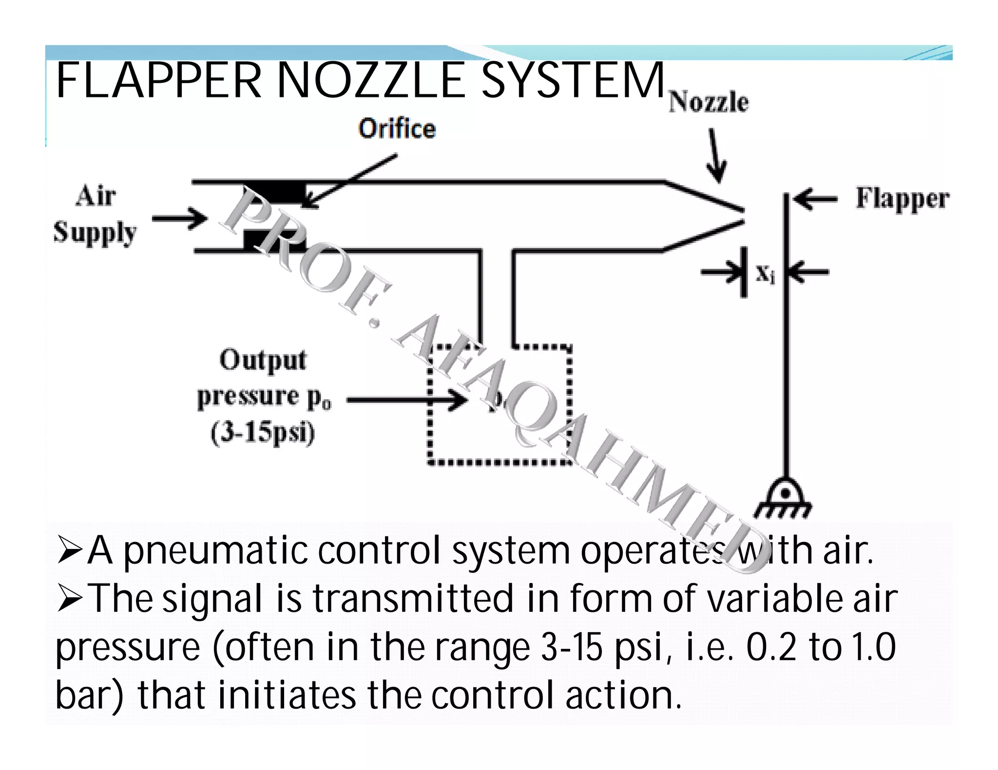

The document provides an overview of linear variable displacement transducers (LVDTs), detailing their principle of operation based on mutual induction, construction with primary and secondary windings, and advantages such as infinite resolution and low power consumption. It also describes related devices such as rotary variable differential transformers (RVDTs) and linear potentiometers, emphasizing their applications in measuring displacement, force, and pressure. Additionally, it briefly covers a flapper nozzle system used in pneumatic control systems.


