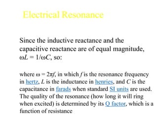
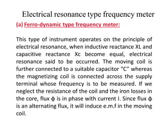
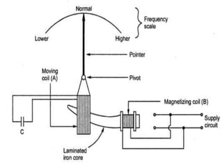
Frequency Meter
Electrical Resonance
Electrical resonance occurs in an electric circuit at a particular
resonance frequency where the imaginary parts of circuit element
impedances or admittances cancel each other. In some circuits this
happens when the impedance between the input and output of the
circuit is almost zero and the transfer function is close to one.
Electrical Resonance
Since the inductive reactance and the
capacitive reactance are of equal magnitude,
ωL = 1/ωC, so:
where ω = 2πf, in which f is the resonance frequency
in hertz, L is the inductance in henries, and C is the
capacitance in farads when standard SI units are used.
The quality of the resonance (how long it will ring
when excited) is determined by its Q factor, which is a
function of resistance
FREQUENCY METERS
Types of frequency meters:
1. Mechanical resonance (reed) type frequency meter
2. Electrical resonance type frequency meter
a) Ferro-dynamic type frequency meter
b)Electro-dynamometer type frequency meter
3. Weston frequency meter
4. Ratiometer type frequency meter
5. Saturable core type frequency meter
Electrical resonance type frequency meter
(a) Ferro-dynamic type frequency meter:
This type of instrument operates on the principle of
electrical resonance, when inductive reactance XL and
capacitive reactance Xc become equal, electrical
resonance said to be occurred. The moving coil is
further connected to a suitable capacitor “C” whereas
the magnetizing coil is connected across the supply
terminal whose frequency is to be measured. If we
neglect the resistance of the coil and the iron losses in
the core, flux ɸ is in phase with current I. Since flux ɸ
is an alternating flux, it will induce e.m.f in the moving
coil.
Construction
Magnetizing Coil
- Consists of a fixed coil called magnetizing coil, which is
connected across the supply whose frequency is to be measured. It is
mounted on a laminated iron core
Iron core
Cross section of iron core varies gradually over the length , being
maximum near the end where magnetizing coil is mounted and
minimum at the other end.
Moving Coil
Moving coil is pivoted over the iron core
A pointer is attached to moving coil
Terminals of moving coil are connected to a suitable capacitor C
No supply for controlling force
Principle of Operation
Magnetizing coil carries a current I and produces flux f in phase with
current I. Flux f induces emf E in the moving coil lagging behind it by 90o.
Emf E circulates current Im in the moving coil. Phase of current Im
depends upon inductance L of the moving coil and capacitance C.
Principle of Operation..
Vector Diagram
Circuit of moving coil is inductive & therefore current Im lags
behind emf E by an angle a. The torque acting on the moving
coil is,
Td is proportional to Im I cos (90o + a)
Circuit of moving coil is capacitive & therefore current Im
leads emf E by an angle b. The torque acting on the moving
coil is,
Td =k Im I cos (90o - b)
Inductive reactance of the circuit of moving coil is equal to its
capacitive reactance & therefore current Im is in phase with
emf E. The torque acting on the moving coil is,
Td =k Im I cos 90o = 0
Principle of Operation……
 At normal frequency ,At this position, inductive
reactance is equal to the capacitive
reactance.Position of the moving coil is at mean
position
 Suppose the frequency increases above its normal
value then, XL > XC & therefore torque is produced.
This torque pulls the moving coil to an equilibrium
position i.e., moving coil deflects towards the
section of iron core having minimum cross section.
So inductive reactance decreases and moving coil
comes to rest at a position where XL = XC.
Principle of Operation……
• Suppose the frequency decreases below its normal value then, XL
< XC & therefore torque is produced. This torque pulls the moving coil to
an equilibrium position i.e., moving coil deflects towards the section of
iron core having maximum cross section. So inductive reactance
increases and moving coil comes to rest at a position where XL = XC.

Frequency Meter : Working principle

  • 1.
  • 2.
    Electrical Resonance Electrical resonanceoccurs in an electric circuit at a particular resonance frequency where the imaginary parts of circuit element impedances or admittances cancel each other. In some circuits this happens when the impedance between the input and output of the circuit is almost zero and the transfer function is close to one.
  • 3.
    Electrical Resonance Since theinductive reactance and the capacitive reactance are of equal magnitude, ωL = 1/ωC, so: where ω = 2πf, in which f is the resonance frequency in hertz, L is the inductance in henries, and C is the capacitance in farads when standard SI units are used. The quality of the resonance (how long it will ring when excited) is determined by its Q factor, which is a function of resistance
  • 4.
    FREQUENCY METERS Types offrequency meters: 1. Mechanical resonance (reed) type frequency meter 2. Electrical resonance type frequency meter a) Ferro-dynamic type frequency meter b)Electro-dynamometer type frequency meter 3. Weston frequency meter 4. Ratiometer type frequency meter 5. Saturable core type frequency meter
  • 5.
    Electrical resonance typefrequency meter (a) Ferro-dynamic type frequency meter: This type of instrument operates on the principle of electrical resonance, when inductive reactance XL and capacitive reactance Xc become equal, electrical resonance said to be occurred. The moving coil is further connected to a suitable capacitor “C” whereas the magnetizing coil is connected across the supply terminal whose frequency is to be measured. If we neglect the resistance of the coil and the iron losses in the core, flux ɸ is in phase with current I. Since flux ɸ is an alternating flux, it will induce e.m.f in the moving coil.
  • 6.
    Construction Magnetizing Coil - Consistsof a fixed coil called magnetizing coil, which is connected across the supply whose frequency is to be measured. It is mounted on a laminated iron core Iron core Cross section of iron core varies gradually over the length , being maximum near the end where magnetizing coil is mounted and minimum at the other end. Moving Coil Moving coil is pivoted over the iron core A pointer is attached to moving coil Terminals of moving coil are connected to a suitable capacitor C No supply for controlling force
  • 7.
    Principle of Operation Magnetizingcoil carries a current I and produces flux f in phase with current I. Flux f induces emf E in the moving coil lagging behind it by 90o. Emf E circulates current Im in the moving coil. Phase of current Im depends upon inductance L of the moving coil and capacitance C.
  • 8.
  • 9.
  • 10.
    Circuit of movingcoil is inductive & therefore current Im lags behind emf E by an angle a. The torque acting on the moving coil is, Td is proportional to Im I cos (90o + a) Circuit of moving coil is capacitive & therefore current Im leads emf E by an angle b. The torque acting on the moving coil is, Td =k Im I cos (90o - b) Inductive reactance of the circuit of moving coil is equal to its capacitive reactance & therefore current Im is in phase with emf E. The torque acting on the moving coil is, Td =k Im I cos 90o = 0 Principle of Operation……
  • 11.
    Principle of Operation…… At normal frequency ,At this position, inductive reactance is equal to the capacitive reactance.Position of the moving coil is at mean position  Suppose the frequency increases above its normal value then, XL > XC & therefore torque is produced. This torque pulls the moving coil to an equilibrium position i.e., moving coil deflects towards the section of iron core having minimum cross section. So inductive reactance decreases and moving coil comes to rest at a position where XL = XC.
  • 12.
    Principle of Operation…… •Suppose the frequency decreases below its normal value then, XL < XC & therefore torque is produced. This torque pulls the moving coil to an equilibrium position i.e., moving coil deflects towards the section of iron core having maximum cross section. So inductive reactance increases and moving coil comes to rest at a position where XL = XC.