Download to read offline

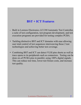
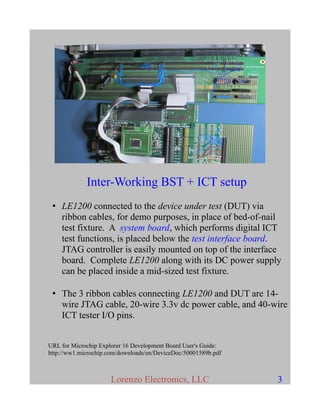


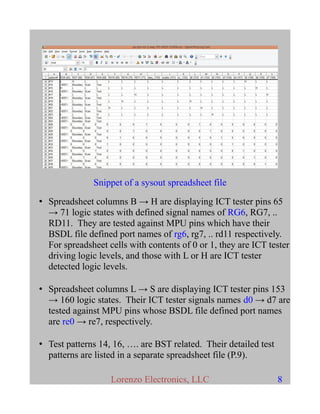


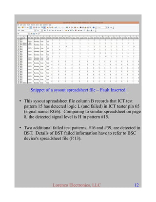

This document describes using an automatic test controller called the LE1200 to perform both boundary scan testing (BST) and in-circuit testing (ICT) on a PIC32 microcontroller-based development board. The LE1200 is connected to the board via ribbon cables and can interleave BST and ICT test patterns to thoroughly test the board and its connections. Sample test result files are shown, with faults correctly detected when a pin on the microcontroller is shorted to ground during testing.