Download as PDF, PPTX

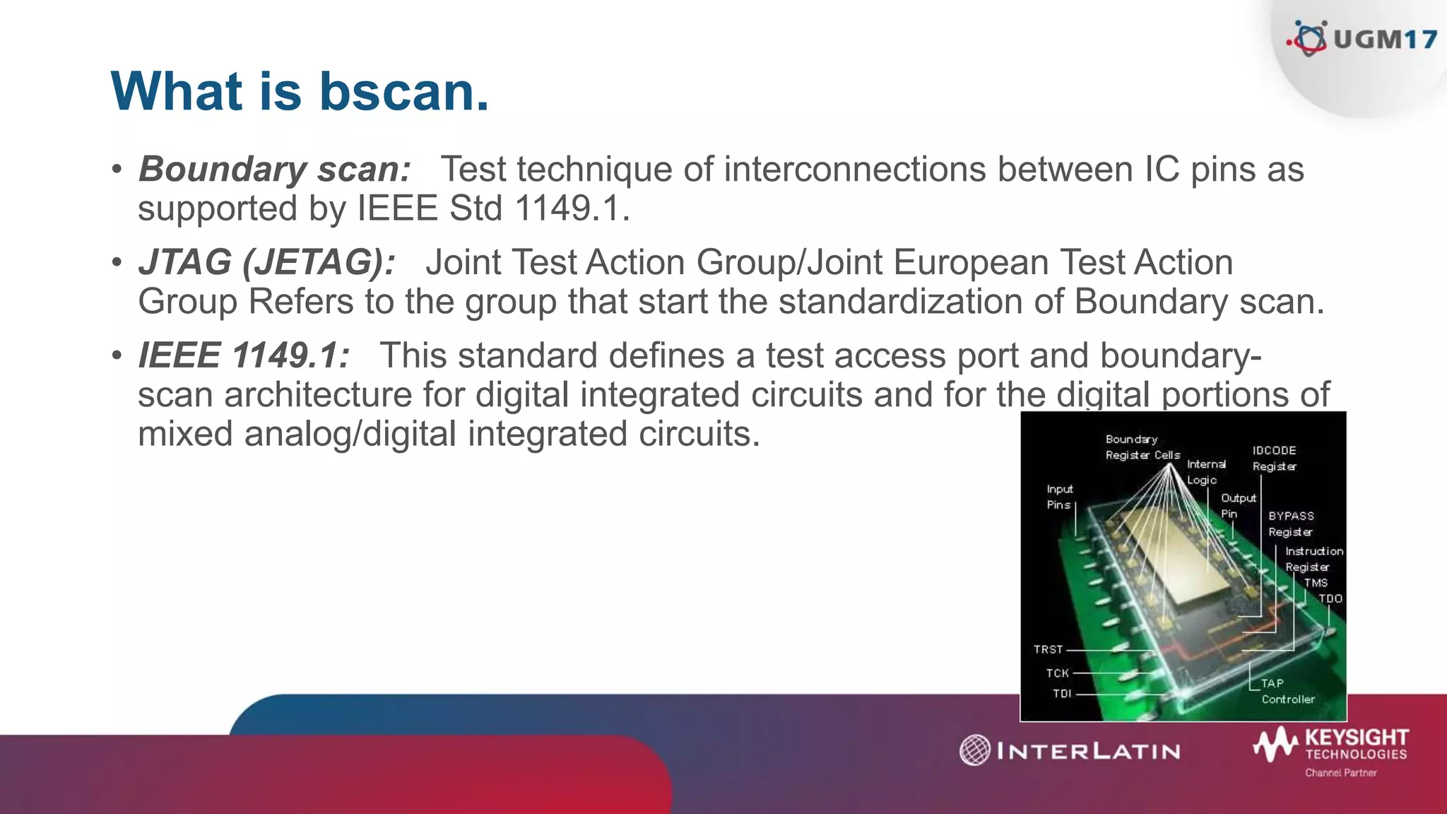
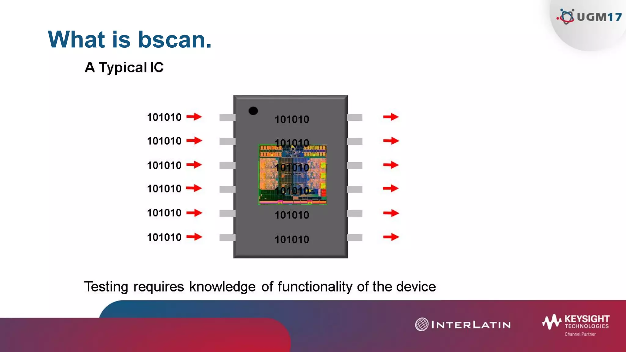
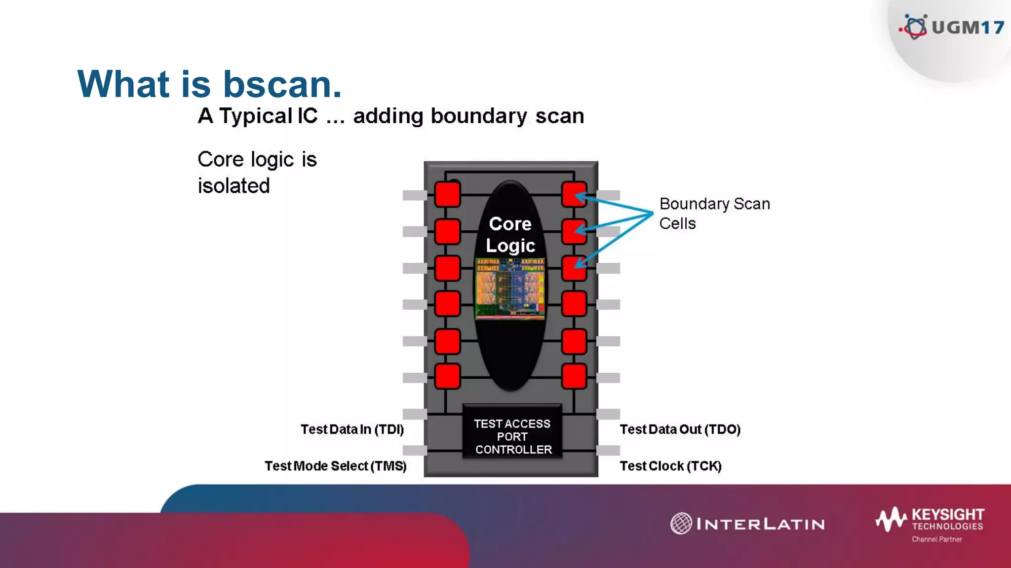
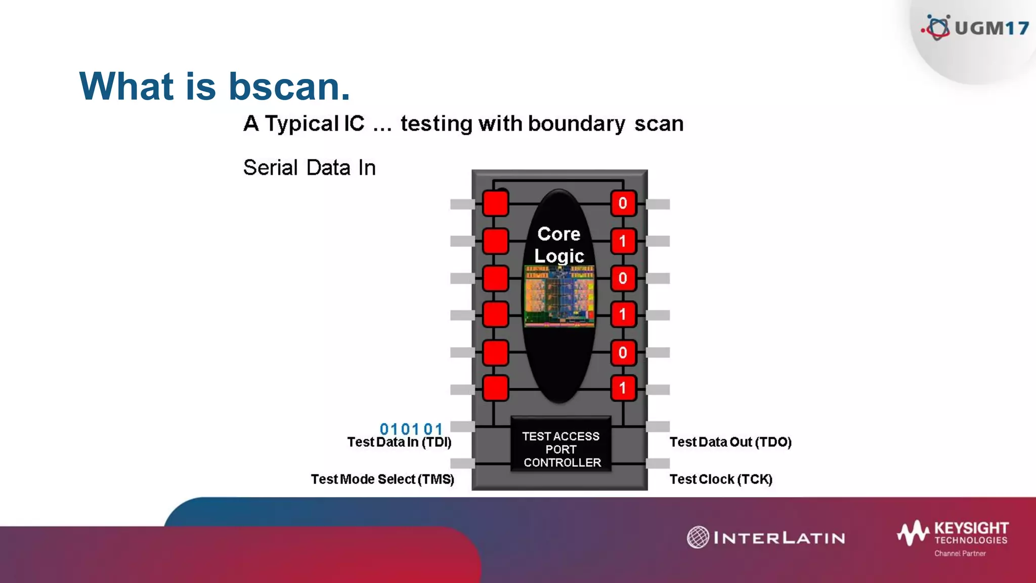
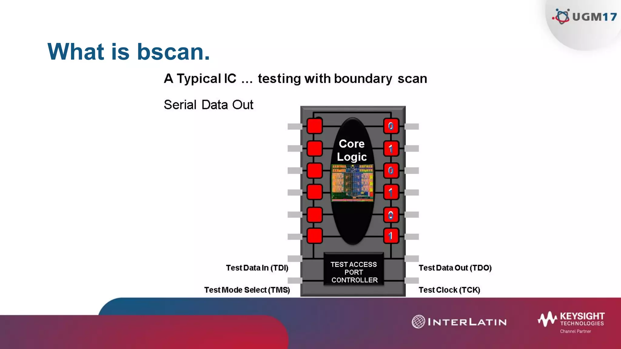
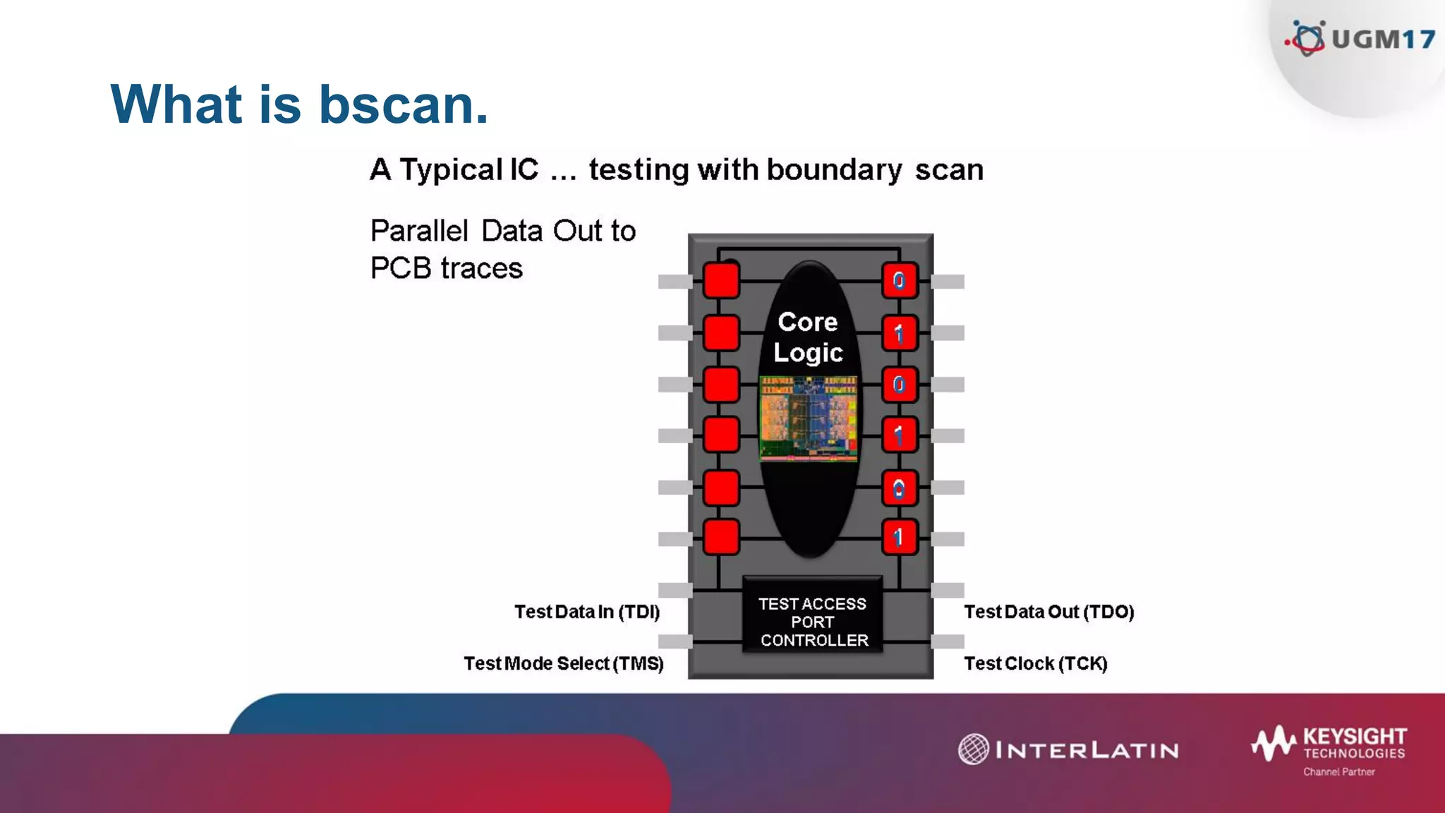
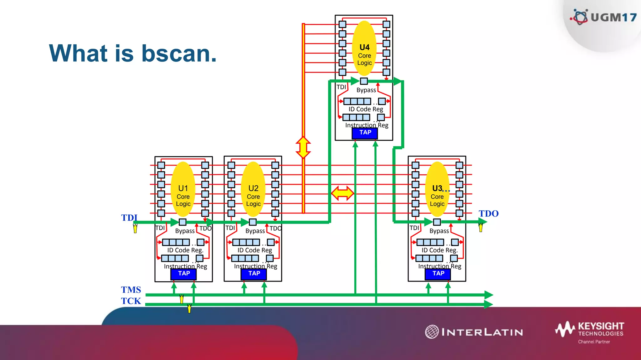
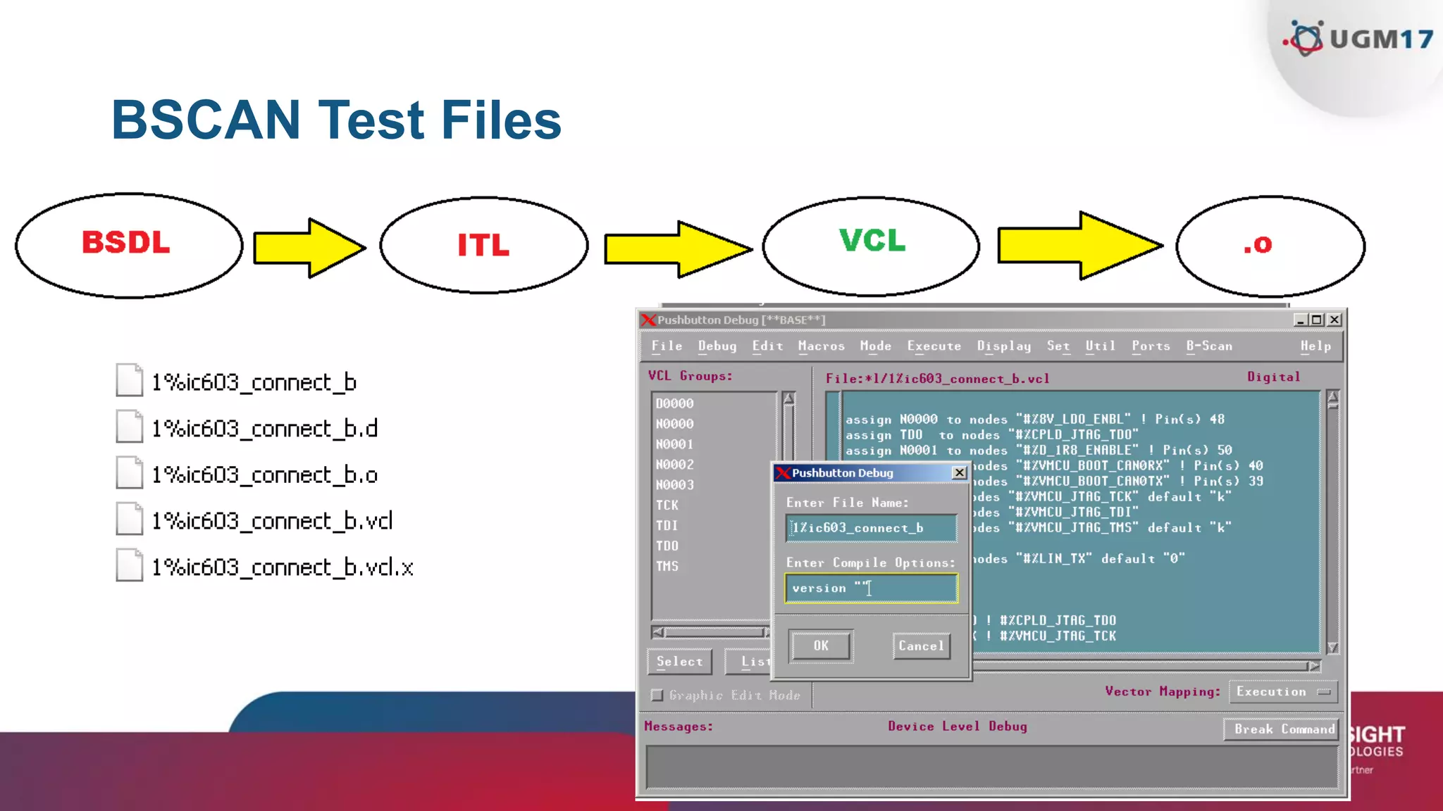
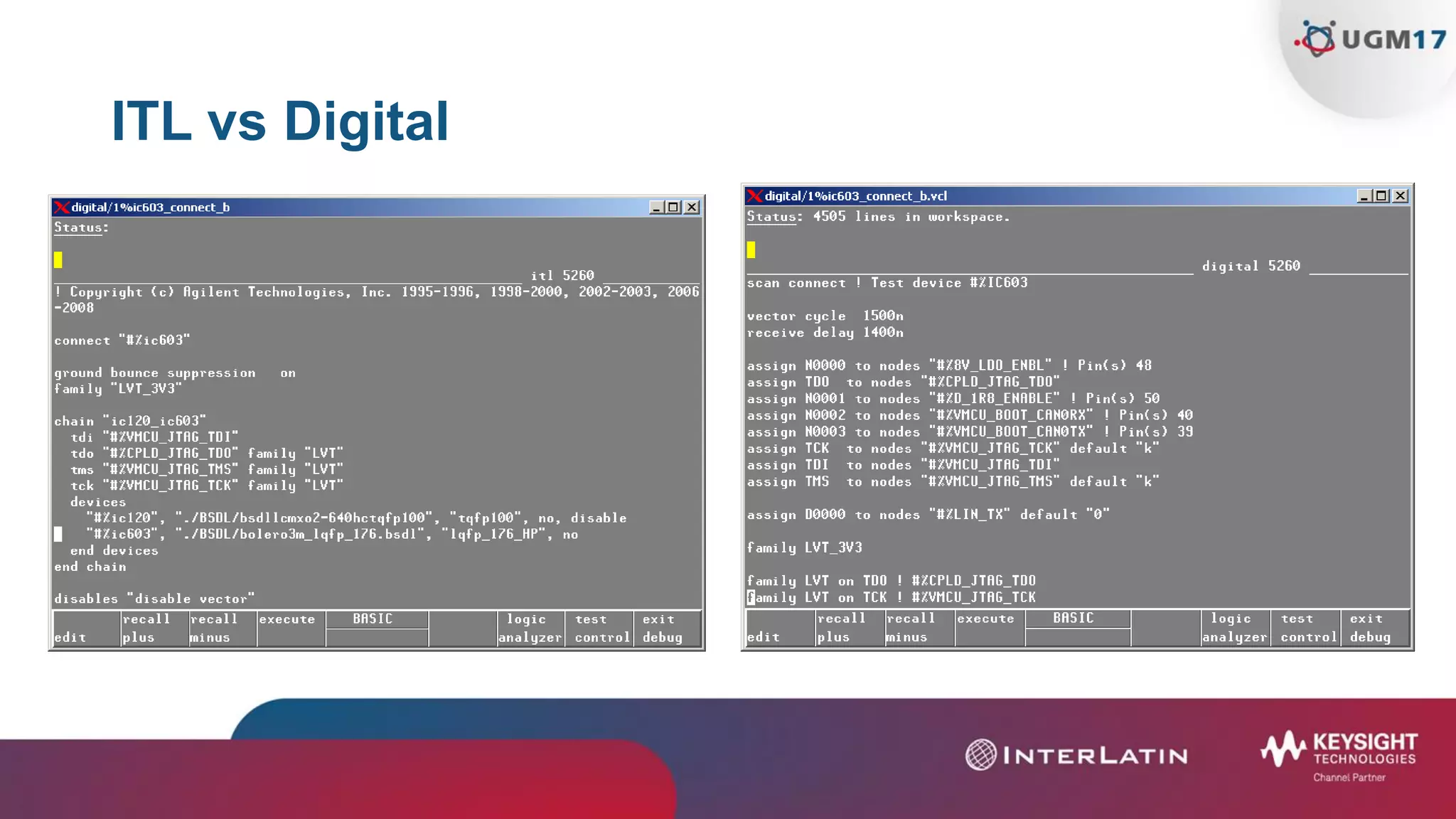
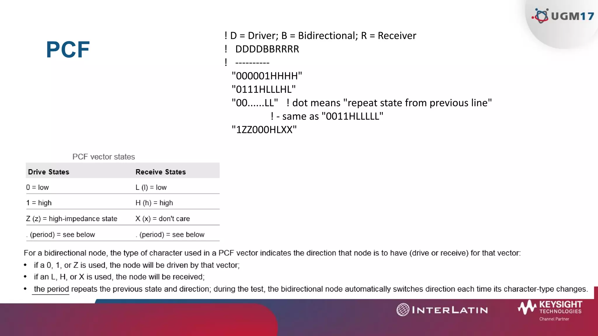
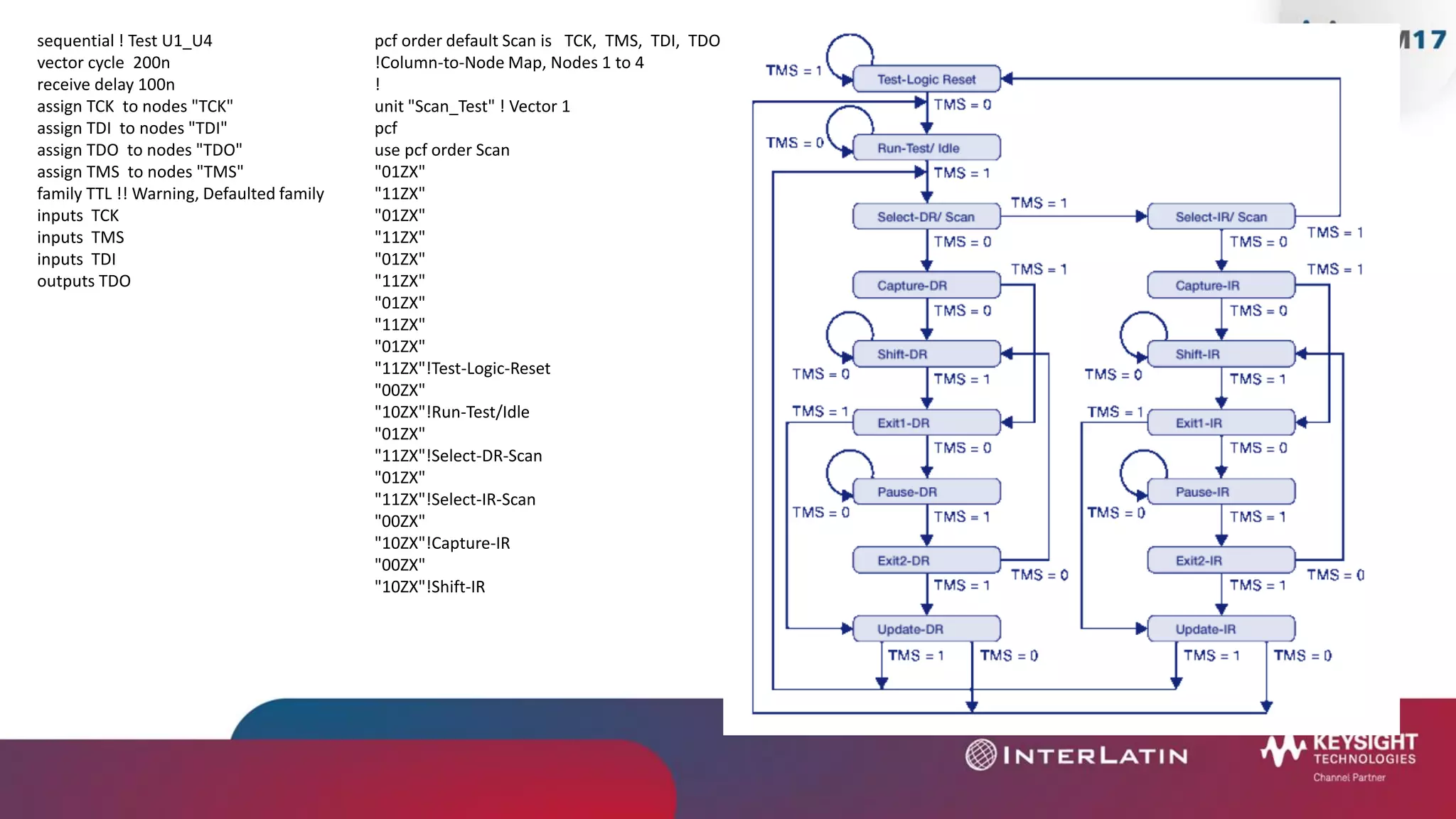
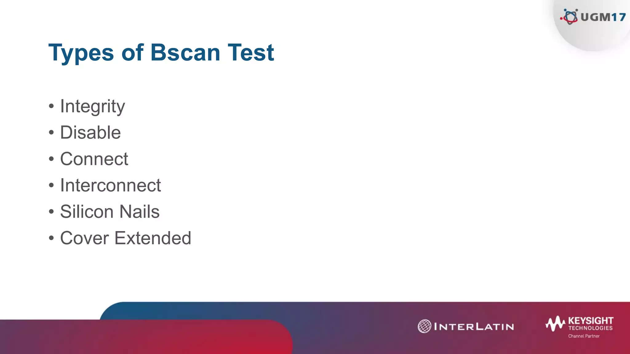
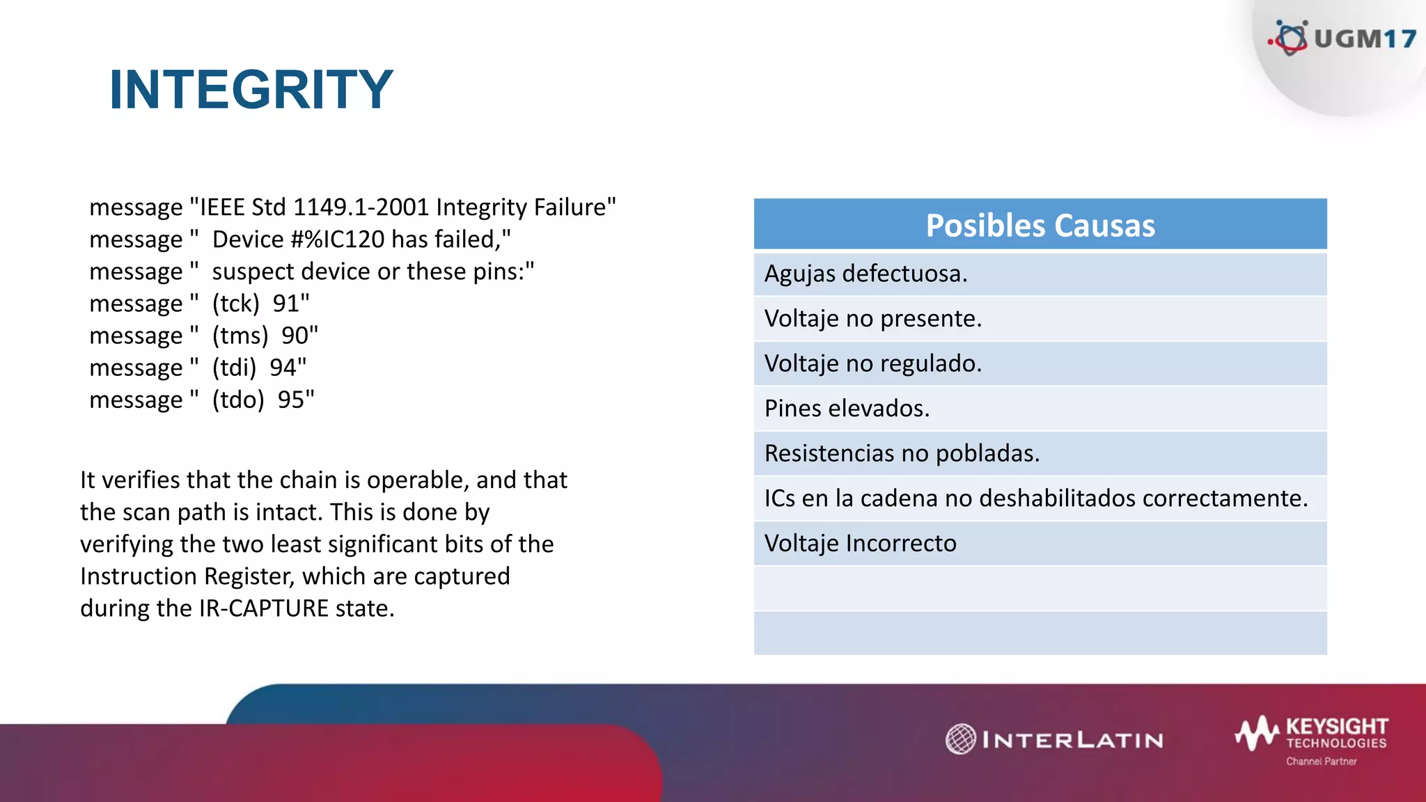
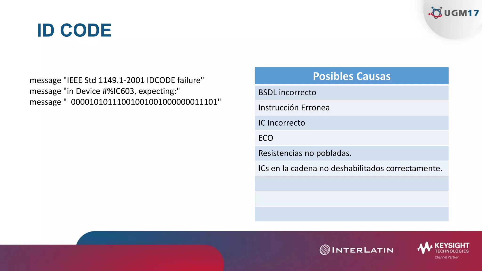
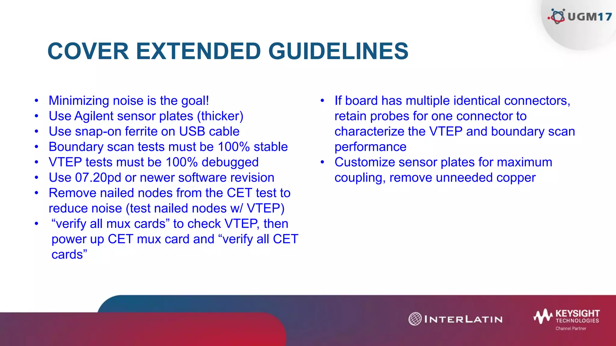
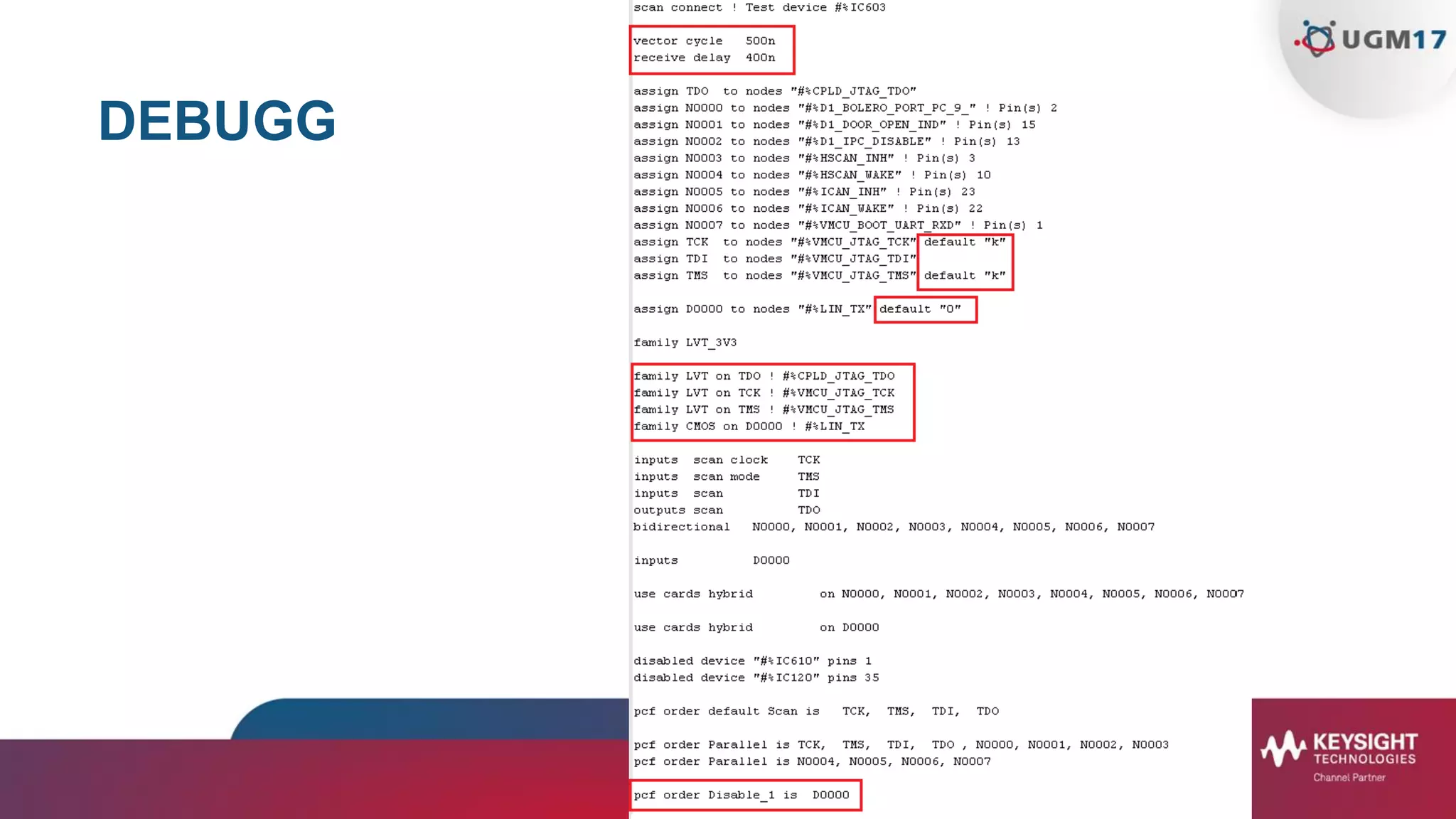
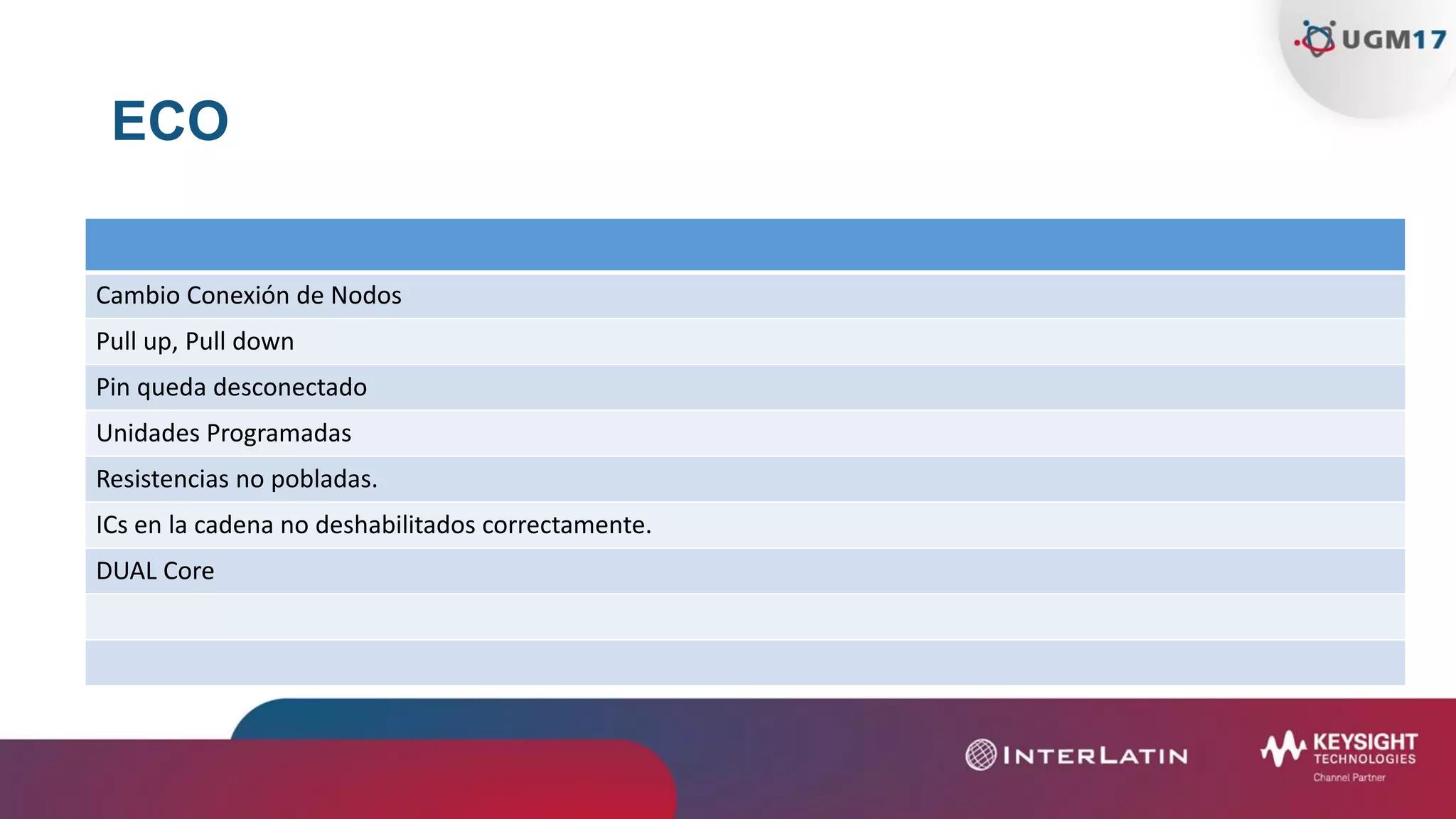
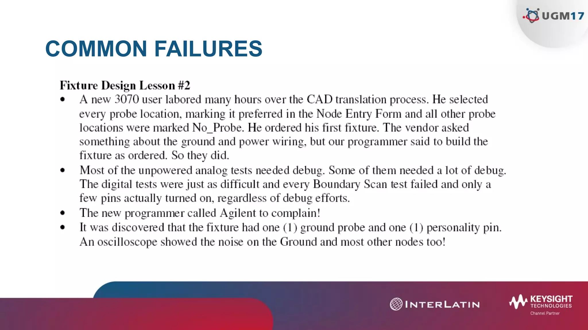
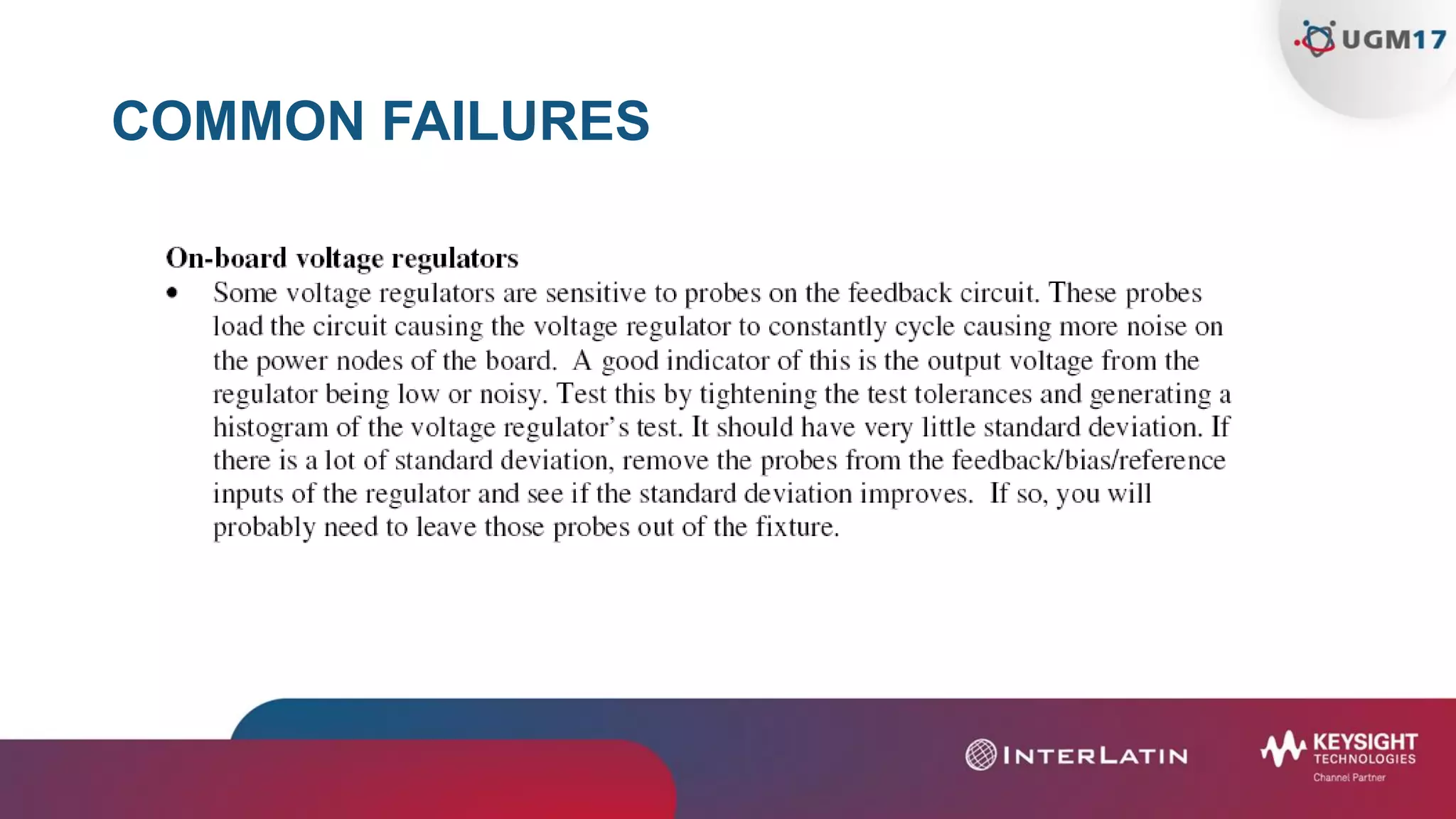
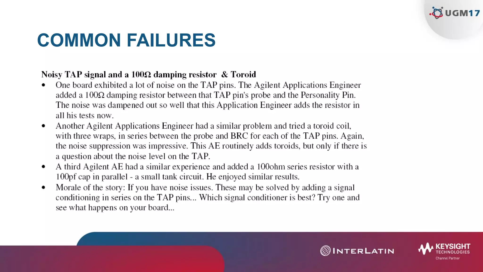


The document provides a comprehensive overview of boundary scan (BSCAN) testing, emphasizing its application in verifying digital integrated circuits per IEEE standard 1149.1. It outlines the types of BSCAN tests, common failures, and troubleshooting tips, including potential causes and error messages for various failure scenarios. Additionally, it includes guidelines for effective BSCAN test execution and considerations for minimizing noise during tests.


![Design for Test [DFT]-1 (1).pdf DESIGN DFT](https://cdn.slidesharecdn.com/ss_thumbnails/designfortestdft-11-231227151941-28a508a3-thumbnail.jpg?width=640&height=640&fit=bounds)