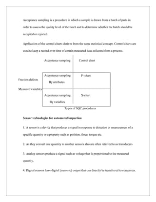
INSTITUTION OF ENGINEERS INDIA
MANUFACTURING
AUTOMATION MC-434
SELF EXPLANATORY NOTES
ZAIN KIRMANI
Notes for Section B examination in mechanical and production engineering of institution of
engineers India. These notes are prepared for the students who are taking exams of IEI.
Various sources (both national and international) has been used while preparing
Manufacturing Automation
MC-434
Syllabus
GROUP A
 Definition of automation, reasons for automating, pros and cons of automation.
 Fundamentals of manufacturing and automation: Manufacturing operations and
automation strategies, production economics.
 High volume production systems: Detroit type automation, analysis of automated flow
lines, assembly and line balancing, automated assembly systems.
 Numerical control production systems: CNC, DNC and adaptive control.
GROUP B
 Industrial robots: Robotics technology, robot applications.
 Material handling and storage: Automated materials handling, automated storage and
retrieval systems.
 Flexible manufacturing systems (FMS): FMS workstations, material handling and
storage systems, computer control systems, planning the FMS, analysis methods for
FMS, applications and benefits.
 Automated inspection and testing: Inspection and testing, statistical quality control,
automated inspection principles and methods, sensor technologies for automated
inspection, coordinate measuring machines, other contact inspection methods, machine
vision and other optical inspection methods, and non-contact inspection methods
MANUFACTURING AUTOMATION MC-434
Group A
Definition of Automation: Automation is a technology concerned with the operation of
Mechanical Electronics and Computer based systems to operate and control production.
This technology includes
 Automatic machine tools to process parts.
 Automatic assembly machines.
 Industrial robots.
 Automatic material handling and storage systems (ASRS).
 Automatic inspection system and quality control.
 Feedback control and computer process control.
 Computer system for planning data collection and decision making to support
manufacturing activities.
Automation begins where mass production leaves off
Reasons for automating
 Reduction or total elimination of tedious and routine operation.
 Creation of new and more interesting jobs.
 Increase in the productive capacity of industry.
 Greater flexibility through the use of standard production units.
 Higher standard of living.
Types of automation
1. Fixed automation:
 The sequence of processing (or assembly) operations is fixed by the equipment
configuration.
 High initial investment for custom engineered equipments.
 High production rate.
 Relatively inflexible in accommodating product changes
 Example: Mechanised assembly line (1913), Machining transfer lines (1924).
2. Programmable automation
 The production equipment is designed with the capability to change the sequence of
operations to accommodate different product configurations.
 High investment in general purpose equipment.
 Low production rate with respect to fixed automation.
 Flexibility to deal with the change in the product configuration.
 Example: NC machine tool (1952) and industrial robots (1961).
3. Flexible automation
 Extension of programmable automation. It is a system capable of producing a variety
of products with virtually no time loss for changeovers from one product to the next.
 High investment for a custom engineered system.
 Continuous production of variable mixtures of products flexibility.
 Example: Flexible manufacturing system (FMS)
Pros and Cons of automation
Pros Cons
1. It eliminates human error.
2. It eliminate the need to hire new
administrative employees at significant cost
saving.
3. Process automation lends itself to
removing the most boring busy work tasks.
This frees up your workforce to tackle task
that humans do better than computer
1. Requires technical acumen or familiarity
at least to implement.
2. Require change in management.
3. Each new automation requires a quality
assurance (QA) process which takes varying
degree of effort and time.
Fundamentals of manufacturing and automation
Manufacturing operations: There are certain basic activities that must be carried out in a
factory to convert raw materials into finished products. Limiting our scope to a plant engaged
in making discrete products, the factory activities are
1. Processing and assembly operations.
2. Material handling.
Manufacturing
processes
3. Inspection and test.
4. Coordination and control.
Manufacturing operations can be classified into
1. Processing operations.
2. Assembly operations.
Fig: flow chart of manufacturing processes
Surface enhancing
Processing
operation
Property enhancing
Shaping process
Mechanical
fastening
Assembly
operation
Permanent joining
Processing operations:
1. A processing operations transform a work material from one state of completion to a
more advanced state that is closer to the final desired part or product.
2. It adds value by changing the geometry properties or appearance of the starting
material.
3. A processing operation uses energy to alter a work parts shape, physical properties or
appearance to add value to the material.
4. The forms of energy include mechanical, thermal, electrical and chemical.
5. Three categories of processing operation are
i) Shaping operations.
ii) Property enhancing operations.
iii) Surface processing operations.
Assembly operations
1. The second basic type of manufacturing operation is assembly in which two or more
separate parts are joined to form a new entity.
2. Components of the new entity are connected together either permanently or semi
permanently.
3. Permanent joining includes welding, brazing, soldering and adhesive bonding.
Material Handling
Materials handling is the art and science involving the moving, packaging and storing of
material in any form.
The essential requirements of a good material handling system are
1. Efficient and safe movements of a good materials handling system.
2. Timely movement of the materials when needed.
3. Supply of materials at the desired rate.
Inspection and test
Inspection and test quality control activities. The purpose of inspection is to determine
whether the manufactured product meets the established design standards and
specifications. Testing is generally concerned with the functional specifications of the
final product rather than with the individual parts that go into the product.
Coordination and Control
Coordination and controlling in manufacturing includes both the regulation of individual
processing and assembly operations as well as the management of plant level activities.
Control at the plant level includes effective use of labour, maintenance of the equipments,
moving materials in the factory, controlling inventory, shipping products of good quality
on schedule and keep plant operating cost at minimum level.
Automation strategies
USA principle: The USA principle is a common sense approach for automation projects.
Similar procedures have been suggested in the manufacturing and automation trade
literature but none has a more captivating title than this one.
USA stands for
U- Understanding the existing process.
S- Simplify the process.
A-Automate the process.
If automation seems a feasible solution to improving productivity, quality or other
measures of performance than 10 strategies are provide.
1. Specialization of operations: The first strategy involves the use of special purpose
equipment designed to perform one operation with the greatest possible efficiency.
This is analogous to the concept of labour specialization which is employed to
improve labour productivity.
2. Combined operations: Production occurs as a sequence of operations complex parts
may require dozens or even hundreds of processing steps. This will accomplished by
performing more than one operation at a given machines thereby reducing the number
of separate machines needed .Manufacturing lead time is reduced for better customer
service.
3. Simultaneous operations: A logical extension of the combined operations strategy is
to simultaneously perform the operations that are combined at one work station. In
effect two or more processing (or assembly) operations are being performed
simultaneously on the same work part thus reducing total processing time.
4. Integration of operation: another strategy is to link several workstations together
into a single integrated mechanism using automated work handling devices to transfer
parts between stations. In effect this reduces the number of separate machines through
which the product must be scheduled. With more than one work station several parts
can be processed simultaneously thereby increasing the overall output of the system.
5. Increased flexibility: This strategy attempts to achieve maximum utilization of
equipment for job shop and medium volume situation by using the same equipment
for a variety of parts or products. It involves the use of flexible automation concepts.
Prime objectives are to reduce set up time and programming time for the production
machine. This normally translates into lower manufacturing lead time and less work
in process.
6. Improved material handling and storage: A great opportunity for reducing non
productive time exist in the use of automated material handling and storage systems.
7. On line inspection: Inspection for quality of work is traditionally performed after the
process is completed. This means that any poor quality product has already been
produced by the time it is inspected. Incorporating inspection into the manufacturing
process as the product is being made. This reduces scrap and brings the overall
quality of product closer to the nominal specifications intended by the designers.
8. Process control and optimization: This includes a wide range of control schemes
intended to operate the individual process and associated equipment more efficiently.
By this strategy the individual process times can be reduces and product quality
improved.
9. Plant operations control: This strategy is concerned with control at the plant level. It
attempts to manage and coordinate the aggregate operations in the plant more
efficiently. Its implementation usually involves a high level computer networking
within the factory.
10. Computer integrated manufacturing (CIM): Taking the plant operations control
one level higher we have the integration of factory operations with engineering design
and the business functions of the firm. CIM involves
1. Computer applications.
2. Computer data bases.
3. Computer networking through the enterprise.
Production economics
Production is a process of combining various material inputs (plan know how) in order to
make something for consumption (output). It is the act of creating output a good or service
which has value and contributes to the utility of individuals. Economic well being created
in a production process meaning all economic activities that aim directly or indirectly to
satisfy human wants and needs. The degree to which the needs are satisfied is often
accepted as a measure of economic well being.
High volume production system
Detroit type automation
Analysis of automated flow lines: An automated flow lines consists of several machines
or workstations which are linked together by work handling devices that transfer parts
between the stations. The transfer of work parts occurs automatically and the workstations
carry out their specialized functions automatically.
Objectives of use of flow line automation
1. To reduce labour cost.
2. To increase production rates.
3. To reduce work in process.
4. To minimize distance moved between operations.
5. To achieve specialization of operations
6. To achieve integration of operations.
Configuration of automated flow lines
1. In line type: This consists of a sequence of work stations in a more or less straight line
arrangement.
In line configuration
2. Segmented in line type: It consists of two or more straight line which are usually
perpendicular to each other with L, U or rectangular shaped. The flow of work can
take a few 90° turns either for work piece reorientation factory layout limitations or
other reasons and still qualify as a straight line configuration.
3. Rotary type: In this type the work parts are indexed around a circular table or dial. The
workstations are stationary and usually located around the outside periphery of the
dial. The parts ride on the rotating table and are registered or positioned in turn at each
station for its processing or assembly operation.
Rotary configuration
Assembly and line balancing-
1. A manual assembly line is a production line that consists of a sequence of workstations
where assembly tasks are performed by human workers.
2. Products are assembled as they move along the line.
3. At each station a portion of the work is performed on each unit.
4. The common practice is to launch base parts onto the beginning of the line at regular
intervals.
Line balancing- There are various methods of line balancing typically known as line
balancing algorithm they are
1. Largest candidate rule.
2. Kilbridge and wester method.
3. Ranked positioned weight method.
4. Computerized techniques.
Largest candidate rule: This rule consists of the following
1. List all the work elements in descending order based on their Tek values.
2. Start at the top of the list and selecting the first element that satisfies precedence
requirements and does not cause the total sum of Tek to exceed the allowable Ts value.
3. When an element is assigned start back at top of the list and repeat selection process.
4. When no more elements can be assigned to the current station proceed to next station.
5. Repeat steps 1 and 2 until all the elements have been assigned to as many stations as
needed.
Kilbridge and wester method-
1. In the kilbridge and wester method the work elements in the precedence diagram are
arranged in column.
2. The elements can than be organized into a list according to their columns with the
elements in the first column listed first.
Work elements in kilbridge and wester method
Ranked positioned weights method-
1. In this method a ranked positioned weight value (called RPW) is computed for each
element.
2. The RPW takes into account both Tek value and its position in the precedence diagram.
3. Specifically RPW is calculated by summing Tek and all other times for elements that
follow Tek in the arrow chain of the precedence diagram.
Computerized techniques-
1. The all three methods described earlier have all been developed into computer programs
to solve large line balancing problems in industry.
2. There are two methods using computer techniques. viz COMSOAL and CALB.
COMSOAL
1. The acronym stands for computer method of sequencing operations for assembly lines.
2. COMSOAL is the random generated of a feasible sequence.
3. Such a sequence may be constructed by assigning a positive probability of selection to
each task that will fit in the current time and than selecting one of the task at random.
4. The procedure is repeated until all the tasks have been assigned.
CALB
1. It stands for computer aided line balancing. CALB can be used for both single model
and mixed model lines.
2. For single model line the data required to use the package are the kind of work element
and other constraints.
3. For mixed model lines additional data include production requirements per shift for
each model to be run on the line.
Automated assembly system
The use of mechanized and automated devices to perform the various assembly tasks in an
assembly line or cell.
Fixed automation usually most automated assembly systems are designed to perform a
fixed sequence of assembly steps on a specific product that is produced in very large
quantities.
Application characteristics
1. High product demand.
2. Stable product design.
3. The assembly consists of no more than a limited number of components.
4. The product is designed for automated assembly.
System configuration
1. In-line assembly machine.
2. Dial indexing machine.
3. Carousel assembly system
4. Single station assembly cell.
Multi station VS single station
Multi station assembly machine or line.
1. Faster cycle rate.
2. High production rate.
3. More operation per assembly.
4. More components per assembly.
Single station machine or line cell
1. Suited to robotic assembly.
2. Intended for lower production quantities.
Parts delivery at workstations.
1. Hopper- Container for parts.
2. Parts feeder-Removes parts from hopper.
3. Selector/orientor- To assure part is in proper orientation for assembly at work head.
4. Feed track-Moves parts to assembly work head.
5. Escapement and placement device-Removes parts from feed track and places them at
station.
Numerical control production systems: CNC, DNC and
Adaptive control
Device
1.Device punch
2.Floppy disk
3.Cassette recorder
4.Computer terminal
5.Operator
Medium
1.Paper touch
2.Floppy disk
3.Magnetic cassette
4.Hard disk of main frame
5.MCU memory
Steps in NC manufacturing
1. Process planning: It is concerned with deciding. What are the manufacturing
operations needed to be done on the work piece? What would be the sequence of the
operations? What are the conventional and numerical control machines required? What
are the requirements of tooling and work holding?
2. Part programming. (A) To implement the process plan part programming is required
for operations on relevant NC machines, instructions in the form of NC blocks are
written.(B) Part programming is done by keeping in view the part drawing, operation
plan, set up sheets, limitations due to NC machines parameters and NC tooling.
3. Coding of part program on suitable media: The machine language part program has to
be put on suitable medium as per ISO/EIA code so that it can be decoded or
interpreted by the MCU.
Some of the devices are
4. Program or tape proving: The accuracy of the tape or the program is generally tested
and modified by dry runs on the NC machines or by plotting tool paths on the plotters
interfaced with NC machine on the shop floor itself.
5. NC machine operation: The medium containing the program e.g. punched tape the
program listing NC part drawing setup sheets and work blank are now provided to the
NC machine operator.
CNC- Computer Numerical Control
1. A CNC system consisting of the NC controller by dedicated programs (i.e.
software).
2. Thus an X slide control circuit would be replaced by an X slide control program
stored in the read only memory (ROM) of the CNC controller.
3. Similarly many of the NC control functions like interpolation, feed rate control,
deceleration and acceleration etc, can be replaced by control programs in the
ROM.
4. When a stored program has to be executed on the CNC machine the instructions or
blocks in the part program are implemented by the microprocessor with the help of
control programs in ROM.
5. The output from the controller may be either as a sequence of reference pulses or
as a binary word in sampled data system.
TO MACHINE TOOL
Fig: software based CNC
R
A
M
MICRO PROCESSOR
PART PROGRAM 2
PART PROGRAM 1
Input and output
I/O
CONTROL PROGRAM FOR INTERPOLATION
CONTROL PROGRAM FOR X-SLIDE
CONTR CONTROL PROGRAM FOR Z-SLIDE
R
O
M
Direct Numerical Control (DNC)
DNC is the first step towards the factory of future. It is manufacturing system in which a central
computer communicates with the controllers of several machine tools by a direct connection in
real time.
Functions of DNC are
1. To use the memory of the central computer for storing part programs meant for several
NC/CNC machines.
2. To transfer or download directly the part programs from central computer to individual
machine control units of machines.
3. To provide downloading in real time on the shop floor.
4. To establish two way communication.
5. To provide software for processing of the shop floor data for management purpose.
6. To provide for uploading i.e. entry of part programs from CNC systems to the central
computer.
7. To post process part programs which are written in higher language like APT.
8. To provide for integration of the central computer with other systems like those of
CAD/CAM.
9. To provide downloading and uploading between central computer and MCU via a ‘’LINK’’
computer.
Adaptive control
1. Adaptive control implies that the CNC system is responsible to adapt itself to operate at those
machining parameters which results into higher productivity.
2. A party programmer specifies cutting speeds, feed rates, depth of cut etc on the basis of his
knowledge and experience to achieve desired levels of manufacturing objectives say accuracy,
surface finish and productivity.
3.The control situations where in real time the operating parameters i,e cutting speeds, feeds,
depth of cut go on automatically and constantly adjusting themselves so as to .
a) Use the available spindle power to maximum.
b) Limit the deflection of the cutter.
c) Limit the cutting tool temperature.
d) Limit the amplitude of the cutter.
The said control situation can be aptly named as adaptive control with constraints or ACC.
Types of adaptive control.
ACC type of adaptive control:
1. The ACC type adaptive control requires constant measurement of relevant manufacturing
constraints like cutting forces, torques, spindle motor power/current, total wear, tool deflection,
cutting temperature, vibrations etc.
2. Accordingly sensors/transducers/instruments like dynamometers strain gauges accelerometers
and non contact type probes are employed.
3. The measured value is compared by the permissible value which has been in the AC software.
ACO type of adaptive control
1. This type of control measures manufacturing process output variables such as cutting torque,
tool temperature, and tool wear and machine vibrations.
2. These sensors measurements along with programmed feed rate programmed feed rate spindle
speed and constraints are fed into CNC systems and processed by ACO software.
Applications and principles of adaptive control
1. Determining the operating conditions of the process, including measures of performance. This
information is typically obtained by using sensors that measure process parameters such as force,
torque, vibrations and temperature.
2. Configuration the process control in response to the operating conditions may provoke a
decision to make a major switch in control strategy.
3. Continue to monitor the operation making further changes in the controller as needed.
Group B
Industrial robots
An industrial robot has been defined as a programmable multifunctional manipulator design to
move materials, parts, tools, or other devices by means of variable programmed motions and to
perform a variety of other tasks. In a broader context the term robot also includes manipulators
that are activated directly by an operator.
Robot components
1. Manipulator: Also called arm and wrist the manipulator is a mechanical unit that provides
motions (trajectories) similar to those of a human arm and hand using various devices such as
linkages, gears and joints.
2. End effectors: The end of the wrist in a robot is equipped with an end effector also called end
of arm tooling end effectors can be custom made to meet special handling requirements.
Mechanical grippers are the most commonly used end effectors and are equipped with two or
more fingers.
Depending on the type of operation end effectors may be equipped with any of the following
a) Grippers, hooks, scoops, electromagnets, vacuum cups and adhesive fingers for materials.
b) Spray guns for painting.
c) Various attachments such as for spot and arc welding and for arc cutting.
d) Power tools such as drills, nut drivers, burrs and sanding belts.
e) Measuring instruments such as dial indicator and laser or contact probes.
Compliant end effectors: They are used to handle fragile materials or to facilitate assembly.
They can use elastic mechanism to limit the force that can be applied to a work piece or part and
they can be designed with a specific required stiffness.
3. Power supply: Each motion of the manipulator in linear and rotational axes is controlled and
regulated by independent actuators that use an electrical, pneumatic or hydraulic power supply.
4. Control system: Whereas manipulators and end effectors are the robots arms and hands the
control system is the brain of a robot also known as the controller the control system is the
communication and information processing system that gives commands for the movement of
robot it stores data to initiate and terminate movements of the manipulator. The controller acts as
the nerves of the robot it interfaces with the computers and other equipments such as
manufacturing cells or assembly operations.
Classifications of robots
1. Fixed sequence and variable sequence robots: Also called a pick and place robot a fixed
sequence robot is programmed for specific sequence of point to point movements the cycle is
repeated continuously. They are simple and less expensive and can be programmed for multiple
specific operations if the variable sequence robots are used.
2. Playback robots: An operator leads or walks the playback robot and its end effector through
the desired path. The operator teaches the robot by showing it what to do? The robot memorizes
and records the path and sequence of motions.
3. Numerically controlled robots: This is same more or less as a CNC machine. The robot is
servo controlled by digital data and its sequence of movements can be changed with relative
ease. As in CNC machines there are two types of controls point to point, continuous path. Points
to point robots are easy to program and have higher payload whereas continuous path robots
have higher accuracy and have lower payload.
4. Intelligent (sensory) robots: The intelligent robot is capable of performing some of the
functions and tasks carried out by human beings. It is equipped with a variety of sensors with
visual and tactile capabilities powerful computers are required to control this type of robot.
Application of robots
1. Material handling: Such as (a) casting and moulding operations (b) heat treatment operations
for loading and unloading from furnaces (c) forming and shaping operations for the movement of
materials.
2. Spot welding: By robots especially for automobiles and truck bodies produce reliable welds of
high quality.
3. Finishing operations: Such as grinding, deburring and polishing can be done by using
appropriate tools attached to end effectors.
4. Applying adhesives and sealants: Such as in the automobile frame.
5. Spray painting: Particularly of parts with complex shapes and cleaning operations.
6. Automated assembly: Performing very repetitive operations.
7. Inspection and gauging: In various stages of manufacturing at speeds much higher than those
that can be achieved by humans.
Six basic motions or Degrees of freedom
1. Vertical motion: The entire manipulator arm can be moved up and down vertically either by
means of shoulder swivel i.e. turning it about a horizontal axis or by sliding it in a vertical slide.
2. Radial motion: That means in and out movement to the manipulator arm is provided by elbow
extension by extending it and drawing back.
3. Rotational motion: Clockwise or anti clockwise rotation about the vertical axis to the
manipulator arm is provided through arm sweep.
4. Pitch motion: It enables up and down movement of the wrist and involves movement as well.
It is also known as wrist band.
5. Roll motion: Also known as wrist swivel it enables rotation of wrist.
6. Yaw: Also called as wrist yaw it facilitates rightward or leftward swiveling movement of the
wrist.
Basic coordinate systems or configuration
1. Cartesian coordinate system: The robot with this type of configuration has sliding motions
along the three standard orthogonal axes X, Y, Z. The slide moving along th X axis enables a
right and left motion that along Y axis a forward and backward motion and along Z axis an up
and down motion.
2. Polar coordinate system: Also known as spherical coordinate system. A robot designed and
built around this configuration carries two angular (rotary) motions and one radial (linear)
motion. This type of robot carries a rotary motion.
3. Cylindrical coordinate system: In this system the robot carries two linear motions and one
rotary motion. The body of the robot is a vertical column which can rotate about a vertical axis to
provide the rotary motion. This configuration called ‘cylindrical’ because the workspace or the
work envelope within which the arm of this robot can be moved is cylindrical in shape.
4. Revolute coordinate system: Also known as anthromorphic configuration articulated
configuration or jointed arm configuration. It is resemble to human arm comprises number of
straight parts which are connected together by means of different joints. The whole arm is
mounted on the base which can be rotated about a vertical axis.
Material handling and storage
Material handling is defined as the functions and systems associated with the transportation,
storage and control of materials and parts in the manufacturing cycle of a product. During this
cycle raw materials and parts are typically moved from storage to machines, from machine to
machine, from inspection to assembly and to inventory and finally to shipment. Material
handling operations must be repeatable and reliable. Plant layout is important for the orderly
flow of materials and components throughout the manufacturing cycle.
Material handling and storage
 Human handling
 Forklifts trucks. Manual handling
 Cranes and hoists.
 Conveyor systems.
 Automated guided vehicles systems. Automated handling
 Robots.
The last three systems are considered in the domain of automated system as they are highly
mechanized / automated hence they are used in integrated manufacturing system.
Conveyor systems
1. This system is used where materials must be moved in large quantities between specific
locations over a fixed path.
2. Most conveyor systems are powered to move the loads along the pathways.
3. Some conveyors use gravity to cause the load to travel from higher elevation in the system to
lower elevation
Automated guided vehicles (AGVs)
1. AGV is a vehicle equipped with automated guidance equipment either electromagnetic or
optical. Such a vehicle is capable of following prescribed guide path and many be equipped with
vehicle programming.
2. Stop selection blocking and any other special functions required for the system.
3. AGVs are computer controlled hence they are more flexible than traditional material handling
equipments.
Automated storage and retrieval system (AS/RS)
An automated storage and retrieval system (AS/RS) can be defined as a storage system under
which a defined degree of automation is to be implemented to ensure precision accuracy and
speed in performing storage and retrieval operations.
Functions of AS/RS.
1. Removal of an item from a storage location automatically.
2. Transferring the above items to a specific processing or interface point.
3. After receiving an item from a processing or interface point it is automatically stored at a
predetermined location.
Objectives of AS/RS
 Increasing the storage capacity.
 Increasing the stock rotation.
 Utilization of maximum floor space.
 Recovering the space for manufacturing facilities.
 Customer service to be improved.
 Ensuring safety in storage function.
 Increasing the labour productivity.
 Reduce labour cost.
 Reduce pilferage and improving security.
AS/RS components.
1. Storage space: 3-D space in the storage racks used to store a single load unit of material.
2. Storage rack: It comprises storage locations, bays, rows,
3. Bay: Height of storage from floor to ceiling.
4. Row: Series of bays placed side by side.
5. Aisle: Spacing between two rows for the machine operations of AS/RS.
6. Aisle unit: it encompasses aisle space and racks adjacent to an aisle.
7. Storage structure: Rack framework made of fabricated steel that support the loads
contained in AS/RS and used to store inventory items.
Types of AS/RS
1. Unit load AS/RS: It is used to store and retrieve loads that are palletized or stored in
standard sized containers. The system is computer controlled.
2. Mini load AS/RS: It is designed to handle small loads such as individual parts, tools and
supplies that are contained in bins or drawers in the storage system.
3. Deep lane AS/RS: High density unit load storage system that is appropriate for storing
large quantities of stock. The items are stored in multi deep storage with up to m10 times in a
single rack one load behind the next.
4. Automated item retrieval system: It is designed for retrieval of individual items or small
product cartoons. These items are stored in lanes rather than bins or drawers.
5. Man on board AS/RS: This system allows storage of items in less than unit quantities.
Human operator rides on the carriage of the S/R machine to pick up individual items from a
bin or a drawer.
Flexible manufacturing systems (FMS)
Is a manufacturing system in which is some amount of flexibility that allows the system to
react in case of changes whether predicated or unpredicted.
FMS workstations: The processing or assembly equipment used in an FMS depends on the
type of work accomplished by the system. The various types of workstations found in FMS
are:
1. Load/ Unload station
(i) It is the physical interface between the FMS and the rest of the factory.
(ii) Raw work part enters and finished work part exits the system.
(iii) Loading can be done manually or automatically.
(iv) The load/ unload station should be ergonomically designed to permit convenient and safe
movement of work parts.
2. Machining station
(i) The most common applications of FMS are machining operations.
(ii) The work stations used in these systems are therefore predominantly CNC machine tools.
(iii) Most common is CNC machining centre.
(iv) Machining centers can be ordered with automobile pallet changers that can be readily
interfaced with the FMS part handling system.
3. Other processing stations.
(i) The FMS concept has been applied to other processing operations in addition to
machining.
(ii) The processing workstations consists of press working operations such as punching,
shearing and certain bending and forging and forming processes.
(iii) Also FMS are being developed to automate the forging process.
4. Assembly
(i) Some FMS are designed to perform assembly operations.
(ii) Flexible automated assembly systems are being developed to replace manual labour in
the assembly of products typically made in batches.
(iii) Industrial robots are often used as the automated workstations in these flexible assembly
systems.
5. Other stations and equipments
(i) Inspection can be incorporated into an FMS either by including an inspection operation at
a processing work station or by including a station specifically designed for inspection.
Material handling and storage systems
1. The second major component of an FMS is material handling and storage system. A
material handling system can be simply defined as an integrating system involving such
activities as handling, storing and controlling of materials.
2. The primary objectives of using a material handling system is to ensure that the material in
the right amount is safely delivered to the desired destination at the right time and at
minimum cost.
3. The material handling system is properly designed not only to ensure the minimum cost
and compatibility with other manufacturing equipments but also to meet safety concerns.
Automated Material handling and storage systems
The various automated material handling systems are used to transport work parts and
assembly parts between the processing stations. The various functions of automated material
handling are
(i) Random and independent movement of work parts between work stations.
(ii) Handling of a variety of work part configurations.
(iii) Temporary storage.
(iv) Convenient access for loading and unloading of work parts.
(v) Compatible with computer control.
Computer control system
It is used to coordinate the activities of the processing stations and the material handling
systems in FMS. The various functions of computer control system are
(i) Control of each work stations
(ii) Distribution of control instruction to work stations.
(iii) Production control.
(iv) Traffic control.
(v) Shuttle control.
(vi) Work handling system and monitoring.
(vii) System performance monitoring and reporting.
Application characteristics (FMS)
Planning the FMS
1. Part family considerations
(i)A choice has to be made regarding group technology (GT) and the part family to be
produced on FMS.
(ii)The FMS cannot be completely flexible and so cannot handle any part whatsoever there
must be some considerations on the creation of a composite part with all possible physical
attributes of the parts that may be processed in the FMS.
2. Process requirement
(i)Once the entire range of possible parts to be processed are known we must use this
information to help choose associated processing requirements for each part and thus the type
of equipment that should be used to process the parts.
3. Physical characteristics of the work parts: Size and weight of work parts determine size of
the machines required to process the parts. It also determines the size of the material handling
system needed.
4. Production volume: Production quantities must be determined as these tell us how many
machines of each type will be required.
Analysis methods for FMS
1. Deterministic models: Models that are used to gain starting estimations of system
performance but not for complex phenomena such as the buildup of queues and other
dynamics that can impair system performance.
2. Queuing models: These attend to issue of queuing not examined in deterministic models
and they examine various simple system configurations.
3. Discrete event simulation: It is often used in the latter parts of the system design to
determine the most accurate methods for modeling specific attributes of the FMS.
Characteristics handled here include layout configuration number of pallets in the system and
production scheduling rules.
4. Other techniques: This is a hold all title that includes various approaches from
mathematical programming, heuristic approaches and a number of operational research
techniques.
Applications and benefits of FMS.
FMS are typically used for mid volume mid variety production. If the part or product is made
in high qualities with no style variations than a transfer line or similar dedicated production
system is most appropriate.
Advantages of FMS
1. Faster, lower cost changes from one part to another which will improve capital utilization.
2. Lower direct labour cost due to reduction in number of workers.
3. Reduce inventory due to the planning and programming precision.
4. Consistent and better quality due to the automated control.
5. Lower cost/ unit of output due to the greater productivity using the same number of
workers.
Manufacturing
process
Automated inspection
Automated inspection and testing
Automated inspection: It is defined as the automation of one or more steps involved in the
inspection procedure. Automated or semi automated inspection can be implemented in the
number of alternative ways.
(a) Automated presentation of parts by an automatic handling system with manual
examination and decision steps.
(b) Machine with manual loading parts into the machine doing automated examination and
decision making.
(c) Completely automated inspection system in which parts presentation, examination and
decisions are performed.
Error!
work part out
Feedback process control (a)
Work part out
(b) Defects Part sort
Work part in Manufacturing
process
Automated inspection
Study
Action step resulting from automated inspection
(a) Feedback process control.
(b) Sorting of parts into two or more quality levels.
Statistical quality control (SQC)
1. Statistics means data a good amount of data to obtain reliable results.
2. The science of statistics handles this data in order to draw certain conclusions.
3. Statistical techniques find extensive applications in quality control, production planning
and control (PPC) etc.
Steps in SQC
Techniques used in SQC
1. Sampling inspection.
2. Analysis of data.
3. Control charting.
Statistically quality control is generally divided into two categories (i) acceptance sampling
control chart.
Do
Plan
Act
Acceptance sampling Control chart
Fraction defects
Measured variables
Acceptance sampling X-chart
By variables
P- chart
Acceptance sampling
By attributes
Acceptance sampling is a procedure in which a sample is drawn from a batch of parts in
order to assess the quality level of the batch and to determine whether the batch should be
accepted or rejected.
Application of the control charts derives from the same statistical concept. Control charts are
used to keep a record over time of certain measured data collected from a process.
Types of SQC procedures
Sensor technologies for automated inspection
1. A sensor is a device that produces a signal in response to detection or measurement of a
specific quantity or a property such as position, force, torque etc.
2. As they convert one quantity to another sensors also are often referred to as transducers
3. Analog sensors produce a signal such as voltage that is proportional to the measured
quantity.
4. Digital sensors have digital (numeric) output that can directly be transferred to computers.
5. Analog to digital converters (ADCs) are used for interfacing analog sensors with
computers.
Sensors classification
1. Mechanical sensors: Measures quantities such as position, shape, velocity, force and
torque.
2. Electrical sensors: Measures voltage, current, charge etc.
3. Magnetic sensors: Measures magnetic field, flux, permeability.
4. Thermal sensors: Measures temperature, flux, conductivity etc.
5. Acoustic, ultrasonic, chemical, optical, radiation, laser and fiber optic sensors.
Coordinate measuring machines
1. One of the important developments in versatility in contact type inspection has been the
coordinate measuring machines.
2. These are controlled by computers or numerical control systems.
3. When a component is to be inspected for its profile and other features the program or
coordinate data is downloaded from the central computer as in the case in DNC operation.
4. Some prominent makes of CMM are
(i) Digital electronic automobile (DEA).
(ii) Zeiss universal center (UMC).
(iii) Ferranti (Merlin and Micro).
(iv) Renault automation.
(v) Numerex.
Non contact inspection methods (optical)
Non contact inspection of items is an attractive alternative to the types of methods.
Advantages of non-contact inspection methods are
1. It usually eliminates the need to reposition of the work part.
2. Non contact inspection is usually much faster than contact inspection.
3. It eliminates mechanical wear.
4. It reduces potential danger to people.
5. It removes the possibility of damage to the surface of a part.
Optical systems are the dominant type of non contact inspection method. These systems
generally rely on the use of microelectronics technology and computer processing of the
sensing signals. There are varieties of optical sensing techniques used for inspection work
they are
1. Machine vision
2. Scanning laser beam devices.
3. Photogrammetry
Machine Vision.
1. The machine vision system consists of a TV, camera, a digital computer and an interface
between them that functions as a processor.
2. The combination of system hardware and software digitizes the picture and analyzes the
image by comparing it with data stored in memory.
3. The data are often in the form of a limited number of models of the objects which are to be
inspected.
Basic functions of a machine vision system
Scanning laser beam devices
1. The scanning laser beam device relies on the measurement of time rather than light
although a light sensor is required in its operation.
2. A laser is used to project a continuous thin beam of light.
3. A rotating mirror deflects the beam so that it sweeps across the object to be measured.
4. The light sensor is located at the focal point of the lens system to detect the interruption of
the light beam as it is blocked by the object.
Scanning laser beam device
Photogrammetry
1. Photogrammetry is a technique which may gain in usage in inspection work as it is
perfected.
2. The term is related to or borrowed from aerial reconnaissance and geological mapping
applications.
3. A more recent application of the procedure is in aerospace plants to measure large airframe
assembly fixture.
4. Photogrammetry involves the extraction of three dimensional data from a pair of
photographs taken at different angles.
5. The two photographs can be combined much in the way that a stereoscope uses a pair of
photographs to form a 3D image for the viewer.
Non contact inspection methods (non optical)
The three general types of non optical methods are
1. Electrical field techniques.
2. Radiation techniques.
3. Ultrasonic.
1. Electrical field techniques. They are of 3 types
(i) Reluctance: The reluctance transducers are proximity devices that indicates the presence
and distance from the probe of a ferromagnetic substance object must be electromagnetic.
(ii)Capacitance: The measurement is based on the variable capacitance from part/ probe
coupling.
(iii)Inductance systems operate by subjecting the object to an alternating magnetic field by
means of an electromagnetic coil. The result is that small circulating currents (eddy currents)
are generated in the object.
2. Radiation techniques X- ray radiation techniques are employed for purpose of non contact
inspection in the metal working industry. The amount of radiation absorbed by a material can
be used to measure its thickness and other quality characteristics.
3. Ultrasonic: Ultrasonic in inspection work involves the use of very high frequency (above
20,000 Hz) sound waves to indicate quality. A principle application is in non destructive
testing of materials. This technique can be applied to the problems of determining
dimensional features of work parts.
References:
 M.P Groover. Automation production systems and computer integrated
manufacturing.
 P N rao. N K tiwari and T K kundra. Computer aided manufacturing.
 Video and pdf lectures of NPTEL.
 ASME and California institute of technology (U.S.A).
Manufacturing Automation.pdf

Manufacturing Automation.pdf

  • 1.
    INSTITUTION OF ENGINEERSINDIA MANUFACTURING AUTOMATION MC-434 SELF EXPLANATORY NOTES ZAIN KIRMANI Notes for Section B examination in mechanical and production engineering of institution of engineers India. These notes are prepared for the students who are taking exams of IEI. Various sources (both national and international) has been used while preparing
  • 2.
    Manufacturing Automation MC-434 Syllabus GROUP A Definition of automation, reasons for automating, pros and cons of automation.  Fundamentals of manufacturing and automation: Manufacturing operations and automation strategies, production economics.  High volume production systems: Detroit type automation, analysis of automated flow lines, assembly and line balancing, automated assembly systems.  Numerical control production systems: CNC, DNC and adaptive control. GROUP B  Industrial robots: Robotics technology, robot applications.  Material handling and storage: Automated materials handling, automated storage and retrieval systems.  Flexible manufacturing systems (FMS): FMS workstations, material handling and storage systems, computer control systems, planning the FMS, analysis methods for FMS, applications and benefits.  Automated inspection and testing: Inspection and testing, statistical quality control, automated inspection principles and methods, sensor technologies for automated inspection, coordinate measuring machines, other contact inspection methods, machine vision and other optical inspection methods, and non-contact inspection methods
  • 3.
    MANUFACTURING AUTOMATION MC-434 GroupA Definition of Automation: Automation is a technology concerned with the operation of Mechanical Electronics and Computer based systems to operate and control production. This technology includes  Automatic machine tools to process parts.  Automatic assembly machines.  Industrial robots.  Automatic material handling and storage systems (ASRS).  Automatic inspection system and quality control.  Feedback control and computer process control.  Computer system for planning data collection and decision making to support manufacturing activities. Automation begins where mass production leaves off Reasons for automating  Reduction or total elimination of tedious and routine operation.  Creation of new and more interesting jobs.  Increase in the productive capacity of industry.  Greater flexibility through the use of standard production units.  Higher standard of living.
  • 4.
    Types of automation 1.Fixed automation:  The sequence of processing (or assembly) operations is fixed by the equipment configuration.  High initial investment for custom engineered equipments.  High production rate.  Relatively inflexible in accommodating product changes  Example: Mechanised assembly line (1913), Machining transfer lines (1924). 2. Programmable automation  The production equipment is designed with the capability to change the sequence of operations to accommodate different product configurations.  High investment in general purpose equipment.  Low production rate with respect to fixed automation.  Flexibility to deal with the change in the product configuration.  Example: NC machine tool (1952) and industrial robots (1961). 3. Flexible automation  Extension of programmable automation. It is a system capable of producing a variety of products with virtually no time loss for changeovers from one product to the next.  High investment for a custom engineered system.  Continuous production of variable mixtures of products flexibility.  Example: Flexible manufacturing system (FMS)
  • 5.
    Pros and Consof automation Pros Cons 1. It eliminates human error. 2. It eliminate the need to hire new administrative employees at significant cost saving. 3. Process automation lends itself to removing the most boring busy work tasks. This frees up your workforce to tackle task that humans do better than computer 1. Requires technical acumen or familiarity at least to implement. 2. Require change in management. 3. Each new automation requires a quality assurance (QA) process which takes varying degree of effort and time. Fundamentals of manufacturing and automation Manufacturing operations: There are certain basic activities that must be carried out in a factory to convert raw materials into finished products. Limiting our scope to a plant engaged in making discrete products, the factory activities are 1. Processing and assembly operations. 2. Material handling.
  • 6.
    Manufacturing processes 3. Inspection andtest. 4. Coordination and control. Manufacturing operations can be classified into 1. Processing operations. 2. Assembly operations. Fig: flow chart of manufacturing processes Surface enhancing Processing operation Property enhancing Shaping process Mechanical fastening Assembly operation Permanent joining
  • 7.
    Processing operations: 1. Aprocessing operations transform a work material from one state of completion to a more advanced state that is closer to the final desired part or product. 2. It adds value by changing the geometry properties or appearance of the starting material. 3. A processing operation uses energy to alter a work parts shape, physical properties or appearance to add value to the material. 4. The forms of energy include mechanical, thermal, electrical and chemical. 5. Three categories of processing operation are i) Shaping operations. ii) Property enhancing operations. iii) Surface processing operations. Assembly operations 1. The second basic type of manufacturing operation is assembly in which two or more separate parts are joined to form a new entity. 2. Components of the new entity are connected together either permanently or semi permanently. 3. Permanent joining includes welding, brazing, soldering and adhesive bonding. Material Handling Materials handling is the art and science involving the moving, packaging and storing of material in any form. The essential requirements of a good material handling system are 1. Efficient and safe movements of a good materials handling system.
  • 8.
    2. Timely movementof the materials when needed. 3. Supply of materials at the desired rate. Inspection and test Inspection and test quality control activities. The purpose of inspection is to determine whether the manufactured product meets the established design standards and specifications. Testing is generally concerned with the functional specifications of the final product rather than with the individual parts that go into the product. Coordination and Control Coordination and controlling in manufacturing includes both the regulation of individual processing and assembly operations as well as the management of plant level activities. Control at the plant level includes effective use of labour, maintenance of the equipments, moving materials in the factory, controlling inventory, shipping products of good quality on schedule and keep plant operating cost at minimum level. Automation strategies USA principle: The USA principle is a common sense approach for automation projects. Similar procedures have been suggested in the manufacturing and automation trade literature but none has a more captivating title than this one. USA stands for U- Understanding the existing process. S- Simplify the process. A-Automate the process.
  • 9.
    If automation seemsa feasible solution to improving productivity, quality or other measures of performance than 10 strategies are provide. 1. Specialization of operations: The first strategy involves the use of special purpose equipment designed to perform one operation with the greatest possible efficiency. This is analogous to the concept of labour specialization which is employed to improve labour productivity. 2. Combined operations: Production occurs as a sequence of operations complex parts may require dozens or even hundreds of processing steps. This will accomplished by performing more than one operation at a given machines thereby reducing the number of separate machines needed .Manufacturing lead time is reduced for better customer service. 3. Simultaneous operations: A logical extension of the combined operations strategy is to simultaneously perform the operations that are combined at one work station. In effect two or more processing (or assembly) operations are being performed simultaneously on the same work part thus reducing total processing time. 4. Integration of operation: another strategy is to link several workstations together into a single integrated mechanism using automated work handling devices to transfer parts between stations. In effect this reduces the number of separate machines through which the product must be scheduled. With more than one work station several parts can be processed simultaneously thereby increasing the overall output of the system.
  • 10.
    5. Increased flexibility:This strategy attempts to achieve maximum utilization of equipment for job shop and medium volume situation by using the same equipment for a variety of parts or products. It involves the use of flexible automation concepts. Prime objectives are to reduce set up time and programming time for the production machine. This normally translates into lower manufacturing lead time and less work in process. 6. Improved material handling and storage: A great opportunity for reducing non productive time exist in the use of automated material handling and storage systems. 7. On line inspection: Inspection for quality of work is traditionally performed after the process is completed. This means that any poor quality product has already been produced by the time it is inspected. Incorporating inspection into the manufacturing process as the product is being made. This reduces scrap and brings the overall quality of product closer to the nominal specifications intended by the designers. 8. Process control and optimization: This includes a wide range of control schemes intended to operate the individual process and associated equipment more efficiently. By this strategy the individual process times can be reduces and product quality improved. 9. Plant operations control: This strategy is concerned with control at the plant level. It attempts to manage and coordinate the aggregate operations in the plant more efficiently. Its implementation usually involves a high level computer networking within the factory.
  • 11.
    10. Computer integratedmanufacturing (CIM): Taking the plant operations control one level higher we have the integration of factory operations with engineering design and the business functions of the firm. CIM involves 1. Computer applications. 2. Computer data bases. 3. Computer networking through the enterprise. Production economics Production is a process of combining various material inputs (plan know how) in order to make something for consumption (output). It is the act of creating output a good or service which has value and contributes to the utility of individuals. Economic well being created in a production process meaning all economic activities that aim directly or indirectly to satisfy human wants and needs. The degree to which the needs are satisfied is often accepted as a measure of economic well being. High volume production system Detroit type automation Analysis of automated flow lines: An automated flow lines consists of several machines or workstations which are linked together by work handling devices that transfer parts between the stations. The transfer of work parts occurs automatically and the workstations carry out their specialized functions automatically. Objectives of use of flow line automation
  • 12.
    1. To reducelabour cost. 2. To increase production rates. 3. To reduce work in process. 4. To minimize distance moved between operations. 5. To achieve specialization of operations 6. To achieve integration of operations. Configuration of automated flow lines 1. In line type: This consists of a sequence of work stations in a more or less straight line arrangement. In line configuration 2. Segmented in line type: It consists of two or more straight line which are usually perpendicular to each other with L, U or rectangular shaped. The flow of work can
  • 13.
    take a few90° turns either for work piece reorientation factory layout limitations or other reasons and still qualify as a straight line configuration. 3. Rotary type: In this type the work parts are indexed around a circular table or dial. The workstations are stationary and usually located around the outside periphery of the dial. The parts ride on the rotating table and are registered or positioned in turn at each station for its processing or assembly operation. Rotary configuration
  • 14.
    Assembly and linebalancing- 1. A manual assembly line is a production line that consists of a sequence of workstations where assembly tasks are performed by human workers. 2. Products are assembled as they move along the line. 3. At each station a portion of the work is performed on each unit. 4. The common practice is to launch base parts onto the beginning of the line at regular intervals. Line balancing- There are various methods of line balancing typically known as line balancing algorithm they are 1. Largest candidate rule. 2. Kilbridge and wester method. 3. Ranked positioned weight method. 4. Computerized techniques. Largest candidate rule: This rule consists of the following 1. List all the work elements in descending order based on their Tek values. 2. Start at the top of the list and selecting the first element that satisfies precedence requirements and does not cause the total sum of Tek to exceed the allowable Ts value. 3. When an element is assigned start back at top of the list and repeat selection process.
  • 15.
    4. When nomore elements can be assigned to the current station proceed to next station. 5. Repeat steps 1 and 2 until all the elements have been assigned to as many stations as needed. Kilbridge and wester method- 1. In the kilbridge and wester method the work elements in the precedence diagram are arranged in column. 2. The elements can than be organized into a list according to their columns with the elements in the first column listed first. Work elements in kilbridge and wester method Ranked positioned weights method- 1. In this method a ranked positioned weight value (called RPW) is computed for each element. 2. The RPW takes into account both Tek value and its position in the precedence diagram.
  • 16.
    3. Specifically RPWis calculated by summing Tek and all other times for elements that follow Tek in the arrow chain of the precedence diagram. Computerized techniques- 1. The all three methods described earlier have all been developed into computer programs to solve large line balancing problems in industry. 2. There are two methods using computer techniques. viz COMSOAL and CALB. COMSOAL 1. The acronym stands for computer method of sequencing operations for assembly lines. 2. COMSOAL is the random generated of a feasible sequence. 3. Such a sequence may be constructed by assigning a positive probability of selection to each task that will fit in the current time and than selecting one of the task at random. 4. The procedure is repeated until all the tasks have been assigned. CALB 1. It stands for computer aided line balancing. CALB can be used for both single model and mixed model lines. 2. For single model line the data required to use the package are the kind of work element and other constraints. 3. For mixed model lines additional data include production requirements per shift for each model to be run on the line.
  • 17.
    Automated assembly system Theuse of mechanized and automated devices to perform the various assembly tasks in an assembly line or cell. Fixed automation usually most automated assembly systems are designed to perform a fixed sequence of assembly steps on a specific product that is produced in very large quantities. Application characteristics 1. High product demand. 2. Stable product design. 3. The assembly consists of no more than a limited number of components. 4. The product is designed for automated assembly. System configuration 1. In-line assembly machine. 2. Dial indexing machine. 3. Carousel assembly system 4. Single station assembly cell. Multi station VS single station Multi station assembly machine or line.
  • 18.
    1. Faster cyclerate. 2. High production rate. 3. More operation per assembly. 4. More components per assembly. Single station machine or line cell 1. Suited to robotic assembly. 2. Intended for lower production quantities. Parts delivery at workstations. 1. Hopper- Container for parts. 2. Parts feeder-Removes parts from hopper. 3. Selector/orientor- To assure part is in proper orientation for assembly at work head. 4. Feed track-Moves parts to assembly work head. 5. Escapement and placement device-Removes parts from feed track and places them at station. Numerical control production systems: CNC, DNC and Adaptive control
  • 19.
    Device 1.Device punch 2.Floppy disk 3.Cassetterecorder 4.Computer terminal 5.Operator Medium 1.Paper touch 2.Floppy disk 3.Magnetic cassette 4.Hard disk of main frame 5.MCU memory Steps in NC manufacturing 1. Process planning: It is concerned with deciding. What are the manufacturing operations needed to be done on the work piece? What would be the sequence of the operations? What are the conventional and numerical control machines required? What are the requirements of tooling and work holding? 2. Part programming. (A) To implement the process plan part programming is required for operations on relevant NC machines, instructions in the form of NC blocks are written.(B) Part programming is done by keeping in view the part drawing, operation plan, set up sheets, limitations due to NC machines parameters and NC tooling. 3. Coding of part program on suitable media: The machine language part program has to be put on suitable medium as per ISO/EIA code so that it can be decoded or interpreted by the MCU. Some of the devices are
  • 20.
    4. Program ortape proving: The accuracy of the tape or the program is generally tested and modified by dry runs on the NC machines or by plotting tool paths on the plotters interfaced with NC machine on the shop floor itself. 5. NC machine operation: The medium containing the program e.g. punched tape the program listing NC part drawing setup sheets and work blank are now provided to the NC machine operator. CNC- Computer Numerical Control 1. A CNC system consisting of the NC controller by dedicated programs (i.e. software). 2. Thus an X slide control circuit would be replaced by an X slide control program stored in the read only memory (ROM) of the CNC controller. 3. Similarly many of the NC control functions like interpolation, feed rate control, deceleration and acceleration etc, can be replaced by control programs in the ROM. 4. When a stored program has to be executed on the CNC machine the instructions or blocks in the part program are implemented by the microprocessor with the help of control programs in ROM. 5. The output from the controller may be either as a sequence of reference pulses or as a binary word in sampled data system.
  • 21.
    TO MACHINE TOOL Fig:software based CNC R A M MICRO PROCESSOR PART PROGRAM 2 PART PROGRAM 1 Input and output I/O CONTROL PROGRAM FOR INTERPOLATION CONTROL PROGRAM FOR X-SLIDE CONTR CONTROL PROGRAM FOR Z-SLIDE R O M
  • 22.
    Direct Numerical Control(DNC) DNC is the first step towards the factory of future. It is manufacturing system in which a central computer communicates with the controllers of several machine tools by a direct connection in real time. Functions of DNC are 1. To use the memory of the central computer for storing part programs meant for several NC/CNC machines. 2. To transfer or download directly the part programs from central computer to individual machine control units of machines. 3. To provide downloading in real time on the shop floor. 4. To establish two way communication. 5. To provide software for processing of the shop floor data for management purpose. 6. To provide for uploading i.e. entry of part programs from CNC systems to the central computer. 7. To post process part programs which are written in higher language like APT. 8. To provide for integration of the central computer with other systems like those of CAD/CAM. 9. To provide downloading and uploading between central computer and MCU via a ‘’LINK’’ computer.
  • 23.
    Adaptive control 1. Adaptivecontrol implies that the CNC system is responsible to adapt itself to operate at those machining parameters which results into higher productivity. 2. A party programmer specifies cutting speeds, feed rates, depth of cut etc on the basis of his knowledge and experience to achieve desired levels of manufacturing objectives say accuracy, surface finish and productivity. 3.The control situations where in real time the operating parameters i,e cutting speeds, feeds, depth of cut go on automatically and constantly adjusting themselves so as to . a) Use the available spindle power to maximum. b) Limit the deflection of the cutter. c) Limit the cutting tool temperature. d) Limit the amplitude of the cutter. The said control situation can be aptly named as adaptive control with constraints or ACC. Types of adaptive control. ACC type of adaptive control: 1. The ACC type adaptive control requires constant measurement of relevant manufacturing constraints like cutting forces, torques, spindle motor power/current, total wear, tool deflection, cutting temperature, vibrations etc.
  • 24.
    2. Accordingly sensors/transducers/instrumentslike dynamometers strain gauges accelerometers and non contact type probes are employed. 3. The measured value is compared by the permissible value which has been in the AC software. ACO type of adaptive control 1. This type of control measures manufacturing process output variables such as cutting torque, tool temperature, and tool wear and machine vibrations. 2. These sensors measurements along with programmed feed rate programmed feed rate spindle speed and constraints are fed into CNC systems and processed by ACO software. Applications and principles of adaptive control 1. Determining the operating conditions of the process, including measures of performance. This information is typically obtained by using sensors that measure process parameters such as force, torque, vibrations and temperature. 2. Configuration the process control in response to the operating conditions may provoke a decision to make a major switch in control strategy. 3. Continue to monitor the operation making further changes in the controller as needed.
  • 25.
    Group B Industrial robots Anindustrial robot has been defined as a programmable multifunctional manipulator design to move materials, parts, tools, or other devices by means of variable programmed motions and to perform a variety of other tasks. In a broader context the term robot also includes manipulators that are activated directly by an operator. Robot components 1. Manipulator: Also called arm and wrist the manipulator is a mechanical unit that provides motions (trajectories) similar to those of a human arm and hand using various devices such as linkages, gears and joints. 2. End effectors: The end of the wrist in a robot is equipped with an end effector also called end of arm tooling end effectors can be custom made to meet special handling requirements. Mechanical grippers are the most commonly used end effectors and are equipped with two or more fingers. Depending on the type of operation end effectors may be equipped with any of the following a) Grippers, hooks, scoops, electromagnets, vacuum cups and adhesive fingers for materials. b) Spray guns for painting. c) Various attachments such as for spot and arc welding and for arc cutting. d) Power tools such as drills, nut drivers, burrs and sanding belts.
  • 26.
    e) Measuring instrumentssuch as dial indicator and laser or contact probes. Compliant end effectors: They are used to handle fragile materials or to facilitate assembly. They can use elastic mechanism to limit the force that can be applied to a work piece or part and they can be designed with a specific required stiffness. 3. Power supply: Each motion of the manipulator in linear and rotational axes is controlled and regulated by independent actuators that use an electrical, pneumatic or hydraulic power supply. 4. Control system: Whereas manipulators and end effectors are the robots arms and hands the control system is the brain of a robot also known as the controller the control system is the communication and information processing system that gives commands for the movement of robot it stores data to initiate and terminate movements of the manipulator. The controller acts as the nerves of the robot it interfaces with the computers and other equipments such as manufacturing cells or assembly operations. Classifications of robots 1. Fixed sequence and variable sequence robots: Also called a pick and place robot a fixed sequence robot is programmed for specific sequence of point to point movements the cycle is repeated continuously. They are simple and less expensive and can be programmed for multiple specific operations if the variable sequence robots are used. 2. Playback robots: An operator leads or walks the playback robot and its end effector through the desired path. The operator teaches the robot by showing it what to do? The robot memorizes and records the path and sequence of motions.
  • 27.
    3. Numerically controlledrobots: This is same more or less as a CNC machine. The robot is servo controlled by digital data and its sequence of movements can be changed with relative ease. As in CNC machines there are two types of controls point to point, continuous path. Points to point robots are easy to program and have higher payload whereas continuous path robots have higher accuracy and have lower payload. 4. Intelligent (sensory) robots: The intelligent robot is capable of performing some of the functions and tasks carried out by human beings. It is equipped with a variety of sensors with visual and tactile capabilities powerful computers are required to control this type of robot. Application of robots 1. Material handling: Such as (a) casting and moulding operations (b) heat treatment operations for loading and unloading from furnaces (c) forming and shaping operations for the movement of materials. 2. Spot welding: By robots especially for automobiles and truck bodies produce reliable welds of high quality. 3. Finishing operations: Such as grinding, deburring and polishing can be done by using appropriate tools attached to end effectors. 4. Applying adhesives and sealants: Such as in the automobile frame. 5. Spray painting: Particularly of parts with complex shapes and cleaning operations. 6. Automated assembly: Performing very repetitive operations.
  • 28.
    7. Inspection andgauging: In various stages of manufacturing at speeds much higher than those that can be achieved by humans. Six basic motions or Degrees of freedom 1. Vertical motion: The entire manipulator arm can be moved up and down vertically either by means of shoulder swivel i.e. turning it about a horizontal axis or by sliding it in a vertical slide. 2. Radial motion: That means in and out movement to the manipulator arm is provided by elbow extension by extending it and drawing back. 3. Rotational motion: Clockwise or anti clockwise rotation about the vertical axis to the manipulator arm is provided through arm sweep. 4. Pitch motion: It enables up and down movement of the wrist and involves movement as well. It is also known as wrist band. 5. Roll motion: Also known as wrist swivel it enables rotation of wrist. 6. Yaw: Also called as wrist yaw it facilitates rightward or leftward swiveling movement of the wrist. Basic coordinate systems or configuration 1. Cartesian coordinate system: The robot with this type of configuration has sliding motions along the three standard orthogonal axes X, Y, Z. The slide moving along th X axis enables a right and left motion that along Y axis a forward and backward motion and along Z axis an up and down motion.
  • 29.
    2. Polar coordinatesystem: Also known as spherical coordinate system. A robot designed and built around this configuration carries two angular (rotary) motions and one radial (linear) motion. This type of robot carries a rotary motion. 3. Cylindrical coordinate system: In this system the robot carries two linear motions and one rotary motion. The body of the robot is a vertical column which can rotate about a vertical axis to provide the rotary motion. This configuration called ‘cylindrical’ because the workspace or the work envelope within which the arm of this robot can be moved is cylindrical in shape. 4. Revolute coordinate system: Also known as anthromorphic configuration articulated configuration or jointed arm configuration. It is resemble to human arm comprises number of straight parts which are connected together by means of different joints. The whole arm is mounted on the base which can be rotated about a vertical axis. Material handling and storage Material handling is defined as the functions and systems associated with the transportation, storage and control of materials and parts in the manufacturing cycle of a product. During this cycle raw materials and parts are typically moved from storage to machines, from machine to machine, from inspection to assembly and to inventory and finally to shipment. Material handling operations must be repeatable and reliable. Plant layout is important for the orderly flow of materials and components throughout the manufacturing cycle.
  • 30.
    Material handling andstorage  Human handling  Forklifts trucks. Manual handling  Cranes and hoists.  Conveyor systems.  Automated guided vehicles systems. Automated handling  Robots. The last three systems are considered in the domain of automated system as they are highly mechanized / automated hence they are used in integrated manufacturing system. Conveyor systems 1. This system is used where materials must be moved in large quantities between specific locations over a fixed path. 2. Most conveyor systems are powered to move the loads along the pathways. 3. Some conveyors use gravity to cause the load to travel from higher elevation in the system to lower elevation Automated guided vehicles (AGVs) 1. AGV is a vehicle equipped with automated guidance equipment either electromagnetic or optical. Such a vehicle is capable of following prescribed guide path and many be equipped with vehicle programming.
  • 31.
    2. Stop selectionblocking and any other special functions required for the system. 3. AGVs are computer controlled hence they are more flexible than traditional material handling equipments. Automated storage and retrieval system (AS/RS) An automated storage and retrieval system (AS/RS) can be defined as a storage system under which a defined degree of automation is to be implemented to ensure precision accuracy and speed in performing storage and retrieval operations. Functions of AS/RS. 1. Removal of an item from a storage location automatically. 2. Transferring the above items to a specific processing or interface point. 3. After receiving an item from a processing or interface point it is automatically stored at a predetermined location. Objectives of AS/RS  Increasing the storage capacity.  Increasing the stock rotation.  Utilization of maximum floor space.  Recovering the space for manufacturing facilities.  Customer service to be improved.  Ensuring safety in storage function.  Increasing the labour productivity.
  • 32.
     Reduce labourcost.  Reduce pilferage and improving security. AS/RS components. 1. Storage space: 3-D space in the storage racks used to store a single load unit of material. 2. Storage rack: It comprises storage locations, bays, rows, 3. Bay: Height of storage from floor to ceiling. 4. Row: Series of bays placed side by side. 5. Aisle: Spacing between two rows for the machine operations of AS/RS. 6. Aisle unit: it encompasses aisle space and racks adjacent to an aisle. 7. Storage structure: Rack framework made of fabricated steel that support the loads contained in AS/RS and used to store inventory items. Types of AS/RS 1. Unit load AS/RS: It is used to store and retrieve loads that are palletized or stored in standard sized containers. The system is computer controlled. 2. Mini load AS/RS: It is designed to handle small loads such as individual parts, tools and supplies that are contained in bins or drawers in the storage system. 3. Deep lane AS/RS: High density unit load storage system that is appropriate for storing large quantities of stock. The items are stored in multi deep storage with up to m10 times in a single rack one load behind the next.
  • 33.
    4. Automated itemretrieval system: It is designed for retrieval of individual items or small product cartoons. These items are stored in lanes rather than bins or drawers. 5. Man on board AS/RS: This system allows storage of items in less than unit quantities. Human operator rides on the carriage of the S/R machine to pick up individual items from a bin or a drawer. Flexible manufacturing systems (FMS) Is a manufacturing system in which is some amount of flexibility that allows the system to react in case of changes whether predicated or unpredicted. FMS workstations: The processing or assembly equipment used in an FMS depends on the type of work accomplished by the system. The various types of workstations found in FMS are: 1. Load/ Unload station (i) It is the physical interface between the FMS and the rest of the factory. (ii) Raw work part enters and finished work part exits the system. (iii) Loading can be done manually or automatically. (iv) The load/ unload station should be ergonomically designed to permit convenient and safe movement of work parts. 2. Machining station (i) The most common applications of FMS are machining operations.
  • 34.
    (ii) The workstations used in these systems are therefore predominantly CNC machine tools. (iii) Most common is CNC machining centre. (iv) Machining centers can be ordered with automobile pallet changers that can be readily interfaced with the FMS part handling system. 3. Other processing stations. (i) The FMS concept has been applied to other processing operations in addition to machining. (ii) The processing workstations consists of press working operations such as punching, shearing and certain bending and forging and forming processes. (iii) Also FMS are being developed to automate the forging process. 4. Assembly (i) Some FMS are designed to perform assembly operations. (ii) Flexible automated assembly systems are being developed to replace manual labour in the assembly of products typically made in batches. (iii) Industrial robots are often used as the automated workstations in these flexible assembly systems. 5. Other stations and equipments (i) Inspection can be incorporated into an FMS either by including an inspection operation at a processing work station or by including a station specifically designed for inspection.
  • 35.
    Material handling andstorage systems 1. The second major component of an FMS is material handling and storage system. A material handling system can be simply defined as an integrating system involving such activities as handling, storing and controlling of materials. 2. The primary objectives of using a material handling system is to ensure that the material in the right amount is safely delivered to the desired destination at the right time and at minimum cost. 3. The material handling system is properly designed not only to ensure the minimum cost and compatibility with other manufacturing equipments but also to meet safety concerns. Automated Material handling and storage systems The various automated material handling systems are used to transport work parts and assembly parts between the processing stations. The various functions of automated material handling are (i) Random and independent movement of work parts between work stations. (ii) Handling of a variety of work part configurations. (iii) Temporary storage. (iv) Convenient access for loading and unloading of work parts. (v) Compatible with computer control.
  • 36.
    Computer control system Itis used to coordinate the activities of the processing stations and the material handling systems in FMS. The various functions of computer control system are (i) Control of each work stations (ii) Distribution of control instruction to work stations. (iii) Production control. (iv) Traffic control. (v) Shuttle control. (vi) Work handling system and monitoring. (vii) System performance monitoring and reporting. Application characteristics (FMS)
  • 37.
    Planning the FMS 1.Part family considerations (i)A choice has to be made regarding group technology (GT) and the part family to be produced on FMS. (ii)The FMS cannot be completely flexible and so cannot handle any part whatsoever there must be some considerations on the creation of a composite part with all possible physical attributes of the parts that may be processed in the FMS. 2. Process requirement (i)Once the entire range of possible parts to be processed are known we must use this information to help choose associated processing requirements for each part and thus the type of equipment that should be used to process the parts. 3. Physical characteristics of the work parts: Size and weight of work parts determine size of the machines required to process the parts. It also determines the size of the material handling system needed. 4. Production volume: Production quantities must be determined as these tell us how many machines of each type will be required. Analysis methods for FMS 1. Deterministic models: Models that are used to gain starting estimations of system performance but not for complex phenomena such as the buildup of queues and other dynamics that can impair system performance.
  • 38.
    2. Queuing models:These attend to issue of queuing not examined in deterministic models and they examine various simple system configurations. 3. Discrete event simulation: It is often used in the latter parts of the system design to determine the most accurate methods for modeling specific attributes of the FMS. Characteristics handled here include layout configuration number of pallets in the system and production scheduling rules. 4. Other techniques: This is a hold all title that includes various approaches from mathematical programming, heuristic approaches and a number of operational research techniques. Applications and benefits of FMS. FMS are typically used for mid volume mid variety production. If the part or product is made in high qualities with no style variations than a transfer line or similar dedicated production system is most appropriate. Advantages of FMS 1. Faster, lower cost changes from one part to another which will improve capital utilization. 2. Lower direct labour cost due to reduction in number of workers. 3. Reduce inventory due to the planning and programming precision. 4. Consistent and better quality due to the automated control. 5. Lower cost/ unit of output due to the greater productivity using the same number of workers.
  • 39.
    Manufacturing process Automated inspection Automated inspectionand testing Automated inspection: It is defined as the automation of one or more steps involved in the inspection procedure. Automated or semi automated inspection can be implemented in the number of alternative ways. (a) Automated presentation of parts by an automatic handling system with manual examination and decision steps. (b) Machine with manual loading parts into the machine doing automated examination and decision making. (c) Completely automated inspection system in which parts presentation, examination and decisions are performed. Error! work part out Feedback process control (a) Work part out (b) Defects Part sort Work part in Manufacturing process Automated inspection
  • 40.
    Study Action step resultingfrom automated inspection (a) Feedback process control. (b) Sorting of parts into two or more quality levels. Statistical quality control (SQC) 1. Statistics means data a good amount of data to obtain reliable results. 2. The science of statistics handles this data in order to draw certain conclusions. 3. Statistical techniques find extensive applications in quality control, production planning and control (PPC) etc. Steps in SQC Techniques used in SQC 1. Sampling inspection. 2. Analysis of data. 3. Control charting. Statistically quality control is generally divided into two categories (i) acceptance sampling control chart. Do Plan Act
  • 41.
    Acceptance sampling Controlchart Fraction defects Measured variables Acceptance sampling X-chart By variables P- chart Acceptance sampling By attributes Acceptance sampling is a procedure in which a sample is drawn from a batch of parts in order to assess the quality level of the batch and to determine whether the batch should be accepted or rejected. Application of the control charts derives from the same statistical concept. Control charts are used to keep a record over time of certain measured data collected from a process. Types of SQC procedures Sensor technologies for automated inspection 1. A sensor is a device that produces a signal in response to detection or measurement of a specific quantity or a property such as position, force, torque etc. 2. As they convert one quantity to another sensors also are often referred to as transducers 3. Analog sensors produce a signal such as voltage that is proportional to the measured quantity. 4. Digital sensors have digital (numeric) output that can directly be transferred to computers.
  • 42.
    5. Analog todigital converters (ADCs) are used for interfacing analog sensors with computers. Sensors classification 1. Mechanical sensors: Measures quantities such as position, shape, velocity, force and torque. 2. Electrical sensors: Measures voltage, current, charge etc. 3. Magnetic sensors: Measures magnetic field, flux, permeability. 4. Thermal sensors: Measures temperature, flux, conductivity etc. 5. Acoustic, ultrasonic, chemical, optical, radiation, laser and fiber optic sensors. Coordinate measuring machines 1. One of the important developments in versatility in contact type inspection has been the coordinate measuring machines. 2. These are controlled by computers or numerical control systems. 3. When a component is to be inspected for its profile and other features the program or coordinate data is downloaded from the central computer as in the case in DNC operation. 4. Some prominent makes of CMM are (i) Digital electronic automobile (DEA). (ii) Zeiss universal center (UMC).
  • 43.
    (iii) Ferranti (Merlinand Micro). (iv) Renault automation. (v) Numerex. Non contact inspection methods (optical) Non contact inspection of items is an attractive alternative to the types of methods. Advantages of non-contact inspection methods are 1. It usually eliminates the need to reposition of the work part. 2. Non contact inspection is usually much faster than contact inspection. 3. It eliminates mechanical wear. 4. It reduces potential danger to people. 5. It removes the possibility of damage to the surface of a part. Optical systems are the dominant type of non contact inspection method. These systems generally rely on the use of microelectronics technology and computer processing of the sensing signals. There are varieties of optical sensing techniques used for inspection work they are 1. Machine vision 2. Scanning laser beam devices. 3. Photogrammetry
  • 44.
    Machine Vision. 1. Themachine vision system consists of a TV, camera, a digital computer and an interface between them that functions as a processor. 2. The combination of system hardware and software digitizes the picture and analyzes the image by comparing it with data stored in memory. 3. The data are often in the form of a limited number of models of the objects which are to be inspected. Basic functions of a machine vision system Scanning laser beam devices 1. The scanning laser beam device relies on the measurement of time rather than light although a light sensor is required in its operation. 2. A laser is used to project a continuous thin beam of light.
  • 45.
    3. A rotatingmirror deflects the beam so that it sweeps across the object to be measured. 4. The light sensor is located at the focal point of the lens system to detect the interruption of the light beam as it is blocked by the object. Scanning laser beam device Photogrammetry 1. Photogrammetry is a technique which may gain in usage in inspection work as it is perfected. 2. The term is related to or borrowed from aerial reconnaissance and geological mapping applications. 3. A more recent application of the procedure is in aerospace plants to measure large airframe assembly fixture. 4. Photogrammetry involves the extraction of three dimensional data from a pair of photographs taken at different angles.
  • 46.
    5. The twophotographs can be combined much in the way that a stereoscope uses a pair of photographs to form a 3D image for the viewer. Non contact inspection methods (non optical) The three general types of non optical methods are 1. Electrical field techniques. 2. Radiation techniques. 3. Ultrasonic. 1. Electrical field techniques. They are of 3 types (i) Reluctance: The reluctance transducers are proximity devices that indicates the presence and distance from the probe of a ferromagnetic substance object must be electromagnetic. (ii)Capacitance: The measurement is based on the variable capacitance from part/ probe coupling. (iii)Inductance systems operate by subjecting the object to an alternating magnetic field by means of an electromagnetic coil. The result is that small circulating currents (eddy currents) are generated in the object. 2. Radiation techniques X- ray radiation techniques are employed for purpose of non contact inspection in the metal working industry. The amount of radiation absorbed by a material can be used to measure its thickness and other quality characteristics.
  • 47.
    3. Ultrasonic: Ultrasonicin inspection work involves the use of very high frequency (above 20,000 Hz) sound waves to indicate quality. A principle application is in non destructive testing of materials. This technique can be applied to the problems of determining dimensional features of work parts. References:  M.P Groover. Automation production systems and computer integrated manufacturing.  P N rao. N K tiwari and T K kundra. Computer aided manufacturing.  Video and pdf lectures of NPTEL.  ASME and California institute of technology (U.S.A).