This document discusses different coordinate systems used in geometric modeling:
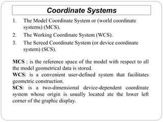
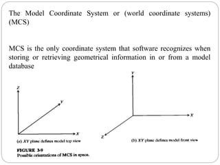
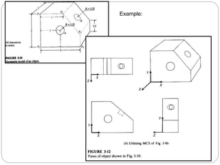
1. The model coordinate system (MCS) is the reference space where all model geometric data is stored.
2. The working coordinate system (WCS) is user-defined to facilitate geometric construction.
3. The screen coordinate system (SCS) is device-dependent with its origin at the lower left display corner.
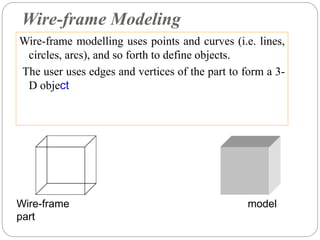
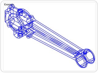
Geometric modeling refers to techniques for efficiently representing a design's geometric aspects. Approaches include wireframe modeling using points and curves, surface modeling defining objects by bounding faces, and solid modeling representing objects as solids.