Download to read offline

![International Journal of Technical Research and Applications e-ISSN: 2320-8163,
www.ijtra.com Volume 2, Issue 4 (July-Aug 2014), PP. 218-224
219 | P a g e
The Congestion is one of the main reasons of interference
because congestion means that there are huge data in channel
that increase the probability of interference with other data that
sent from other devices.
There is other factor effect on channel interference e.g.
signal strength of other devices. So if we need to avoid
interference in our network we need to take in consideration
the speed of sending data as well as control the power level
signal of other nodes. One of the main characteristic in WSN is
power consumption constraints for nodes using batteries or
energy harvesting so we need to take in consideration the
saving power.
The interference leading drop packet or block the channel
therefor we need to retransmit the lost packet or retrieve the
channel. The retransmitting packet means consuming time as
well as consuming energy. So we need to managing
interference to saving time and saving power in the
collaborative network.
The collaborative network that we used in our experiment
has many types of node so in collaborative network all nodes
starts at different time instants. The WSN need to be time
synchronized. The protocol used for time synchronization is
Timing-sync Protocol for Sensor Networks (TPSN).
In this paper, we propose two parameters (flow control and
power level) to manage interference in WSN. We evaluate our
algorithm by design collaborative network with following
devices:
PIC microcontroller node [1].
ARM microcontroller node [2].
PC node.
Wireless device used to attach with these above nodes
[3].
The reminder of the paper is organized as follows: in
section 2 we provide a background of interference solution as a
related work. In section 3 we describe the motivation behind
the manage interference. In section 4 we describe the
methodology and nodes design and the pre-algorithms used for
design the network. In section 5 we discuss the synchronization
protocol that used in our network. Section 6 show us the
interference control algorithm. The results obtain after
execution in section 7. The result’s evaluation discussed in
section 8 and concludes our paper in Section 9.
II. RELATED WORK
Wireless sensor networks will play an important role in
many applications; these applications typically fall under
sensor-based systems and autonomous systems. For example,
many wireless sensor networks monitor some aspects of the
environment and relay the processed information to a central
node. Many different wireless communication technologies,
such as ZigBee and Wi-Fi, have been witnessed recently to be
deployed in more and more applications. Thus, the cross
technology interference has drawn attention of the researchers.
Now, the WSN community has acknowledged the impact of
Wi-Fi interference on WSN applications in various settings.
Most research work done on benefit of multichannel available
in 2.4 GHz band. Some study work on interference-aware
channel assignment algorithm and protocol for multi-radio
wireless mesh networks that address this interference problem.
The proposed solution assigns channels to radios to minimize
interference within the network co-located wireless networks.
It utilizes a novel interference estimation technique
implemented at each mesh router as done in [4]. Simple local-
balancing and interference-aware channel allocation algorithms
for reducing the overall interference in the network studied [5].
Also some study don on evaluate the relative performance of
an algorithms using actual implementations on a multichannel,
multi-radio test bed. Using overall network throughput as a
metric, we show through experiments that the channel
allocation that is aware of the node’s transmission activity
performs better than the simple local balancing algorithm,
irrespective of the number of channels used for allocation as
discussed in [5].
In most paper the solution of interference either select
channel that have less use from other network or balancing the
interference among the channels. Other paper when detect the
interference simply change the channel with other.in our
solution is depend on solve the interference without depend on
changing channel, when interference occur in the collaborative
network the node with high priority take responsibility to
remove the interfacing while this node need to send data.
III. MOTIVATION
Performance of a deployed Wireless Sensor Network
(WSN) is greatly influenced by the interference it is subject to
during operation. Degradation happens because of interference
leading to packet drops, retransmissions, link instability and
inconsistent protocol behavior. Therefor to save time, save
energy and increase the Quality of Service (QoS) in network
(such as increase the throughput) we need to eliminate or
reduce the effect of interference. We have conducted
experiments that highlight the fact that interference caused by
same channel used by other devices and/or co-channel
contention significantly degrades the network performance of
protocols, especially when these devices send data in high rate
or in high power level signal. These potential sources of
interference must therefore be accounted for during the design
stage of a WSN in order to achieve acceptable network
performance. Based on these observations one solution for
increasing the network throughput of a WSN is managing
interference.
IV. METHODOLOGY AND IMPLEMENTATION
A. Network design
We designed collaborative network and these network
contain PIC, ARM and PC as a node attached with them
wireless device we assume:
1) Each node in network is known to each other.
2) Each node has own priority.
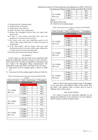
3) Two nodes (Node 1 & Node 2) communicate with each
other as shown in Fig 2.](https://image.slidesharecdn.com/ijtra140861-151027080601-lva1-app6891/85/MANAGING-INTERFERENCE-IN-COLLABORATIVE-NETWORKS-BY-FLOW-CONTROL-AND-SIGNAL-POWER-CONTROL-BASED-PRIORITY-2-320.jpg)
![International Journal of Technical Research and Applications e-ISSN: 2320-8163,
www.ijtra.com Volume 2, Issue 4 (July-Aug 2014), PP. 218-224
221 | P a g e
Second, synchronization can be used by power saving
schemes to increase network lifetime. For example, sensors
may sleep at appropriate times, and wake up when necessary.
When using power-saving modes, the nodes should sleep and
wake-up at coordinated times, such that the radio receiver of a
node is not turned when there is some data directed to it. This
requires a precise timing between sensor nodes. Scheduling
algorithms such as TDMA can be used to share the
transmission medium in the time domain to eliminate
transmission collisions and conserve energy. Thus,
synchronization is an essential part of transmission scheduling.
Timing-Sync Protocol for Sensor Networks (TPSN):
A network-wide time synchronization protocol for sensor
networks, which they call Timing-Sync Protocol for Sensor
Networks (TPSN) [6]. Their protocol works in two phases:
“level discovery phase” and “synchronization phase”. The aim
of the first phase is to create a hierarchical topology in the
network, where each node is assigned a level. Only one node is
assigned level 0, called the root node. In the second phase, a
node of level i synchronize to a node of level i-1. At the end of
the synchronization phase, all nodes are synchronized to the
root node and the network-wide synchronization is achieved.
A. Level Discovery Phase
This phase is run once at the network deployment. First a
node should be determined as the root node. The root node is
assigned level 0, and initiates the level discovery phase by
broadcasting a level discovery packet. This packet contains the
identity and level of the sender node. Upon receiving this
packet, the neighbors of the root node assign themselves level
1. Then each level 1 node broadcasts a level discovery packet
with its level and identity in the packet. Once a node is
assigned a level, it discards further incoming level discovery
packets. This broadcast chain goes on through the network, and
the phase is completed when all nodes are assigned a level.
B. Synchronization Phase
The basic building block of the synchronization phase is the
two-way message exchange between a pair of nodes. The
authors assume that the clock drift between a pair of nodes is
constant in the small time period during a single message
exchange. The propagation delay is also assumed to be
constant in both directions.
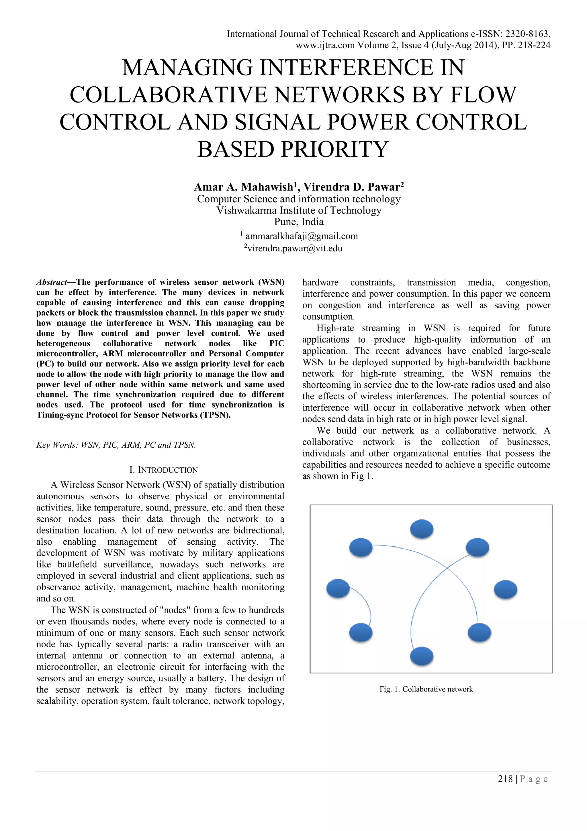
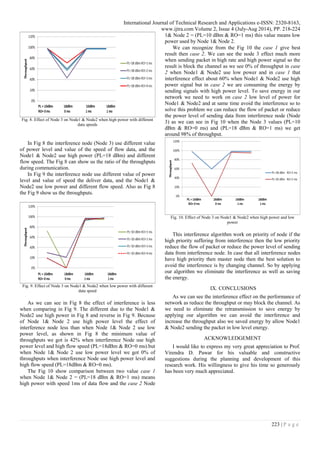
Consider a two-way message exchange between nodes A
and B as shown in Fig 7. Node A initiates the synchronization
by sending a synchronization pulse packet at T1 (according to
its local clock). This packet includes A's level number, and the
value T1. B receives this packet (according to its local clock) at
T2 = T1+Δ+ d, where Δ is the relative clock drift between the
nodes, and d is the propagation delay of the pulse. B responds
at time T3 with an acknowledgement packet, which includes
the level number of B and the values T1, T2, and T3. Then,
node A can calculate the clock drift and propagation delay as in
formula, and synchronize itself to B.
Fig. 8. Two way message exchange between a pair of nodes
VI. INTERFERENCE CONTROL ALGORITHM
Node A
T2
T1
Local time
Local time
Node B
T3
T4
ALGORITHM:
Setting parameter of nodes (Baud rate, buffer size, delay,
pin selection, I/O directions, register selection, port
initialization)
Assign: when two nodes start sending data to each other
Assign priority to all nodes one of these two node
as a master node
flow=TRUE , power=TRUE
size = No. of packet need to send
While (sending packet < size)
{
Two nodes start sending data
Master node monitors the throughput of
transmission
If (drop packets occur) THEN
{
If (flow==FALSE&&power==TRUE)
{
Master node send notification packet with
its priority value to inform other nodes in
network to reduce the power level of
packet
Power=FALSE
If(interference node priority < master
priority)
{
Reduce the level power of receive node
}
}
Else if (flow==TRUE)
{
Master node send notification packet to
inform other nodes in network to reduce
the flow rate of packet
flow=FALSE
If(interference node priority < master
priority)
{
Reduce the flow speed of receiver node
}
}
Else
{
Change Channel
}
}
}](https://image.slidesharecdn.com/ijtra140861-151027080601-lva1-app6891/85/MANAGING-INTERFERENCE-IN-COLLABORATIVE-NETWORKS-BY-FLOW-CONTROL-AND-SIGNAL-POWER-CONTROL-BASED-PRIORITY-4-320.jpg)
![International Journal of Technical Research and Applications e-ISSN: 2320-8163,
www.ijtra.com Volume 2, Issue 4 (July-Aug 2014), PP. 218-224
224 | P a g e
REFERENCES
[1] http://ww1.microchip.com/downloads/en/DeviceDoc/41
412F.pdf, PIC18F46K22 datasheet Microchip.
[2] www.nxp.com/documents/user_manual/UM10120.pdf
LPC2131/2/4/6/8 User manual Rev. 4 — 23 April 2012.
[3] http://www.digi.com/pdf/ds_xbeemultipointmodules.pdf
[4] Krishna N. Ramachandran, Elizabeth M. Belding, Kevin
C. Almeroth, Milind M. Buddhikot,” Interference- ware
Channel Assignment in Multi-Radio Wireless Mesh
Networks”, IEEE, April 2006.
[5] Vijay Raman, Nitin H. Vaidya,” Adjacent Channel
Interference Reduction in multichannel Wireless
Networks Using Intelligent Channel Allocation”, NSF
grant 06-27074, Technical Report (August 2009).
[6] Saurabh Ganeriwal Ram Kumar Mani B. Srivastava,
“Timing-sync Protocol for Sensor Networks”, ACM,
2003.](https://image.slidesharecdn.com/ijtra140861-151027080601-lva1-app6891/85/MANAGING-INTERFERENCE-IN-COLLABORATIVE-NETWORKS-BY-FLOW-CONTROL-AND-SIGNAL-POWER-CONTROL-BASED-PRIORITY-7-320.jpg)
This paper discusses managing interference in wireless sensor networks (WSNs) through flow control and signal power management. It highlights the challenges posed by interference, such as dropped packets and channel blockage, and proposes an algorithm to prioritize nodes and optimize data transmission. The proposed solution aims to enhance network performance by controlling flow and power levels during high-rate transmissions within a collaborative network.