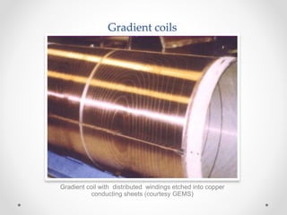
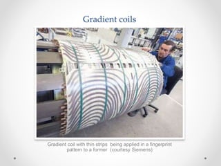
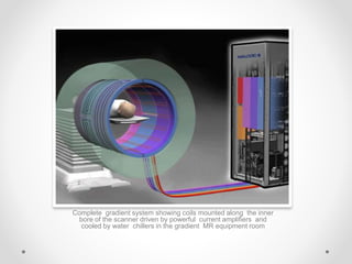
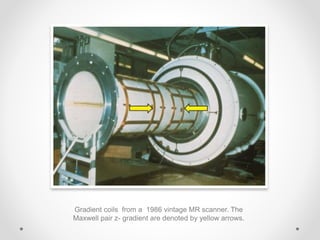
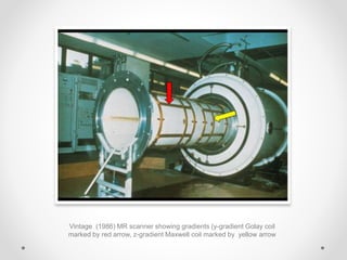
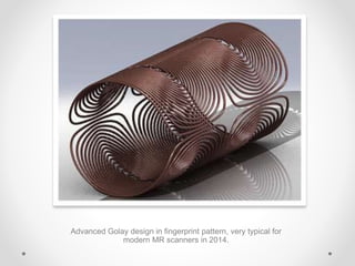
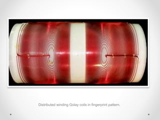
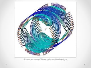
MR GRADIENT
COILS
SHAHNAWAZ KHAN
MSC.RIT 4TH SEMESTER
INTODUCTION
several processes must be completed to produce
magnetic resonance imagines, including image formation.
To complete these processes a number of system
components are required.
such components include:
• A magnet – for nuclear alignment
• A radiofrequency source- for RF excitation
• A magnetic field gradient system- for spatial encoding
• A computer system- for the image formation process and
the user interface
• an image processor- to convert ‘signals’ into images.
Magnetic field gradients
(Gradient coils)
• What are Gradient coils ?
• HISTORY
• Historically gradient coils were composed of individual wires wrapped
into cylindrical formers made of fiber glass and coated with epoxy
resin.
• Many laboratory instruments and very high- field human scanners still
use this method.
• Today, however, most widely manufactured superconducting scanners
utilize distributed windings in a “fingerprint” pattern consisting of
multiple thin metallic strips or large copper sheets etched into complex
patterns and applied to the cylinder.
• Conducting loops made of wires or foil etchings wound on a
shell with in scanner bore
• Produce calibrated distortions of main magnetic field in x, y,
z, directions
Gradient coils
Gradient coils with discrete wire windings in 7T scanner
(from human connectisome project)
Gradient coils
Gradient coil with distributed windings etched into copper
conducting sheets (courtesy GEMS)
Gradient coils
Gradient coil with thin strips being applied in a fingerprint
pattern to a former (courtesy Siemens)
Gradient coils
• By definition gradient is simply a slope, in this case a
very linear slope in magnetic strength across the imaging
volume in a particular direction. To understand how the
strength of a magnetic field can be altered, we need to
consider the factors that change the strength of a
electromagnet. They are;
• The current passing through the windings
• The number of windings in the coil
• The diameter of the wire used in the windings
• The distance or pacing between the windings
Complete gradient system showing coils mounted along the inner
bore of the scanner driven by powerful current amplifiers and
cooled by water chillers in the gradient MR equipment room
• Altering any of the first three factors would change the amplitude or
strength of a magnetic field induced around the coil uniformity.
• To slope the magnetic field (i.e. change the amplitude of the
magnetic field from one end of the coil to another), one could
theoretically alter the spacing between the loops.
• In practice, however coils tend to be more symmetrical in design and
rely on a three- terminal arrangement to achieve the gradient field.
This coil has 12 windings uniformly spaced and is attached to an
electrical terminal at each end . Current therefore flows in one
direction through coil and the resultant magnetic field direction can
be demonstrated with right hand rule, in this case left to right.
• if the above design is altered slightly to include a third terminal in the
center of the coil, the polarity of the terminal can be arranged so that
current flows in opposite directions at each end of the coil.
• This generates two magnetic fields of equal but opposite direction.
Gradient coil and main magnetic
windings
The first coil represents the main magnet, and the second
represents the Z gradient coil.
Z axis Gradient
• How do you make a z-direction gradient?
• The direction and magnitude of gradient fields can be appreciated by
using two basic principles of classical electromagnetism- Ampere’s law
and Right –hand rule.
• The strength of the gradient field is directly related to the current sent
through the gradient coils.
• The direction of the gradient field is predicted by grasping (in your
imagination!) the gradient coil with your right hand and letting your
thumb point long the path of the current.
The basic design is Maxwell coil pair- two loops
with currents travelling in opposite directions
Right hand rule
Thumb pointing along the direction of current, fingers curl
along wire in the direction induced magnetic field B.
• in all the MR scanners the z- gradient is produced using two coil
carrying current in opposite directions as shown in diagram to the
below.
• This is known as Maxwell coil configuration.
• Maxwell coils produce an incremental field that is zero at magnet
isocentre but increases linearly outward in both the +z and -z
directions. When this is added to the constant (Bₒ) field,
• The result is gradually increasing gradient along the z- axis.
Gradient coils from a 1986 vintage MR scanner. The
Maxwell pair z- gradient are denoted by yellow arrows.
X- and Y- Gradients
• How do you make X- and Y- direction gradients ?
• The design for transverse gradients used in cylindrical MR magnets is
based on a “double-saddle” coil configuration originally described in
1958 by Marcel Golay.
• The simplest form of this coil set consists of 4 inner and 4 outer arcs on
the surface of a cylinder connected by 8 straight wires running parallel
to the z-axis.
• The current along the inner arcs are primarily responsible for creating
the required gradient, while the straight wires parallel to z-axis serve as
return pathways for current and do not contribute to the gradient field.
Simplest design is by Golay; a double-saddle coil
configuration
More sophisticated “fingerprint” coils now often used
Double – saddle Golay coil configuration for producing a Y-
gradient.to produce an x gradient the coils are rotated by 90.
‫﮿‬̥̊
Vintage (1986) MR scanner showing gradients (y-gradient Golay coil
marked by red arrow, z-gradient Maxwell coil marked by yellow arrow
Advanced Golay design in fingerprint pattern, very typical for
modern MR scanners in 2014.
Distributed winding Golay coils in fingerprint pattern.
Bizarre appearing 3D computer assisted designs
GRADIENT
CHARACTERISTICS
• Each time a gradient is switched on, power is applied to the gradient
until it reaches maximum strength or amplitude and is then switched
off.
• The processional frequency of a magnetic moment is depended on
the strength it is exposed to (as determined by lamer equation).
• Therefore by changing field strength in a linear fashion using a
gradient, the processional frequency and hence phase of magnetic
moments are also altered linearly
• This is how gradients are used to spatially locate signal and re-
phase spins.
• Gradient coils are powered by gradient amplifiers.
• Faults in gradient coils or gradient amplifiers can result in geometric
distortions in MR image.
How gradients change field strength.
GRADIENT
CHARACTERICS
• Gradient strength or gradient amplitude defines how steep or
strong a particular gradient is. It is measured in mille tesla per meter
(mT/m) or gauss per centimeter G/cm.
• Gradient speed or gradient rise time defines the time it takes for a
given gradient to reach maximum amplitude. Rise time is measured
in microseconds.
• Slew rate defines the time it takes for a given gradient to reach
maximum amplitude and what that amplitude is. Slew rate is the
speed and strength of the gradient and s measured in units of mille
Tesla per meter per second (mT/m/s).
• Duty cycle defines the percentage of time that the gradient is
permitted to work. Duty cycle expressed in units of percentage(%).
• Gradient amplitude vary but typical gradient strengths are between
10mT/m, depending on the power of the gradients with in the system
• In a 10mT/m gradient system, the strength of the magnetic field
changes 10mT over each meter along the gradient field.
• The maximum amplitude or strength of a gradient is important when
good spatial resolution is required
• To achieve small voxels that are necessary for good spatial
resolution , all the three gradients must be able to achieve a high
amplitude .
• Gradient strength can be expressed in units G/cm or mT/m , where
1G/cm = 10 mT/m
Amplitude versus rise
time Gradient
• How quickly a gradient can attain a particular slope is called rise
time.
• This effects how fast a gradient can be switched on and off and this
in turn affects the scan time.
• Gradient rise times are in the order of 120 µs.
• If the rise time is reduced , time is saved within the pulse sequence,
which is then translated into shorter overall imaging times.
Graphical representation of asymmetric gradient
Balanced gradient systems
• A gradient waveform, which will act on any stationary spin on a
resonance between two consecutive RF pulses and return it to the
same phase it had before gradient were applied
• in a balanced gradient system , each gradient pulse is balanced by
an equal but opposite gradient pulse this is known as bipolar or
balanced gradient system
• during the readout, the amplitude of the lobe are limited by the
desired resolution chosen by the FOV (bandwidth and sampling
time)
• The time that the gradient is on (determined by the sampling time) is
determined by the readout/receive bandwidth.
• if this time is doubled by the application of positive and negative
lobes of the same amplitude and sampling ,time is wasted within the
pulse sequence
Balanced or bipolar gradients Asymmetric gradients
High speed gradient
• To acquire high gradient amplitude with shorter rise times,
modifications to the power can be considered
• High gradient amplitudes permit high amplitude balancing lobes,
allowing for the time saving within pulse sequences.
• High power gradients with asymmetric refocusing lobes will reduce
the time lost within the sequence and result in higher resolution
rapid images.
• High speed gradient switching necessitates high quality gradient
amplifiers
Gradient Amplifiers
• High- power audio frequency amplifiers (similar to those used for high – quality
concert sound systems) supply the current required to produce the gradient fields
• The requirement for high-peak-gradient amplitudes means that the amplifier must
be capable of generating large electrical currents through the coils
• Furthermore, the requirement for short rise and fall times means that this current
must be rapidly increasing from zero to the maximum and then back down.
• However whenever you attempt to change the current flowing through a coil a
“back- emf” is generated. The emf therefore needs to generate a sufficient driving
force voltage to overcome this back-emf.
• The capacity of the gradient amplifier to generate this voltage limits the slew rate .
• Since the electrical power required to setup a gradient is proportional the fifth
power of radius (r5) volume over which the gradient acts,
• Obtaining short rise times with the whole body sized coils necessitates substantial
amplifier capabilities.
Gradient cabnit containing 3 independent power amplifiers for
x,y,z-gradients
Eddy Currents
• The rapid switching of the gradients induces eddy currents in nearby
conducting components of the magnet cryostat.
• The field generated by eddy current combines with the
intended gradient field to create waveform distortion
which can result in image artifact and signal loss.
• Eddy current can be reduced by deliberately pre-
emphasizing the gradient wave form so that when
combined with eddy current field the resultant is close to
ideal gradient waveform.
• The pre emphasis requires extra electronic circuit that
adds additional voltage, with adjustable amplitude and
time constant.
THANK YOU

Mri gradient coils

  • 1.
  • 2.
    INTODUCTION several processes mustbe completed to produce magnetic resonance imagines, including image formation. To complete these processes a number of system components are required. such components include: • A magnet – for nuclear alignment • A radiofrequency source- for RF excitation • A magnetic field gradient system- for spatial encoding • A computer system- for the image formation process and the user interface • an image processor- to convert ‘signals’ into images.
  • 3.
    Magnetic field gradients (Gradientcoils) • What are Gradient coils ? • HISTORY • Historically gradient coils were composed of individual wires wrapped into cylindrical formers made of fiber glass and coated with epoxy resin. • Many laboratory instruments and very high- field human scanners still use this method. • Today, however, most widely manufactured superconducting scanners utilize distributed windings in a “fingerprint” pattern consisting of multiple thin metallic strips or large copper sheets etched into complex patterns and applied to the cylinder. • Conducting loops made of wires or foil etchings wound on a shell with in scanner bore • Produce calibrated distortions of main magnetic field in x, y, z, directions
  • 4.
    Gradient coils Gradient coilswith discrete wire windings in 7T scanner (from human connectisome project)
  • 5.
    Gradient coils Gradient coilwith distributed windings etched into copper conducting sheets (courtesy GEMS)
  • 6.
    Gradient coils Gradient coilwith thin strips being applied in a fingerprint pattern to a former (courtesy Siemens)
  • 7.
    Gradient coils • Bydefinition gradient is simply a slope, in this case a very linear slope in magnetic strength across the imaging volume in a particular direction. To understand how the strength of a magnetic field can be altered, we need to consider the factors that change the strength of a electromagnet. They are; • The current passing through the windings • The number of windings in the coil • The diameter of the wire used in the windings • The distance or pacing between the windings
  • 8.
    Complete gradient systemshowing coils mounted along the inner bore of the scanner driven by powerful current amplifiers and cooled by water chillers in the gradient MR equipment room
  • 9.
    • Altering anyof the first three factors would change the amplitude or strength of a magnetic field induced around the coil uniformity. • To slope the magnetic field (i.e. change the amplitude of the magnetic field from one end of the coil to another), one could theoretically alter the spacing between the loops. • In practice, however coils tend to be more symmetrical in design and rely on a three- terminal arrangement to achieve the gradient field.
  • 10.
    This coil has12 windings uniformly spaced and is attached to an electrical terminal at each end . Current therefore flows in one direction through coil and the resultant magnetic field direction can be demonstrated with right hand rule, in this case left to right.
  • 11.
    • if theabove design is altered slightly to include a third terminal in the center of the coil, the polarity of the terminal can be arranged so that current flows in opposite directions at each end of the coil. • This generates two magnetic fields of equal but opposite direction.
  • 12.
    Gradient coil andmain magnetic windings The first coil represents the main magnet, and the second represents the Z gradient coil.
  • 13.
    Z axis Gradient •How do you make a z-direction gradient? • The direction and magnitude of gradient fields can be appreciated by using two basic principles of classical electromagnetism- Ampere’s law and Right –hand rule. • The strength of the gradient field is directly related to the current sent through the gradient coils. • The direction of the gradient field is predicted by grasping (in your imagination!) the gradient coil with your right hand and letting your thumb point long the path of the current. The basic design is Maxwell coil pair- two loops with currents travelling in opposite directions
  • 14.
    Right hand rule Thumbpointing along the direction of current, fingers curl along wire in the direction induced magnetic field B.
  • 15.
    • in allthe MR scanners the z- gradient is produced using two coil carrying current in opposite directions as shown in diagram to the below. • This is known as Maxwell coil configuration. • Maxwell coils produce an incremental field that is zero at magnet isocentre but increases linearly outward in both the +z and -z directions. When this is added to the constant (Bₒ) field, • The result is gradually increasing gradient along the z- axis.
  • 16.
    Gradient coils froma 1986 vintage MR scanner. The Maxwell pair z- gradient are denoted by yellow arrows.
  • 17.
    X- and Y-Gradients • How do you make X- and Y- direction gradients ? • The design for transverse gradients used in cylindrical MR magnets is based on a “double-saddle” coil configuration originally described in 1958 by Marcel Golay. • The simplest form of this coil set consists of 4 inner and 4 outer arcs on the surface of a cylinder connected by 8 straight wires running parallel to the z-axis. • The current along the inner arcs are primarily responsible for creating the required gradient, while the straight wires parallel to z-axis serve as return pathways for current and do not contribute to the gradient field. Simplest design is by Golay; a double-saddle coil configuration More sophisticated “fingerprint” coils now often used
  • 18.
    Double – saddleGolay coil configuration for producing a Y- gradient.to produce an x gradient the coils are rotated by 90. ‫﮿‬̥̊
  • 20.
    Vintage (1986) MRscanner showing gradients (y-gradient Golay coil marked by red arrow, z-gradient Maxwell coil marked by yellow arrow
  • 21.
    Advanced Golay designin fingerprint pattern, very typical for modern MR scanners in 2014.
  • 22.
    Distributed winding Golaycoils in fingerprint pattern.
  • 23.
    Bizarre appearing 3Dcomputer assisted designs
  • 24.
    GRADIENT CHARACTERISTICS • Each timea gradient is switched on, power is applied to the gradient until it reaches maximum strength or amplitude and is then switched off. • The processional frequency of a magnetic moment is depended on the strength it is exposed to (as determined by lamer equation). • Therefore by changing field strength in a linear fashion using a gradient, the processional frequency and hence phase of magnetic moments are also altered linearly • This is how gradients are used to spatially locate signal and re- phase spins. • Gradient coils are powered by gradient amplifiers. • Faults in gradient coils or gradient amplifiers can result in geometric distortions in MR image.
  • 25.
    How gradients changefield strength.
  • 26.
    GRADIENT CHARACTERICS • Gradient strengthor gradient amplitude defines how steep or strong a particular gradient is. It is measured in mille tesla per meter (mT/m) or gauss per centimeter G/cm. • Gradient speed or gradient rise time defines the time it takes for a given gradient to reach maximum amplitude. Rise time is measured in microseconds. • Slew rate defines the time it takes for a given gradient to reach maximum amplitude and what that amplitude is. Slew rate is the speed and strength of the gradient and s measured in units of mille Tesla per meter per second (mT/m/s). • Duty cycle defines the percentage of time that the gradient is permitted to work. Duty cycle expressed in units of percentage(%).
  • 27.
    • Gradient amplitudevary but typical gradient strengths are between 10mT/m, depending on the power of the gradients with in the system • In a 10mT/m gradient system, the strength of the magnetic field changes 10mT over each meter along the gradient field. • The maximum amplitude or strength of a gradient is important when good spatial resolution is required • To achieve small voxels that are necessary for good spatial resolution , all the three gradients must be able to achieve a high amplitude . • Gradient strength can be expressed in units G/cm or mT/m , where 1G/cm = 10 mT/m
  • 28.
    Amplitude versus rise timeGradient • How quickly a gradient can attain a particular slope is called rise time. • This effects how fast a gradient can be switched on and off and this in turn affects the scan time. • Gradient rise times are in the order of 120 µs. • If the rise time is reduced , time is saved within the pulse sequence, which is then translated into shorter overall imaging times.
  • 29.
    Graphical representation ofasymmetric gradient
  • 30.
    Balanced gradient systems •A gradient waveform, which will act on any stationary spin on a resonance between two consecutive RF pulses and return it to the same phase it had before gradient were applied • in a balanced gradient system , each gradient pulse is balanced by an equal but opposite gradient pulse this is known as bipolar or balanced gradient system • during the readout, the amplitude of the lobe are limited by the desired resolution chosen by the FOV (bandwidth and sampling time) • The time that the gradient is on (determined by the sampling time) is determined by the readout/receive bandwidth. • if this time is doubled by the application of positive and negative lobes of the same amplitude and sampling ,time is wasted within the pulse sequence
  • 31.
    Balanced or bipolargradients Asymmetric gradients
  • 32.
    High speed gradient •To acquire high gradient amplitude with shorter rise times, modifications to the power can be considered • High gradient amplitudes permit high amplitude balancing lobes, allowing for the time saving within pulse sequences. • High power gradients with asymmetric refocusing lobes will reduce the time lost within the sequence and result in higher resolution rapid images. • High speed gradient switching necessitates high quality gradient amplifiers
  • 33.
    Gradient Amplifiers • High-power audio frequency amplifiers (similar to those used for high – quality concert sound systems) supply the current required to produce the gradient fields • The requirement for high-peak-gradient amplitudes means that the amplifier must be capable of generating large electrical currents through the coils • Furthermore, the requirement for short rise and fall times means that this current must be rapidly increasing from zero to the maximum and then back down. • However whenever you attempt to change the current flowing through a coil a “back- emf” is generated. The emf therefore needs to generate a sufficient driving force voltage to overcome this back-emf. • The capacity of the gradient amplifier to generate this voltage limits the slew rate . • Since the electrical power required to setup a gradient is proportional the fifth power of radius (r5) volume over which the gradient acts, • Obtaining short rise times with the whole body sized coils necessitates substantial amplifier capabilities.
  • 34.
    Gradient cabnit containing3 independent power amplifiers for x,y,z-gradients
  • 35.
    Eddy Currents • Therapid switching of the gradients induces eddy currents in nearby conducting components of the magnet cryostat. • The field generated by eddy current combines with the intended gradient field to create waveform distortion which can result in image artifact and signal loss. • Eddy current can be reduced by deliberately pre- emphasizing the gradient wave form so that when combined with eddy current field the resultant is close to ideal gradient waveform. • The pre emphasis requires extra electronic circuit that adds additional voltage, with adjustable amplitude and time constant.
  • 36.