This document discusses tool signatures and different tool geometry systems. It provides information on:
1) The objective is to explain tool signatures, how tool angles affect machining, and why understanding signatures is important.
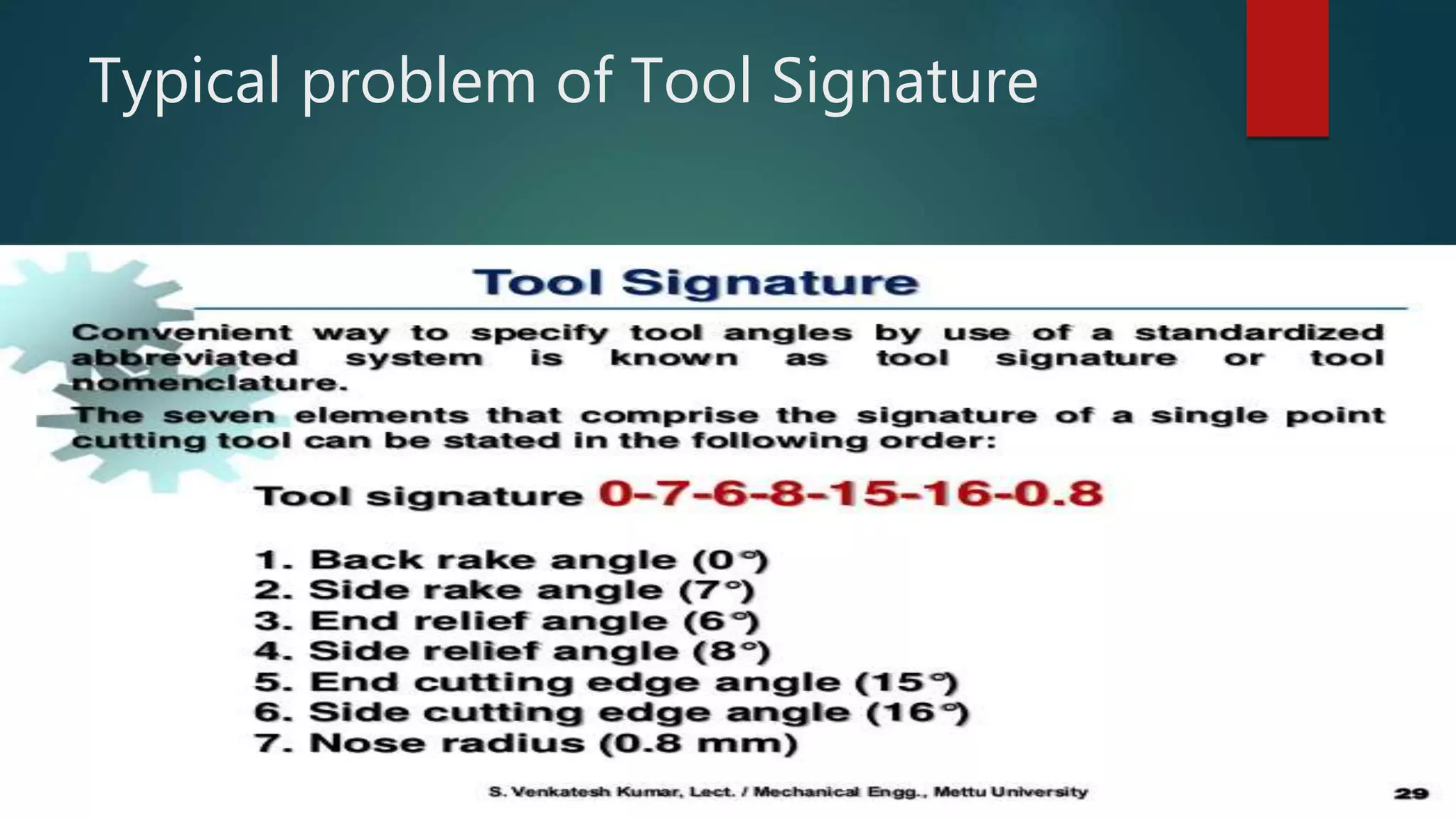
2) Tool signatures specify the key angles of a cutting tool in a standardized way. They indicate the active angles during cutting.
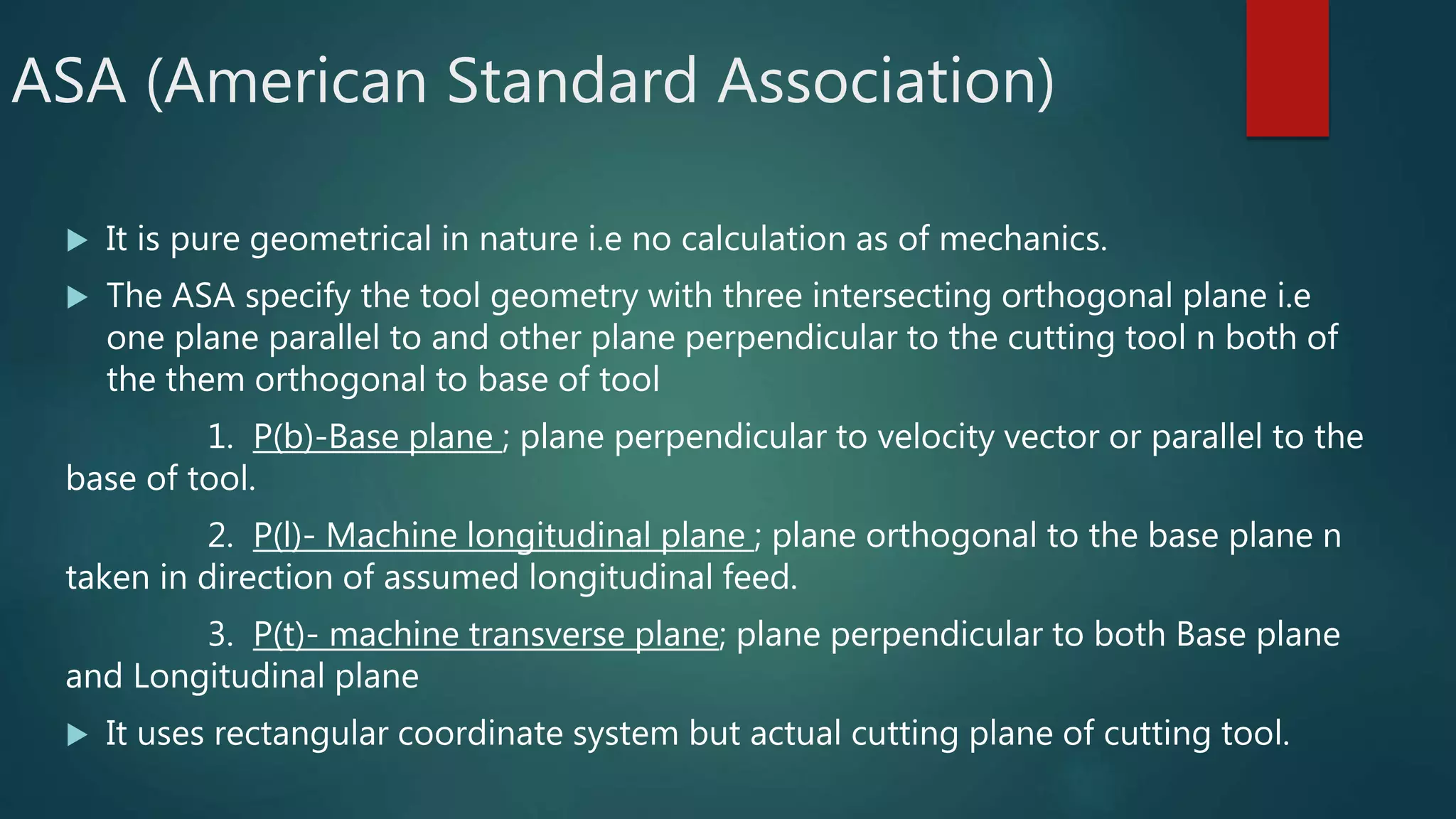
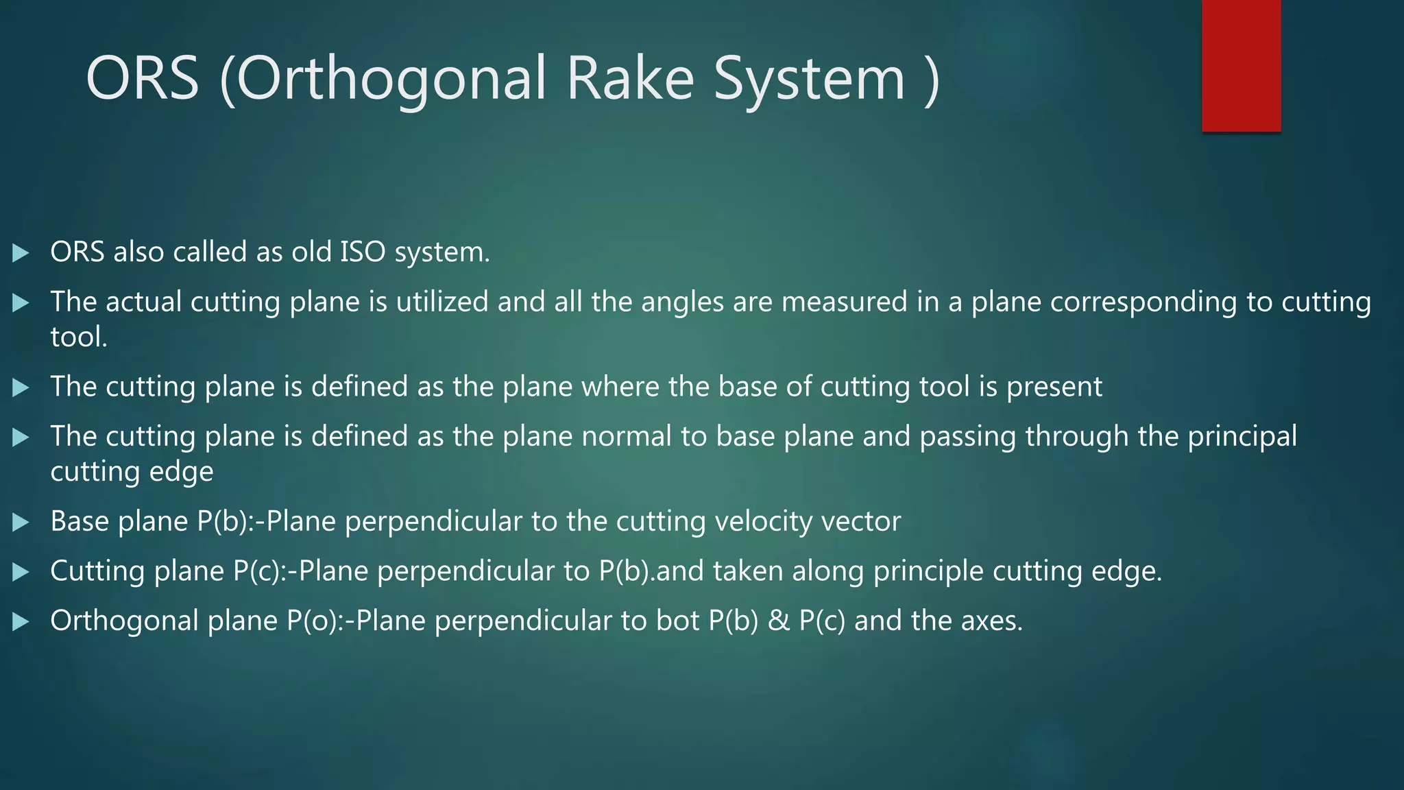
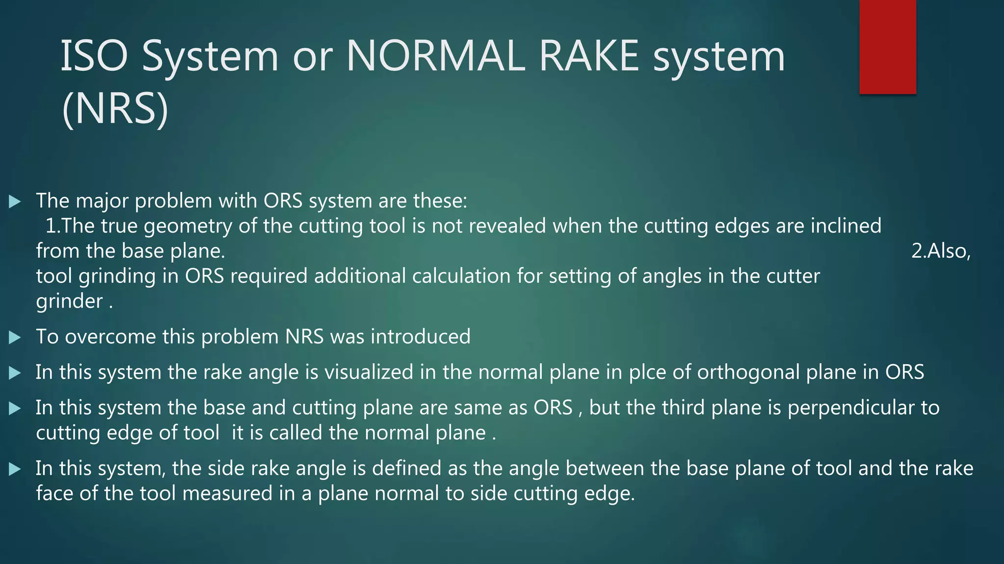
3) Three common tool geometry systems are described - ASA, ORS, and NRS. They each define tool angles differently based on different reference planes.


![Coded Agents – with UiPath SDK + LangGraph [Virtual Hands-on Workshop]](https://cdn.slidesharecdn.com/ss_thumbnails/codedagentsdeck-251215155422-5497c599-thumbnail.jpg?width=640&height=640&fit=bounds)


