SlideShare a Scribd company logo
INTRODUCTION UNIT-1
MACHINE DESIGN
 PREPARED BY:-
 SONU BANSAL
 ASST.PROF.MECHANICAL DEPARTMENT
 RNB GLOBAL UNIVERSITY BIKANER
What is Machine Design?
 Machine design is defined as the use of scientific principles, technical information and
imagination in the description of a machine or a mechanical system to perform specific
functions with maximum economy and efficiency. This definition of machine design
contains the following important features:
 A designer uses principles of basic and engineering sciences such as physics, mathematics,
statics and dynamics, thermodynamics and heat transfer, vibrations and fluid mechanics.
 The designer has technical information of the basic elements of a machine. These elements
include fastening devices, chain, belt and gear drives, bearings, oil seals and gaskets, springs,
shafts, keys, couplings, and so on.
 The designer uses his skill and imagination to produce a configuration, which is a combination
of these basic elements. However, this combination is unique and different in different
situations.
 The final outcome of the design process consists of the description of the machine. The
description is in the form of drawings of assembly and individual components.
 A design is created to satisfy a recognised need of customer. The need may be to perform a
specific function with maximum economy and efficiency.
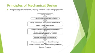
Principles of Mechanical Design
 A logical sequence of steps, usually common to all design projects,
Design Process
Step 1: market survey
Market survey is the step which is used to find out the various information regarding product. like product
design, product usefulness, product cost, product demand etc.
Step 2: Product Specifications
The first step consists of preparing a complete list of the requirements of the product. The requirements include
the output capacity of the machine, and its service life, cost and reliability. In some cases, the overall
dimensions and weight of the product are specified. For example, while designing a scooter, the list of
specifications will be as follows:
(I) Fuel consumption = 40 km/l
(ii) Maximum speed = 85 km/hr
(iii) Carrying capacity = two persons with 10 kg
luggage
(iv) Overall dimensions
Width = 700 mm
Length = 1750 mm
Height = 1000 mm
(v) Weight = 95 kg
(vi) Cost = Rs 40000 to Rs 45000
Step 3: Selection of Mechanism
After careful study of the requirements, the designer prepares rough sketches of different possible mechanisms
for the product.
Step 4: Layout of Configuration
The next step in a design procedure is to prepare a block diagram showing the general layout of the selected
confi -guration. In this step, the designer specifies the joining methods, such as riveting, bolting or welding to
connect the individual components. Rough sketches of shapes of the individual parts are prepared.
Step 5: Design of Individual Components
The design of individual components or machine elements is an important step in a design process. This stage
involves detailed stress and deflection analysis. The subjects ‘Machine Design’ or ‘Elements of Machine Design’
cover mainly
the design of machine elements or individual components of the machine.
Step 6: Preparation of Drawings
The last stage in a design process is to prepare drawings of the assembly and the individual components. On
these drawings, the material of the component, its dimensions, tolerances, surface finish grades and
machining symbols are specified.
The designer prepares two separate lists of components—standard components to be purchased directly from
the market and special components to be machined in the factory. In many cases, a prototype model is
prepared for the product and thoroughly tested before finalising the assembly drawings.
BASIC REQUIREMENTS OR DESIGN REQUIREMENTS OF MACHINE ELEMENTS
A machine consists of machine elements. Each part of a machine, which has motion with respect to some other
part, is called a machine element. It is important to note that each machine element may consist of several
parts, which are manufactured separately. The broad objective of designing a machine element is to ensure
that it preserves its operating
capacity during the stipulated service life with minimum manufacturing and operating costs. In order to
achieve this objective, the machine element should satisfy the following basic requirements:
(I) Strength: A machine part should not fail under the effect of the forces that act on it. It should have
sufficient strength to avoid failure either due to fracture or due to general yielding.
(I) Rigidity: A machine component should be rigid that is, it should not deflect or bend too much due to
forces or moments that act on it.
(iii) Wear Resistance: Wear is the main reason for putting the machine part out of order. It reduces useful
life of the component. Wear also leads to the loss of accuracy of machine tools.
(iv) Minimum Dimensions and Weight: A machine part should be sufficiently strong, rigid and wear resistant
and at the same time, with minimum possible dimensions and weight. This will result in minimum material
cost.
(v) Manufacturability: Manufacturability is the ease of fabrication and assembly. The shape and material of the machine
part should be selected in such a way that it can be produced with minimum labour cost.
(vi) Safety: The shape and dimensions of the machine parts should ensure safety to the operator of the machine. The
designer should assume the worst possible conditions and apply ‘fail-safe’ or ‘redundancy’ principles in such cases.
(vii) Conformance to Standards: A machine part should conform to the national or international standard
covering its profi le, dimensions, grade and material.
(viii) Reliability: Reliability is the probability that a machine part will perform its intended functions under
desired operating conditions over a specified period of time. A machine part should be reliable, that is, it
should perform its function satisfactorily over its lifetime.
(ix) Maintainability: A machine part should be maintainable. Maintainability is the ease with which a machine
part can be serviced or repaired.
(x) Minimum: Life-cycle Cost: Life-cycle cost of the machine part is the total cost to be paid by the purchaser
for purchasing the part and operating and maintaining it over its life span.
AESTHETIC AND ERGONOMIC CONSIDERATION IN DESIGN
 Aesthetics
 Aesthetics is concerned with how things look. This can be influenced by an objects’ appearance
and its style. The appearance of an object is the feature that people notice first.
 In some ways appearance can be very personal and is influenced by things like the materials
from which the object is made and the type of finish applied to its surface It is important that
products have visual appeal.
 In a world where many new products function in a similar way, it is often the appearance which
sells the product. Aesthetics is a pan of design which is difficult to analyse and describe in
words. However there are aspects of appearance which can be considered separately.
 External appearance is an important feature, which not only gives grace and lustre to the
product but also dominates sale in the market. This is particularly true for consumer durables
like automobiles, household appliances equipment.
CONTINUED……
 Selection of proper colour is an important consideration in product aesthetics.
The choice of colour should be compatible with the conventional ideas of the
operator. Many colours are associated with different moods and conditions.
 Like in fashion, the outward appearance of a product undergoes many
changes over the years.
 There are five basic forms—step, stream, taper, shear and sculpture. The step
form is similar to the shape of a ‘skyscraper’ or multi-storey building. This
involves shapes with a vertical accent rather than a horizontal. The stream or
streamline form is seen in automobiles and aeroplane structures. The taper
form consists of tapered blocks interlocked with tapered plinths or cylinders.
The shear form has a square outlook, which is suitable for free-standing
engineering products. The sculpture form consists of ellipsoids, paraboloids
and hyperboloids.
CONTINUED……..
 Ergonomics
 Ergonomics is defined as the relationship between man and machine and the
application of anatomical, physiological and psychological principles to solve
the problems arising from man–machine relationship. The word ‘ergonomics’
is coined from two Greek words—‘ergon’, which means ‘work’ and ‘nomos’,
which means ‘natural laws’. Ergonomics means the natural laws of work.
 From design considerations,
 the topics of ergonomic studies are as follows:
 (i) Anatomical factors in the design of a driver’s seat
 (ii) Layout of instrument dials and display panels for accurate perception by
the operators
 (iii) Design of hand levers and hand wheels
 (iv) Energy expenditure in hand and foot operations
 (v) Lighting, noise and climatic conditions in machine environment
USE OF STANDARDS IN DESIGN
 Standardization is defined as obligatory norms, to which various characteristics of a product
should conform. The characteristics include materials, dimensions and shape of the component,
method of testing and method of marking, packing and storing of the product.
 (i) Standards for Materials, their Chemical Compositions, Mechanical Properties and Heat
Treatment For example, Indian standard IS 210 specifies seven grades of grey cast iron
designated as FG 150, FG 200, FG 220, FG 260, FG 300, FG 350 and FG 400. The number
indicates ultimate tensile strength in N/mm2.
 (ii) Standards for Shapes and Dimensions of
 Commonly used Machine Elements The machine elements include bolts, screws and nuts,
rivets, belts and chains, ball and roller bearings, wire ropes, keys and splines, etc. For example,
IS 2494 (Part 1) specifies dimensions and shape of the cross-section of endless V-belts for power
transmission.
(iii) Standards for Fits, Tolerances and Surface
Finish of Component For example, selection of the type of fit for different applications is illustrated in IS 2709 on ‘Guide
for selection of fits’. The tolerances or upper and lower limits for various sizes of holes and shafts are specified in IS 919
on ‘Recommendations for limits and fits for engineering’.
(iv) Standards for Testing of Products These standards, sometimes called ‘codes’, give procedures to test the products
such as pressure vessel, boiler, crane and wire rope, where safety of the operator is an important consideration. For
example, IS 807 is a code of practice for design, manufacture, erection and testing of cranes and hoists.
(v) Standards for Engineering Drawing of
Components
For example, there is a special publication SP46 prepared by Bureau of Indian Standards on ‘Engineering
Drawing Practice for Schools and Colleges’ which covers all standards related to engineering drawing. There
are two words—standard and code-which are often used in standards.
STANDARD AND ITS TYPES:-
A standard is defined as a set of specifications for parts, materials or processes. The objective of a
standard is to reduce the variety and limit the number of items to a reasonable level. On the other hand,
a code is defined as a set of specifications for the analysis, design, manufacture, testing and erection of
the product.
The purpose of a code is to achieve a specified level of safety.
There are three types of standards used in design office. They are as follows:
(I) Company standards They are used in a particular company or a group of sister concerns.
(ii) National standards These are the IS (Bureau of Indian Standards), DIN (German), AISI or SAE (USA) or
BS (UK) standards
(iii) International standards These are prepared by the International Standards Organization (ISO).
Standardization offers the following advantages:
The reduction in types and dimensions of identical components to a rational number makes it possible to
manufacture the standard component on a mass scale in a centralised process.
For example, a specialised factory like Associated Bearing Company (SKF) manufactures ball and roller
bearings, which are required by all engineering industries. Manufacture of a standard component on mass
production basis reduces the cost.
SELECTION OF PREFERRED SIZES
In engineering design, many a times, the designer has to specify the size of the product. The ‘size’ of the
product is a general term, which includes different parameters like power transmitting capacity, load
carrying capacity, speed, dimensions of the component such as height, length and width, and volume or
weight of the product.
These parameters are expressed numerically, e.g., 5 kW, 10 kN or 1000 rpm. Often, the product is
manufactured in different sizes or models; for instance, a company may be manufacturing seven
different models of electric motors ranging from 0.5 to 50 kW to cater to the need of different
customers. Preferred numbers are used to specify the ‘sizes’ of the product in these cases.
French balloonist and engineer Charles Renard first introduced preferred numbers in the
19th century. The system is based on the use of geometric progression to develop a set of numbers.
There are five basic series2, denoted as R5, R10, R20, R40 and R80 series, which increase in steps
of 58%, 26%, 12%, 6%, and 3%, respectively. Each series has its own series factor. The series factors
are given in Table
The series is established by taking the first number and multiplying it by a series factor to get the second
number. The second number is again multiplied by a series factor to get the third number. This procedure is
continued until the complete series is built up.
DESIGNATION OF CARBON AND ALLOY STEEL
 The designation of plain carbon steel consists of the following three quantities:
 (I) a figure indicating 100 times the average percentage of carbon;
 (ii) a letter C; and
 (iii) a figure indicating 10 times the average percentage of manganese.
As an example, 55C4 indicates a plain carbon steel with 0.55% carbon and 0.4% manganese. A
steel with 0.35–0.45% carbon and 0.7–0.9% manganese is designated as 40C8.
 The designation of unalloyed free cutting steels consists of the following quantities:
 (I) a figure indicating 100 times the average percentage of carbon;
 (ii) a letter C;
 (iii) a figure indicating 10 times the average percentage of manganese;
 (iv) a symbol ‘S’, ‘Se’, ‘Te’ or ‘Pb’ depending upon the element that is present and which
 makes the steel free cutting; and
 (v) a figure indicating 100 times the average percentage of the above element that makes
 the steel free cutting.
 As an example, 25C12S14 indicates a free cutting steel with 0.25% carbon, 1.2% manganese
and 0.14% sulphur. Similarly, a free cutting steel with an average of 0.20% carbon, 1.2%
manganese and 0.15% lead is designated as 20C12Pb15.
The term ‘alloy’ steel is used for low and medium alloy steels containing total alloying
elements not exceeding 10%. The designation of alloy steels consists of the following quantities:
(I) a figure indicating 100 times the average percentage of carbon; and
(ii) chemical symbols for alloying elements each followed by the figure for its average percentage content
multiplied by a factor. The multiplying factor depends upon the alloying element. The values of this factor
are as follows:
In alloy steels, the symbol ‘Mn’ for manganese is included only if the content of manganese is equal
to or greater than 1%. The chemical symbols and their figures are arranged in descending order of
their percentage content.
The term ‘high alloy steels’ is used for alloy steels containing more than 10% of
alloying
elements. The designation of high alloy steels consists of the following quantities:
(I) a letter ‘X’;
(ii) a figure indicating 100 times the average percentage of carbon;
(iii) chemical symbol for alloying elements each followed by the figure for its average
percentage content rounded off to the nearest integer; and
(iv) chemical symbol to indicate a specially added element to attain desired
properties, if any. As an example, X15Cr25Ni12 is a high alloy steel with 0.15%
carbon, 25% chromium and 12% nickel.
SELECTION OF MATERIAL FOR STATIC AND
FATIQUE LOAD
 SELECTION OF MATERIAL:-Selection of a proper material for the machine component
is one of the most important steps in the process of machine design. The best material
is one which will serve the desired purpose at minimum cost.
 (I) Availability The material should be readily available in the market, in large enough
quantities to meet the requirement. Cast iron and aluminium alloys are always
available in abundance while shortage of lead and copper alloys is a common
experience.
 (ii) Cost For every application, there is a limiting cost beyond which the designer
cannot go. When this limit is exceeded, the designer has to consider other alternative
materials. In cost analysis, there are two factors, namely, cost of material and the cost
of processing the material into finished goods.
 (iii) Mechanical Properties Mechanical properties are the most important technical
factor governing the selection of material. They include strength under static and
fluctuating loads, elasticity, plasticity, stiffness, resilience, toughness, ductility,
malleability and hardness. Depending upon the service conditions and the functional
requirement, different mechanical properties are considered and a suitable material is
selected.
(iv) Manufacturing Considerations In some applications, machinability of material is
an
important consideration in selection. Sometimes, an expensive material is more
economical than a low priced one, which is difficult to machine. Free cutting steels
have excellent machinability, which is an important factor in their selection for high
strength bolts, axles and shafts. Where the product is of complex shape, cast
ability or ability of the molten metal to flow into intricate passages is the criterion of
material selection. In fabricated assemblies of plates and rods, weldability
becomes the governing factor. The manufacturing processes, such as casting,
forging, extrusion, welding and machining govern the selection of material. Past
experience is a good guide for the selection of material. However, a designer
should not overlook the possibilities of new materials.

More Related Content

What's hot

Theory of machines: Shaper Feed Mechanism
Theory of machines: Shaper Feed MechanismTheory of machines: Shaper Feed Mechanism
Theory of machines: Shaper Feed Mechanism
Mohamed Abd El-Moniem
 
Unit 2 Machinability, Cutting Fluids, Tool Life & Wear, Tool Materials
Unit 2 Machinability, Cutting Fluids, Tool Life & Wear, Tool MaterialsUnit 2 Machinability, Cutting Fluids, Tool Life & Wear, Tool Materials
Unit 2 Machinability, Cutting Fluids, Tool Life & Wear, Tool Materials
Mechbytes
 
Unit 2 Design Of Shafts Keys and Couplings
Unit 2 Design Of Shafts Keys and CouplingsUnit 2 Design Of Shafts Keys and Couplings
Unit 2 Design Of Shafts Keys and Couplings
Mahesh Shinde
 
Broaching machine
Broaching machineBroaching machine
Broaching machine
Chintan Mehta
 
Tool wear, tool life & machinability
Tool wear, tool life & machinabilityTool wear, tool life & machinability
Tool wear, tool life & machinability
DENNY OTTARACKAL
 
DESIGN AGAINST FLUCTUATING LOAD
DESIGN AGAINST FLUCTUATING LOADDESIGN AGAINST FLUCTUATING LOAD
DESIGN AGAINST FLUCTUATING LOAD
Priyank Gandhi
 
Module 4 gear trains
Module 4 gear trainsModule 4 gear trains
Module 4 gear trains
taruian
 
Selection of grinding wheels and their conditioning
Selection of grinding wheels and  their conditioningSelection of grinding wheels and  their conditioning
Selection of grinding wheels and their conditioning
Yuga Aravind Kumar
 
Unit 4 Design of Power Screw and Screw Jack
Unit 4 Design of Power Screw and Screw JackUnit 4 Design of Power Screw and Screw Jack
Unit 4 Design of Power Screw and Screw Jack
Mahesh Shinde
 
Machining operations and machine tools
Machining operations and machine toolsMachining operations and machine tools
Machining operations and machine tools
Muhammad Muddassir
 
Gear finishing processes
Gear finishing processesGear finishing processes
Gear finishing processes
Mechbytes
 
Chip formation and types
Chip formation and typesChip formation and types
Chip formation and types
KANNANS94
 
Machine Tools
Machine ToolsMachine Tools
Machine Tools
rgbimbochamp
 
Design of Springs
Design of SpringsDesign of Springs
Design of Springs
SurajKumarChand1
 
24 cnc machine feedback devices
24 cnc machine feedback devices24 cnc machine feedback devices
24 cnc machine feedback devicesJupira Silva
 
Design of Welded Joint
Design of Welded JointDesign of Welded Joint
Design of Welded Joint
Manish Kumar
 
Cncpresentation CNC lathe machine
Cncpresentation CNC lathe machineCncpresentation CNC lathe machine
Cncpresentation CNC lathe machine
Haseeb Butt
 
Fundamentals of machine design.pdf
Fundamentals of machine design.pdfFundamentals of machine design.pdf
Fundamentals of machine design.pdf
CHINNARASUK
 
Spur gears
Spur gearsSpur gears
MACHINE DESIGN QUESTION BANK ...
MACHINE DESIGN QUESTION BANK                                                 ...MACHINE DESIGN QUESTION BANK                                                 ...
MACHINE DESIGN QUESTION BANK ...
musadoto
 

What's hot (20)

Theory of machines: Shaper Feed Mechanism
Theory of machines: Shaper Feed MechanismTheory of machines: Shaper Feed Mechanism
Theory of machines: Shaper Feed Mechanism
 
Unit 2 Machinability, Cutting Fluids, Tool Life & Wear, Tool Materials
Unit 2 Machinability, Cutting Fluids, Tool Life & Wear, Tool MaterialsUnit 2 Machinability, Cutting Fluids, Tool Life & Wear, Tool Materials
Unit 2 Machinability, Cutting Fluids, Tool Life & Wear, Tool Materials
 
Unit 2 Design Of Shafts Keys and Couplings
Unit 2 Design Of Shafts Keys and CouplingsUnit 2 Design Of Shafts Keys and Couplings
Unit 2 Design Of Shafts Keys and Couplings
 
Broaching machine
Broaching machineBroaching machine
Broaching machine
 
Tool wear, tool life & machinability
Tool wear, tool life & machinabilityTool wear, tool life & machinability
Tool wear, tool life & machinability
 
DESIGN AGAINST FLUCTUATING LOAD
DESIGN AGAINST FLUCTUATING LOADDESIGN AGAINST FLUCTUATING LOAD
DESIGN AGAINST FLUCTUATING LOAD
 
Module 4 gear trains
Module 4 gear trainsModule 4 gear trains
Module 4 gear trains
 
Selection of grinding wheels and their conditioning
Selection of grinding wheels and  their conditioningSelection of grinding wheels and  their conditioning
Selection of grinding wheels and their conditioning
 
Unit 4 Design of Power Screw and Screw Jack
Unit 4 Design of Power Screw and Screw JackUnit 4 Design of Power Screw and Screw Jack
Unit 4 Design of Power Screw and Screw Jack
 
Machining operations and machine tools
Machining operations and machine toolsMachining operations and machine tools
Machining operations and machine tools
 
Gear finishing processes
Gear finishing processesGear finishing processes
Gear finishing processes
 
Chip formation and types
Chip formation and typesChip formation and types
Chip formation and types
 
Machine Tools
Machine ToolsMachine Tools
Machine Tools
 
Design of Springs
Design of SpringsDesign of Springs
Design of Springs
 
24 cnc machine feedback devices
24 cnc machine feedback devices24 cnc machine feedback devices
24 cnc machine feedback devices
 
Design of Welded Joint
Design of Welded JointDesign of Welded Joint
Design of Welded Joint
 
Cncpresentation CNC lathe machine
Cncpresentation CNC lathe machineCncpresentation CNC lathe machine
Cncpresentation CNC lathe machine
 
Fundamentals of machine design.pdf
Fundamentals of machine design.pdfFundamentals of machine design.pdf
Fundamentals of machine design.pdf
 
Spur gears
Spur gearsSpur gears
Spur gears
 
MACHINE DESIGN QUESTION BANK ...
MACHINE DESIGN QUESTION BANK                                                 ...MACHINE DESIGN QUESTION BANK                                                 ...
MACHINE DESIGN QUESTION BANK ...
 

Similar to machine design Introduction unit-1

DESIGN OF MACHINE ELEMENTS NOTES.PDF SHARE
DESIGN OF MACHINE ELEMENTS NOTES.PDF SHAREDESIGN OF MACHINE ELEMENTS NOTES.PDF SHARE
DESIGN OF MACHINE ELEMENTS NOTES.PDF SHARE
SelvaBabu2
 
Design ppt new.pptx
Design ppt new.pptxDesign ppt new.pptx
Design ppt new.pptx
DemelashGindo1
 
MD-I UNIT-1 (TY A+B).pptx
MD-I   UNIT-1 (TY A+B).pptxMD-I   UNIT-1 (TY A+B).pptx
MD-I UNIT-1 (TY A+B).pptx
Sohamgaud
 
UNIT-1.pptx
UNIT-1.pptxUNIT-1.pptx
UNIT-1.pptx
Praveen Kumar
 
Chapter 1 design stages
Chapter 1  design stagesChapter 1  design stages
Chapter 1 design stages
BlessingMurapa1
 
Machine Design – I.pdf
Machine Design – I.pdfMachine Design – I.pdf
Machine Design – I.pdf
OmkarBakare1
 
Unit-I Theory.ppt
Unit-I Theory.pptUnit-I Theory.ppt
Unit-I Theory.ppt
001NitinKumar
 
1 a. Introduction design of machine element
1 a. Introduction   design of machine element1 a. Introduction   design of machine element
1 a. Introduction design of machine element
Dr.R. SELVAM
 
Design of machine_members-i
Design of machine_members-iDesign of machine_members-i
Design of machine_members-i
Ravindraraj
 
Jigs & Fixtures
Jigs & FixturesJigs & Fixtures
ACE305: Aircraft Components Design and Manufacture
ACE305: Aircraft Components Design and ManufactureACE305: Aircraft Components Design and Manufacture
ACE305: Aircraft Components Design and Manufacture
Dr Mohamed Elfarran
 
IRJET- Design and Development Pedal Operated Multi-Crop Thresher with Vibrati...
IRJET- Design and Development Pedal Operated Multi-Crop Thresher with Vibrati...IRJET- Design and Development Pedal Operated Multi-Crop Thresher with Vibrati...
IRJET- Design and Development Pedal Operated Multi-Crop Thresher with Vibrati...
IRJET Journal
 
Introduction to machine design |1st unit|
Introduction to machine design |1st unit|Introduction to machine design |1st unit|
Introduction to machine design |1st unit|
divakar kumar Choudhary
 
IRJET- Design and Development of Fixture for Skid Sole of Rotavator
IRJET- Design and Development of Fixture for Skid Sole of RotavatorIRJET- Design and Development of Fixture for Skid Sole of Rotavator
IRJET- Design and Development of Fixture for Skid Sole of Rotavator
IRJET Journal
 
Lecture 1 and 2
Lecture 1 and 2Lecture 1 and 2
Lecture 1 and 2
Serajul Haque
 
IRJET- Design Development and Analysis of Low Pressure Bladeless Turbine
IRJET- Design Development and Analysis of Low Pressure Bladeless TurbineIRJET- Design Development and Analysis of Low Pressure Bladeless Turbine
IRJET- Design Development and Analysis of Low Pressure Bladeless Turbine
IRJET Journal
 
O0333075085
O0333075085O0333075085
O0333075085
theijes
 
OPTIMIZED MANUFACTURING PROCESSES FOR COOLER TANK
OPTIMIZED MANUFACTURING PROCESSES FOR COOLER TANKOPTIMIZED MANUFACTURING PROCESSES FOR COOLER TANK
OPTIMIZED MANUFACTURING PROCESSES FOR COOLER TANK
Ijripublishers Ijri
 
OPTIMIZED MANUFACTURING PROCESSES FOR COOLER TANK
OPTIMIZED MANUFACTURING PROCESSES FOR COOLER TANKOPTIMIZED MANUFACTURING PROCESSES FOR COOLER TANK
OPTIMIZED MANUFACTURING PROCESSES FOR COOLER TANK
Ijripublishers Ijri
 

Similar to machine design Introduction unit-1 (20)

DESIGN OF MACHINE ELEMENTS NOTES.PDF SHARE
DESIGN OF MACHINE ELEMENTS NOTES.PDF SHAREDESIGN OF MACHINE ELEMENTS NOTES.PDF SHARE
DESIGN OF MACHINE ELEMENTS NOTES.PDF SHARE
 
Design ppt new.pptx
Design ppt new.pptxDesign ppt new.pptx
Design ppt new.pptx
 
MD-I UNIT-1 (TY A+B).pptx
MD-I   UNIT-1 (TY A+B).pptxMD-I   UNIT-1 (TY A+B).pptx
MD-I UNIT-1 (TY A+B).pptx
 
UNIT-1.pptx
UNIT-1.pptxUNIT-1.pptx
UNIT-1.pptx
 
Chapter 1 design stages
Chapter 1  design stagesChapter 1  design stages
Chapter 1 design stages
 
Machine Design – I.pdf
Machine Design – I.pdfMachine Design – I.pdf
Machine Design – I.pdf
 
Unit-I Theory.ppt
Unit-I Theory.pptUnit-I Theory.ppt
Unit-I Theory.ppt
 
1 a. Introduction design of machine element
1 a. Introduction   design of machine element1 a. Introduction   design of machine element
1 a. Introduction design of machine element
 
Design of machine_members-i
Design of machine_members-iDesign of machine_members-i
Design of machine_members-i
 
Jigs & Fixtures
Jigs & FixturesJigs & Fixtures
Jigs & Fixtures
 
ACE305: Aircraft Components Design and Manufacture
ACE305: Aircraft Components Design and ManufactureACE305: Aircraft Components Design and Manufacture
ACE305: Aircraft Components Design and Manufacture
 
IRJET- Design and Development Pedal Operated Multi-Crop Thresher with Vibrati...
IRJET- Design and Development Pedal Operated Multi-Crop Thresher with Vibrati...IRJET- Design and Development Pedal Operated Multi-Crop Thresher with Vibrati...
IRJET- Design and Development Pedal Operated Multi-Crop Thresher with Vibrati...
 
Introduction to machine design |1st unit|
Introduction to machine design |1st unit|Introduction to machine design |1st unit|
Introduction to machine design |1st unit|
 
IRJET- Design and Development of Fixture for Skid Sole of Rotavator
IRJET- Design and Development of Fixture for Skid Sole of RotavatorIRJET- Design and Development of Fixture for Skid Sole of Rotavator
IRJET- Design and Development of Fixture for Skid Sole of Rotavator
 
Lecture 1 and 2
Lecture 1 and 2Lecture 1 and 2
Lecture 1 and 2
 
IRJET- Design Development and Analysis of Low Pressure Bladeless Turbine
IRJET- Design Development and Analysis of Low Pressure Bladeless TurbineIRJET- Design Development and Analysis of Low Pressure Bladeless Turbine
IRJET- Design Development and Analysis of Low Pressure Bladeless Turbine
 
O0333075085
O0333075085O0333075085
O0333075085
 
OPTIMIZED MANUFACTURING PROCESSES FOR COOLER TANK
OPTIMIZED MANUFACTURING PROCESSES FOR COOLER TANKOPTIMIZED MANUFACTURING PROCESSES FOR COOLER TANK
OPTIMIZED MANUFACTURING PROCESSES FOR COOLER TANK
 
OPTIMIZED MANUFACTURING PROCESSES FOR COOLER TANK
OPTIMIZED MANUFACTURING PROCESSES FOR COOLER TANKOPTIMIZED MANUFACTURING PROCESSES FOR COOLER TANK
OPTIMIZED MANUFACTURING PROCESSES FOR COOLER TANK
 
Riv2
Riv2Riv2
Riv2
 

Recently uploaded

Industrial Training at Shahjalal Fertilizer Company Limited (SFCL)
Industrial Training at Shahjalal Fertilizer Company Limited (SFCL)Industrial Training at Shahjalal Fertilizer Company Limited (SFCL)
Industrial Training at Shahjalal Fertilizer Company Limited (SFCL)
MdTanvirMahtab2
 
Gen AI Study Jams _ For the GDSC Leads in India.pdf
Gen AI Study Jams _ For the GDSC Leads in India.pdfGen AI Study Jams _ For the GDSC Leads in India.pdf
Gen AI Study Jams _ For the GDSC Leads in India.pdf
gdsczhcet
 
Fundamentals of Electric Drives and its applications.pptx
Fundamentals of Electric Drives and its applications.pptxFundamentals of Electric Drives and its applications.pptx
Fundamentals of Electric Drives and its applications.pptx
manasideore6
 
AP LAB PPT.pdf ap lab ppt no title specific
AP LAB PPT.pdf ap lab ppt no title specificAP LAB PPT.pdf ap lab ppt no title specific
AP LAB PPT.pdf ap lab ppt no title specific
BrazilAccount1
 
RAT: Retrieval Augmented Thoughts Elicit Context-Aware Reasoning in Long-Hori...
RAT: Retrieval Augmented Thoughts Elicit Context-Aware Reasoning in Long-Hori...RAT: Retrieval Augmented Thoughts Elicit Context-Aware Reasoning in Long-Hori...
RAT: Retrieval Augmented Thoughts Elicit Context-Aware Reasoning in Long-Hori...
thanhdowork
 
Hybrid optimization of pumped hydro system and solar- Engr. Abdul-Azeez.pdf
Hybrid optimization of pumped hydro system and solar- Engr. Abdul-Azeez.pdfHybrid optimization of pumped hydro system and solar- Engr. Abdul-Azeez.pdf
Hybrid optimization of pumped hydro system and solar- Engr. Abdul-Azeez.pdf
fxintegritypublishin
 
weather web application report.pdf
weather web application report.pdfweather web application report.pdf
weather web application report.pdf
Pratik Pawar
 
block diagram and signal flow graph representation
block diagram and signal flow graph representationblock diagram and signal flow graph representation
block diagram and signal flow graph representation
Divya Somashekar
 
NO1 Uk best vashikaran specialist in delhi vashikaran baba near me online vas...
NO1 Uk best vashikaran specialist in delhi vashikaran baba near me online vas...NO1 Uk best vashikaran specialist in delhi vashikaran baba near me online vas...
NO1 Uk best vashikaran specialist in delhi vashikaran baba near me online vas...
Amil Baba Dawood bangali
 
ethical hacking in wireless-hacking1.ppt
ethical hacking in wireless-hacking1.pptethical hacking in wireless-hacking1.ppt
ethical hacking in wireless-hacking1.ppt
Jayaprasanna4
 
ASME IX(9) 2007 Full Version .pdf
ASME IX(9)  2007 Full Version       .pdfASME IX(9)  2007 Full Version       .pdf
ASME IX(9) 2007 Full Version .pdf
AhmedHussein950959
 
space technology lecture notes on satellite
space technology lecture notes on satellitespace technology lecture notes on satellite
space technology lecture notes on satellite
ongomchris
 
road safety engineering r s e unit 3.pdf
road safety engineering  r s e unit 3.pdfroad safety engineering  r s e unit 3.pdf
road safety engineering r s e unit 3.pdf
VENKATESHvenky89705
 
Investor-Presentation-Q1FY2024 investor presentation document.pptx
Investor-Presentation-Q1FY2024 investor presentation document.pptxInvestor-Presentation-Q1FY2024 investor presentation document.pptx
Investor-Presentation-Q1FY2024 investor presentation document.pptx
AmarGB2
 
Nuclear Power Economics and Structuring 2024
Nuclear Power Economics and Structuring 2024Nuclear Power Economics and Structuring 2024
Nuclear Power Economics and Structuring 2024
Massimo Talia
 
ethical hacking-mobile hacking methods.ppt
ethical hacking-mobile hacking methods.pptethical hacking-mobile hacking methods.ppt
ethical hacking-mobile hacking methods.ppt
Jayaprasanna4
 
Runway Orientation Based on the Wind Rose Diagram.pptx
Runway Orientation Based on the Wind Rose Diagram.pptxRunway Orientation Based on the Wind Rose Diagram.pptx
Runway Orientation Based on the Wind Rose Diagram.pptx
SupreethSP4
 
Standard Reomte Control Interface - Neometrix
Standard Reomte Control Interface - NeometrixStandard Reomte Control Interface - Neometrix
Standard Reomte Control Interface - Neometrix
Neometrix_Engineering_Pvt_Ltd
 
Final project report on grocery store management system..pdf
Final project report on grocery store management system..pdfFinal project report on grocery store management system..pdf
Final project report on grocery store management system..pdf
Kamal Acharya
 
Architectural Portfolio Sean Lockwood
Architectural Portfolio Sean LockwoodArchitectural Portfolio Sean Lockwood
Architectural Portfolio Sean Lockwood
seandesed
 

Recently uploaded (20)

Industrial Training at Shahjalal Fertilizer Company Limited (SFCL)
Industrial Training at Shahjalal Fertilizer Company Limited (SFCL)Industrial Training at Shahjalal Fertilizer Company Limited (SFCL)
Industrial Training at Shahjalal Fertilizer Company Limited (SFCL)
 
Gen AI Study Jams _ For the GDSC Leads in India.pdf
Gen AI Study Jams _ For the GDSC Leads in India.pdfGen AI Study Jams _ For the GDSC Leads in India.pdf
Gen AI Study Jams _ For the GDSC Leads in India.pdf
 
Fundamentals of Electric Drives and its applications.pptx
Fundamentals of Electric Drives and its applications.pptxFundamentals of Electric Drives and its applications.pptx
Fundamentals of Electric Drives and its applications.pptx
 
AP LAB PPT.pdf ap lab ppt no title specific
AP LAB PPT.pdf ap lab ppt no title specificAP LAB PPT.pdf ap lab ppt no title specific
AP LAB PPT.pdf ap lab ppt no title specific
 
RAT: Retrieval Augmented Thoughts Elicit Context-Aware Reasoning in Long-Hori...
RAT: Retrieval Augmented Thoughts Elicit Context-Aware Reasoning in Long-Hori...RAT: Retrieval Augmented Thoughts Elicit Context-Aware Reasoning in Long-Hori...
RAT: Retrieval Augmented Thoughts Elicit Context-Aware Reasoning in Long-Hori...
 
Hybrid optimization of pumped hydro system and solar- Engr. Abdul-Azeez.pdf
Hybrid optimization of pumped hydro system and solar- Engr. Abdul-Azeez.pdfHybrid optimization of pumped hydro system and solar- Engr. Abdul-Azeez.pdf
Hybrid optimization of pumped hydro system and solar- Engr. Abdul-Azeez.pdf
 
weather web application report.pdf
weather web application report.pdfweather web application report.pdf
weather web application report.pdf
 
block diagram and signal flow graph representation
block diagram and signal flow graph representationblock diagram and signal flow graph representation
block diagram and signal flow graph representation
 
NO1 Uk best vashikaran specialist in delhi vashikaran baba near me online vas...
NO1 Uk best vashikaran specialist in delhi vashikaran baba near me online vas...NO1 Uk best vashikaran specialist in delhi vashikaran baba near me online vas...
NO1 Uk best vashikaran specialist in delhi vashikaran baba near me online vas...
 
ethical hacking in wireless-hacking1.ppt
ethical hacking in wireless-hacking1.pptethical hacking in wireless-hacking1.ppt
ethical hacking in wireless-hacking1.ppt
 
ASME IX(9) 2007 Full Version .pdf
ASME IX(9)  2007 Full Version       .pdfASME IX(9)  2007 Full Version       .pdf
ASME IX(9) 2007 Full Version .pdf
 
space technology lecture notes on satellite
space technology lecture notes on satellitespace technology lecture notes on satellite
space technology lecture notes on satellite
 
road safety engineering r s e unit 3.pdf
road safety engineering  r s e unit 3.pdfroad safety engineering  r s e unit 3.pdf
road safety engineering r s e unit 3.pdf
 
Investor-Presentation-Q1FY2024 investor presentation document.pptx
Investor-Presentation-Q1FY2024 investor presentation document.pptxInvestor-Presentation-Q1FY2024 investor presentation document.pptx
Investor-Presentation-Q1FY2024 investor presentation document.pptx
 
Nuclear Power Economics and Structuring 2024
Nuclear Power Economics and Structuring 2024Nuclear Power Economics and Structuring 2024
Nuclear Power Economics and Structuring 2024
 
ethical hacking-mobile hacking methods.ppt
ethical hacking-mobile hacking methods.pptethical hacking-mobile hacking methods.ppt
ethical hacking-mobile hacking methods.ppt
 
Runway Orientation Based on the Wind Rose Diagram.pptx
Runway Orientation Based on the Wind Rose Diagram.pptxRunway Orientation Based on the Wind Rose Diagram.pptx
Runway Orientation Based on the Wind Rose Diagram.pptx
 
Standard Reomte Control Interface - Neometrix
Standard Reomte Control Interface - NeometrixStandard Reomte Control Interface - Neometrix
Standard Reomte Control Interface - Neometrix
 
Final project report on grocery store management system..pdf
Final project report on grocery store management system..pdfFinal project report on grocery store management system..pdf
Final project report on grocery store management system..pdf
 
Architectural Portfolio Sean Lockwood
Architectural Portfolio Sean LockwoodArchitectural Portfolio Sean Lockwood
Architectural Portfolio Sean Lockwood
 

machine design Introduction unit-1

  • 1. INTRODUCTION UNIT-1 MACHINE DESIGN  PREPARED BY:-  SONU BANSAL  ASST.PROF.MECHANICAL DEPARTMENT  RNB GLOBAL UNIVERSITY BIKANER
  • 2. What is Machine Design?  Machine design is defined as the use of scientific principles, technical information and imagination in the description of a machine or a mechanical system to perform specific functions with maximum economy and efficiency. This definition of machine design contains the following important features:  A designer uses principles of basic and engineering sciences such as physics, mathematics, statics and dynamics, thermodynamics and heat transfer, vibrations and fluid mechanics.  The designer has technical information of the basic elements of a machine. These elements include fastening devices, chain, belt and gear drives, bearings, oil seals and gaskets, springs, shafts, keys, couplings, and so on.  The designer uses his skill and imagination to produce a configuration, which is a combination of these basic elements. However, this combination is unique and different in different situations.  The final outcome of the design process consists of the description of the machine. The description is in the form of drawings of assembly and individual components.  A design is created to satisfy a recognised need of customer. The need may be to perform a specific function with maximum economy and efficiency.
  • 3. Principles of Mechanical Design  A logical sequence of steps, usually common to all design projects, Design Process
  • 4. Step 1: market survey Market survey is the step which is used to find out the various information regarding product. like product design, product usefulness, product cost, product demand etc. Step 2: Product Specifications The first step consists of preparing a complete list of the requirements of the product. The requirements include the output capacity of the machine, and its service life, cost and reliability. In some cases, the overall dimensions and weight of the product are specified. For example, while designing a scooter, the list of specifications will be as follows: (I) Fuel consumption = 40 km/l (ii) Maximum speed = 85 km/hr (iii) Carrying capacity = two persons with 10 kg luggage (iv) Overall dimensions Width = 700 mm Length = 1750 mm Height = 1000 mm (v) Weight = 95 kg (vi) Cost = Rs 40000 to Rs 45000
  • 5. Step 3: Selection of Mechanism After careful study of the requirements, the designer prepares rough sketches of different possible mechanisms for the product. Step 4: Layout of Configuration The next step in a design procedure is to prepare a block diagram showing the general layout of the selected confi -guration. In this step, the designer specifies the joining methods, such as riveting, bolting or welding to connect the individual components. Rough sketches of shapes of the individual parts are prepared. Step 5: Design of Individual Components The design of individual components or machine elements is an important step in a design process. This stage involves detailed stress and deflection analysis. The subjects ‘Machine Design’ or ‘Elements of Machine Design’ cover mainly the design of machine elements or individual components of the machine. Step 6: Preparation of Drawings The last stage in a design process is to prepare drawings of the assembly and the individual components. On these drawings, the material of the component, its dimensions, tolerances, surface finish grades and machining symbols are specified. The designer prepares two separate lists of components—standard components to be purchased directly from the market and special components to be machined in the factory. In many cases, a prototype model is prepared for the product and thoroughly tested before finalising the assembly drawings.
  • 6. BASIC REQUIREMENTS OR DESIGN REQUIREMENTS OF MACHINE ELEMENTS A machine consists of machine elements. Each part of a machine, which has motion with respect to some other part, is called a machine element. It is important to note that each machine element may consist of several parts, which are manufactured separately. The broad objective of designing a machine element is to ensure that it preserves its operating capacity during the stipulated service life with minimum manufacturing and operating costs. In order to achieve this objective, the machine element should satisfy the following basic requirements: (I) Strength: A machine part should not fail under the effect of the forces that act on it. It should have sufficient strength to avoid failure either due to fracture or due to general yielding. (I) Rigidity: A machine component should be rigid that is, it should not deflect or bend too much due to forces or moments that act on it. (iii) Wear Resistance: Wear is the main reason for putting the machine part out of order. It reduces useful life of the component. Wear also leads to the loss of accuracy of machine tools. (iv) Minimum Dimensions and Weight: A machine part should be sufficiently strong, rigid and wear resistant and at the same time, with minimum possible dimensions and weight. This will result in minimum material cost.
  • 7. (v) Manufacturability: Manufacturability is the ease of fabrication and assembly. The shape and material of the machine part should be selected in such a way that it can be produced with minimum labour cost. (vi) Safety: The shape and dimensions of the machine parts should ensure safety to the operator of the machine. The designer should assume the worst possible conditions and apply ‘fail-safe’ or ‘redundancy’ principles in such cases. (vii) Conformance to Standards: A machine part should conform to the national or international standard covering its profi le, dimensions, grade and material. (viii) Reliability: Reliability is the probability that a machine part will perform its intended functions under desired operating conditions over a specified period of time. A machine part should be reliable, that is, it should perform its function satisfactorily over its lifetime. (ix) Maintainability: A machine part should be maintainable. Maintainability is the ease with which a machine part can be serviced or repaired. (x) Minimum: Life-cycle Cost: Life-cycle cost of the machine part is the total cost to be paid by the purchaser for purchasing the part and operating and maintaining it over its life span.
  • 8. AESTHETIC AND ERGONOMIC CONSIDERATION IN DESIGN  Aesthetics  Aesthetics is concerned with how things look. This can be influenced by an objects’ appearance and its style. The appearance of an object is the feature that people notice first.  In some ways appearance can be very personal and is influenced by things like the materials from which the object is made and the type of finish applied to its surface It is important that products have visual appeal.  In a world where many new products function in a similar way, it is often the appearance which sells the product. Aesthetics is a pan of design which is difficult to analyse and describe in words. However there are aspects of appearance which can be considered separately.  External appearance is an important feature, which not only gives grace and lustre to the product but also dominates sale in the market. This is particularly true for consumer durables like automobiles, household appliances equipment.
  • 9. CONTINUED……  Selection of proper colour is an important consideration in product aesthetics. The choice of colour should be compatible with the conventional ideas of the operator. Many colours are associated with different moods and conditions.  Like in fashion, the outward appearance of a product undergoes many changes over the years.  There are five basic forms—step, stream, taper, shear and sculpture. The step form is similar to the shape of a ‘skyscraper’ or multi-storey building. This involves shapes with a vertical accent rather than a horizontal. The stream or streamline form is seen in automobiles and aeroplane structures. The taper form consists of tapered blocks interlocked with tapered plinths or cylinders. The shear form has a square outlook, which is suitable for free-standing engineering products. The sculpture form consists of ellipsoids, paraboloids and hyperboloids.
  • 10. CONTINUED……..  Ergonomics  Ergonomics is defined as the relationship between man and machine and the application of anatomical, physiological and psychological principles to solve the problems arising from man–machine relationship. The word ‘ergonomics’ is coined from two Greek words—‘ergon’, which means ‘work’ and ‘nomos’, which means ‘natural laws’. Ergonomics means the natural laws of work.  From design considerations,  the topics of ergonomic studies are as follows:  (i) Anatomical factors in the design of a driver’s seat  (ii) Layout of instrument dials and display panels for accurate perception by the operators  (iii) Design of hand levers and hand wheels  (iv) Energy expenditure in hand and foot operations  (v) Lighting, noise and climatic conditions in machine environment
  • 11. USE OF STANDARDS IN DESIGN  Standardization is defined as obligatory norms, to which various characteristics of a product should conform. The characteristics include materials, dimensions and shape of the component, method of testing and method of marking, packing and storing of the product.  (i) Standards for Materials, their Chemical Compositions, Mechanical Properties and Heat Treatment For example, Indian standard IS 210 specifies seven grades of grey cast iron designated as FG 150, FG 200, FG 220, FG 260, FG 300, FG 350 and FG 400. The number indicates ultimate tensile strength in N/mm2.  (ii) Standards for Shapes and Dimensions of  Commonly used Machine Elements The machine elements include bolts, screws and nuts, rivets, belts and chains, ball and roller bearings, wire ropes, keys and splines, etc. For example, IS 2494 (Part 1) specifies dimensions and shape of the cross-section of endless V-belts for power transmission.
  • 12. (iii) Standards for Fits, Tolerances and Surface Finish of Component For example, selection of the type of fit for different applications is illustrated in IS 2709 on ‘Guide for selection of fits’. The tolerances or upper and lower limits for various sizes of holes and shafts are specified in IS 919 on ‘Recommendations for limits and fits for engineering’. (iv) Standards for Testing of Products These standards, sometimes called ‘codes’, give procedures to test the products such as pressure vessel, boiler, crane and wire rope, where safety of the operator is an important consideration. For example, IS 807 is a code of practice for design, manufacture, erection and testing of cranes and hoists. (v) Standards for Engineering Drawing of Components For example, there is a special publication SP46 prepared by Bureau of Indian Standards on ‘Engineering Drawing Practice for Schools and Colleges’ which covers all standards related to engineering drawing. There are two words—standard and code-which are often used in standards.
  • 13. STANDARD AND ITS TYPES:- A standard is defined as a set of specifications for parts, materials or processes. The objective of a standard is to reduce the variety and limit the number of items to a reasonable level. On the other hand, a code is defined as a set of specifications for the analysis, design, manufacture, testing and erection of the product. The purpose of a code is to achieve a specified level of safety. There are three types of standards used in design office. They are as follows: (I) Company standards They are used in a particular company or a group of sister concerns. (ii) National standards These are the IS (Bureau of Indian Standards), DIN (German), AISI or SAE (USA) or BS (UK) standards (iii) International standards These are prepared by the International Standards Organization (ISO). Standardization offers the following advantages: The reduction in types and dimensions of identical components to a rational number makes it possible to manufacture the standard component on a mass scale in a centralised process. For example, a specialised factory like Associated Bearing Company (SKF) manufactures ball and roller bearings, which are required by all engineering industries. Manufacture of a standard component on mass production basis reduces the cost.
  • 14. SELECTION OF PREFERRED SIZES In engineering design, many a times, the designer has to specify the size of the product. The ‘size’ of the product is a general term, which includes different parameters like power transmitting capacity, load carrying capacity, speed, dimensions of the component such as height, length and width, and volume or weight of the product. These parameters are expressed numerically, e.g., 5 kW, 10 kN or 1000 rpm. Often, the product is manufactured in different sizes or models; for instance, a company may be manufacturing seven different models of electric motors ranging from 0.5 to 50 kW to cater to the need of different customers. Preferred numbers are used to specify the ‘sizes’ of the product in these cases. French balloonist and engineer Charles Renard first introduced preferred numbers in the 19th century. The system is based on the use of geometric progression to develop a set of numbers. There are five basic series2, denoted as R5, R10, R20, R40 and R80 series, which increase in steps of 58%, 26%, 12%, 6%, and 3%, respectively. Each series has its own series factor. The series factors are given in Table
  • 15. The series is established by taking the first number and multiplying it by a series factor to get the second number. The second number is again multiplied by a series factor to get the third number. This procedure is continued until the complete series is built up.
  • 16. DESIGNATION OF CARBON AND ALLOY STEEL  The designation of plain carbon steel consists of the following three quantities:  (I) a figure indicating 100 times the average percentage of carbon;  (ii) a letter C; and  (iii) a figure indicating 10 times the average percentage of manganese. As an example, 55C4 indicates a plain carbon steel with 0.55% carbon and 0.4% manganese. A steel with 0.35–0.45% carbon and 0.7–0.9% manganese is designated as 40C8.  The designation of unalloyed free cutting steels consists of the following quantities:  (I) a figure indicating 100 times the average percentage of carbon;  (ii) a letter C;  (iii) a figure indicating 10 times the average percentage of manganese;  (iv) a symbol ‘S’, ‘Se’, ‘Te’ or ‘Pb’ depending upon the element that is present and which  makes the steel free cutting; and  (v) a figure indicating 100 times the average percentage of the above element that makes  the steel free cutting.  As an example, 25C12S14 indicates a free cutting steel with 0.25% carbon, 1.2% manganese and 0.14% sulphur. Similarly, a free cutting steel with an average of 0.20% carbon, 1.2% manganese and 0.15% lead is designated as 20C12Pb15.
  • 17. The term ‘alloy’ steel is used for low and medium alloy steels containing total alloying elements not exceeding 10%. The designation of alloy steels consists of the following quantities: (I) a figure indicating 100 times the average percentage of carbon; and (ii) chemical symbols for alloying elements each followed by the figure for its average percentage content multiplied by a factor. The multiplying factor depends upon the alloying element. The values of this factor are as follows: In alloy steels, the symbol ‘Mn’ for manganese is included only if the content of manganese is equal to or greater than 1%. The chemical symbols and their figures are arranged in descending order of their percentage content.
  • 18. The term ‘high alloy steels’ is used for alloy steels containing more than 10% of alloying elements. The designation of high alloy steels consists of the following quantities: (I) a letter ‘X’; (ii) a figure indicating 100 times the average percentage of carbon; (iii) chemical symbol for alloying elements each followed by the figure for its average percentage content rounded off to the nearest integer; and (iv) chemical symbol to indicate a specially added element to attain desired properties, if any. As an example, X15Cr25Ni12 is a high alloy steel with 0.15% carbon, 25% chromium and 12% nickel.
  • 19. SELECTION OF MATERIAL FOR STATIC AND FATIQUE LOAD  SELECTION OF MATERIAL:-Selection of a proper material for the machine component is one of the most important steps in the process of machine design. The best material is one which will serve the desired purpose at minimum cost.  (I) Availability The material should be readily available in the market, in large enough quantities to meet the requirement. Cast iron and aluminium alloys are always available in abundance while shortage of lead and copper alloys is a common experience.  (ii) Cost For every application, there is a limiting cost beyond which the designer cannot go. When this limit is exceeded, the designer has to consider other alternative materials. In cost analysis, there are two factors, namely, cost of material and the cost of processing the material into finished goods.  (iii) Mechanical Properties Mechanical properties are the most important technical factor governing the selection of material. They include strength under static and fluctuating loads, elasticity, plasticity, stiffness, resilience, toughness, ductility, malleability and hardness. Depending upon the service conditions and the functional requirement, different mechanical properties are considered and a suitable material is selected.
  • 20. (iv) Manufacturing Considerations In some applications, machinability of material is an important consideration in selection. Sometimes, an expensive material is more economical than a low priced one, which is difficult to machine. Free cutting steels have excellent machinability, which is an important factor in their selection for high strength bolts, axles and shafts. Where the product is of complex shape, cast ability or ability of the molten metal to flow into intricate passages is the criterion of material selection. In fabricated assemblies of plates and rods, weldability becomes the governing factor. The manufacturing processes, such as casting, forging, extrusion, welding and machining govern the selection of material. Past experience is a good guide for the selection of material. However, a designer should not overlook the possibilities of new materials.