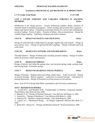
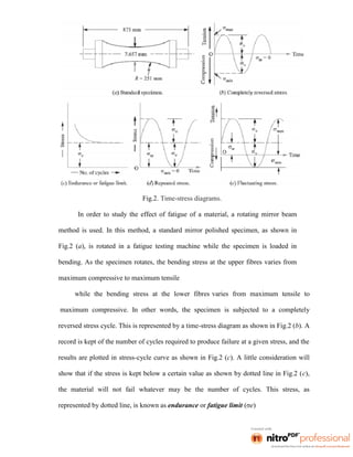
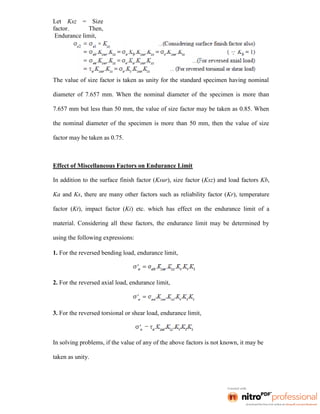
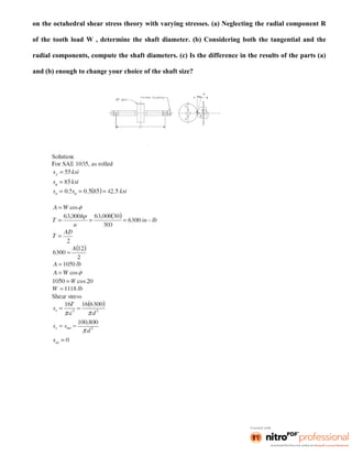
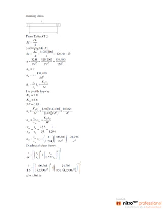
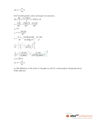
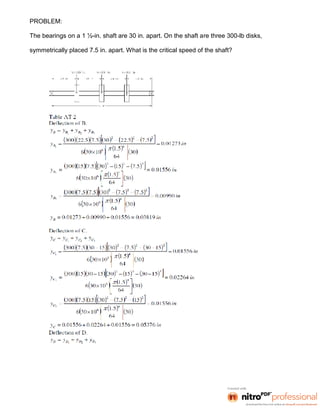
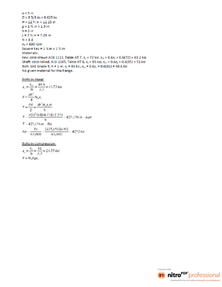
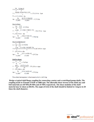
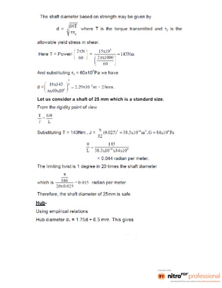
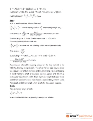
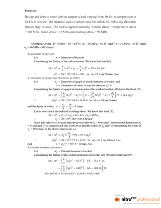
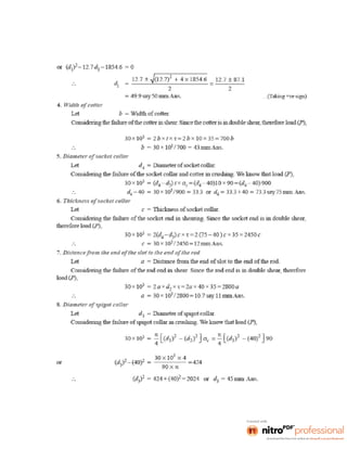
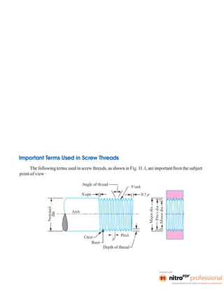
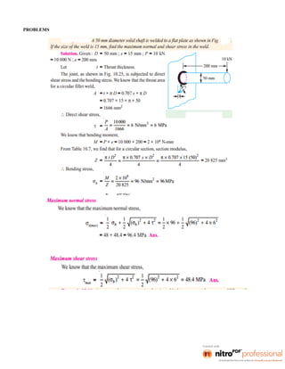
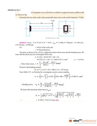
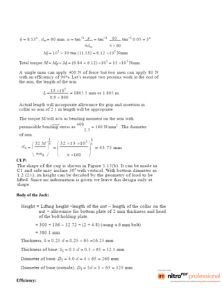
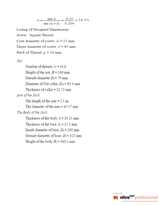
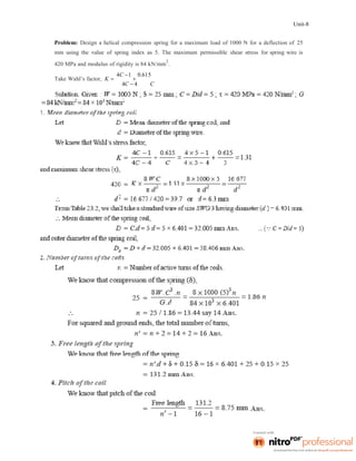
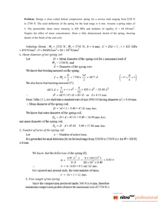
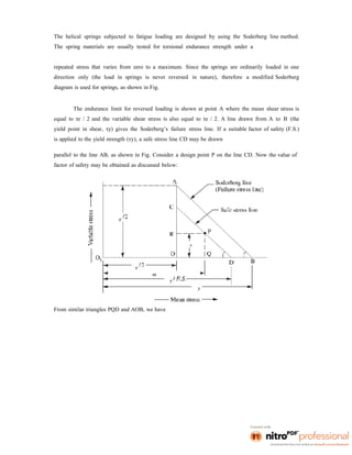
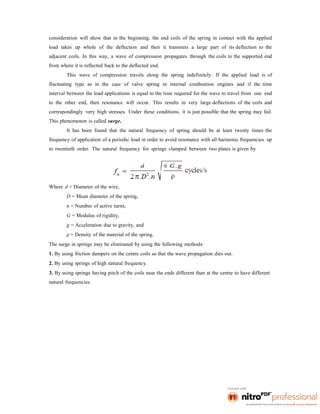
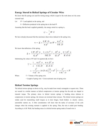
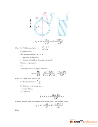
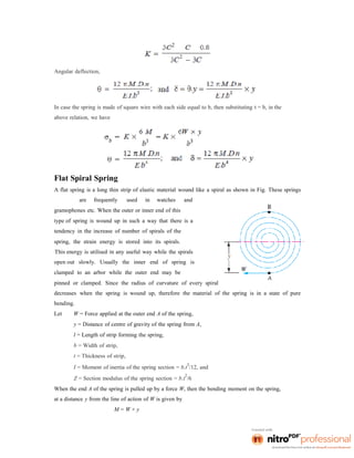
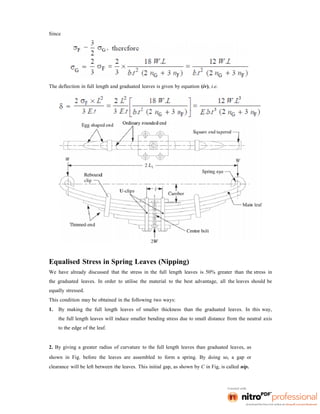
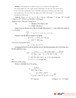
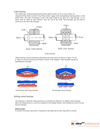
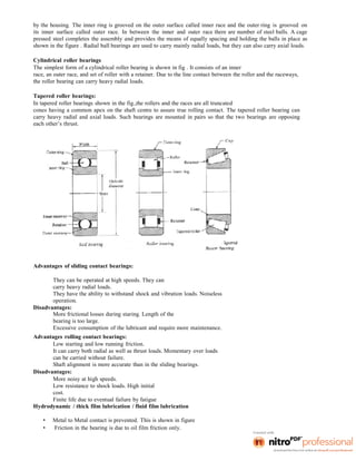
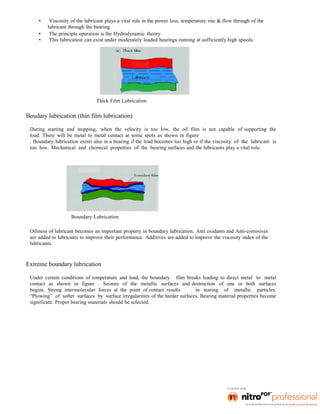
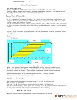
This document provides an overview of the course Design of Machine Elements. It discusses key considerations in machine design like the design process, classifications of designs, factors influencing design like material selection and stresses, and general design principles. The course covers topics like design of shafts and couplings, fasteners, springs, bearings and flywheels. It aims to impart knowledge of engineering mechanics, strength of materials and other topics to successfully design machine components.

![material at some given rate or the energy required to remove a unit volume of the material.
It may be noted that brass can be easily machined than steel.
10. Resilience:
It is the property of a material to absorb energy and to resist shock and impact loads. It is
measured by the amount of energy absorbed per unit volume within elastic limit. This
property is essential for spring materials.
11. Creep:
When a part is subjected to a constant stress at high temperature for a long period of time,
it will undergo a slow and permanent deformation called creep. This property is considered
in designing internal combustion engines, boilers and turbines.
12. Fatigue:
When a material is subjected to repeated stresses, it fails at stresses below the yield point
stresses. Such type of failure of a material is known as *fatigue. The failure is caused by
means of a progressive crack formation which are usually fine and of microscopic size.
This property is considered in designing shafts, connecting rods, springs, gears, etc.
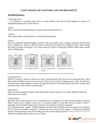
13. Hardness:
It is a very important property of the metals and has a wide variety of meanings. It
embraces many different properties such as resistance to wear, scratching, deformation and
machinability etc. It also means the ability of a metal to cut another metal. The hardness is
usually expressed in numbers which are dependent on the method of making the test. The
hardness of a metal may be determined by the following tests:
(a) Brinell hardness test,
(b) Rockwell hardness test,
(c) Vickers hardness (also called Diamond Pyramid) test, and
(d) Shore scleroscope.
The plain carbon steels varying from 0.06% carbon to 1.5% carbon are divided into the
following types depending upon the carbon content.
1. Dead mild steel — up to 0.15% carbon
2. Low carbon or mild steel — 0.15% to 0.45% carbon
3. Medium carbon steel — 0.45% to 0.8% carbon
4. High carbon steel — 0.8% to 1.5% carbon
According to Indian standard *[IS: 1762 (Part-I)–1974], a new system of designating
the steel is recommended. According to this standard, steels are designated on the](https://image.slidesharecdn.com/dmenotes-240313043627-e3c612c6/85/DESIGN-OF-MACHINE-ELEMENTS-NOTES-PDF-SHARE-11-320.jpg)


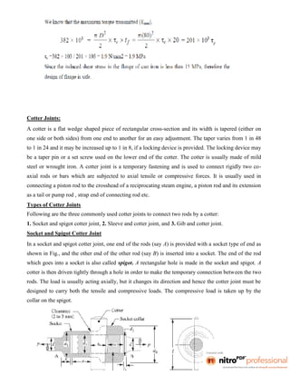

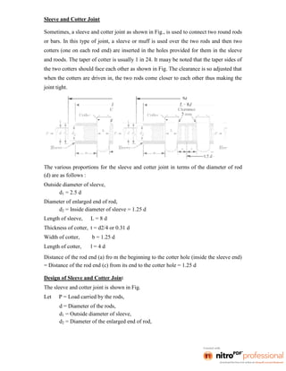
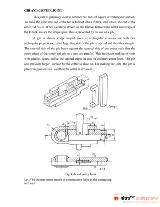
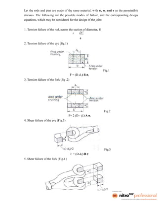
![Fig.3
The thickness, t2 may be taken as (1.15 to 1.5) t], and
Thickness of the cotter, t = b/4.
5. Crushing between the rod and cotter (Fig.1)
F = h t σc ; and h = 2t3
6. Crushing between the strap and gib(Fig.3)
F = 2 t t3 σc
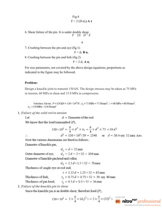
7. Shear failure of the rod end. It is under double shear (Fig.4).
Fig.4
F = 2l1hτ
8. Shear failure of the strap end. It is under double shear (Fig.5).
Fig.5
F = 4 l2 t3τ
9. Shear failure of the cotter and gib. It is under double shear.
F=2Btτ
The following proportions for the widths of the cotter and gib may be followed:](https://image.slidesharecdn.com/dmenotes-240313043627-e3c612c6/85/DESIGN-OF-MACHINE-ELEMENTS-NOTES-PDF-SHARE-93-320.jpg)


![Chapter1 [Autosaved].ppt](https://cdn.slidesharecdn.com/ss_thumbnails/chapter1autosaved-220812110755-514ab5ec-thumbnail.jpg?width=640&height=640&fit=bounds)