Downloaded 86 times

![1
QUESTIONS
QN 1 Find out the numbers of the R5 basic series from 1 to 10.
QN 2
Find out the numbers of R20/4(100, …, 1000) derived series.
QN 3
A manufacturer is interested in starting a business with five different models of tractors ranging
from 7.5 to 75 kW capacities. Specify power capacities of the models. There is an expansion
plan to further increase the number of models from fi ve to nine to fulfill the requirement of
farmers. Specify the power capacities of the additional models.
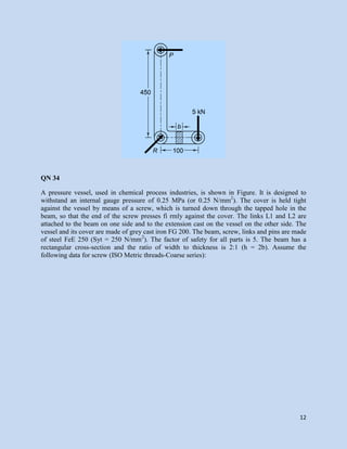
QN 4
It is required to standardize eleven shafts from 100 to 1000 mm diameter. Specify their
diameters.
QN 5
5.1 Define machine design.
5.2 What is the fi nal outcome of a machine Design process?
5.3 Name the various requirements of a product giving suitable example.
5.4 What are the basic requirements of a machine element?
5.5 What are the steps involved in design of a machine element?
5.6 Defi ne design synthesis.
5.7 Distinguish between design synthesis and design analysis.
5.8 What is standardization?
5.9 What are the three basic types of standards used in a design offi ce?
5.10 What do you understand by size of a product? Give examples.
5.11 What are preferred numbers?
5.12 How many basic series are used? How will you denote them?
5.13 What is a derived series?
5.14 How will you form a derived series?
5.15 What is industrial design?
5.16 Define ergonomics.
5.17 Explain man–machine joint system.
5.18 What is concurrent engineering?
QN 6
Find out the numbers of R10 basic series from 1 to 10.
QN 7
Find out the numbers of R20/3 (200,…) derived series. [200, 280(282.5), 400(399.03),
560(563.63),800(796.13), 1120(1124.53), …] (f = 1.4125)](https://image.slidesharecdn.com/supplementaryquestionseasyeng-180302223528/85/MACHINE-DESIGN-QUESTION-BANK-3-320.jpg)

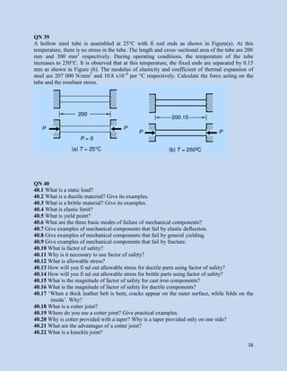
QN 9
It is required to standardize 11 speeds from 72 to 720 rpm for a machine tool. Specify the speeds.
[72, 90.64, 114.11, 143.65, 180.84, 227.66, 286.60, 360.80, 454.22, 571.81, 719.85 rpmi]
QN 9
It is required to select a material by the weighted point method. There are four Candidate
materials, viz., low alloy steel, plain carbon steel, stainless steel and chromium steel, Which have
passed through screening test. For a particular application, the designer has given a 5-point
weightage for ultimate tensile strength, 3-point weightage for hardenability and 2-point
Weightage for cost-economy. Table below gives the data for the candidate materials.
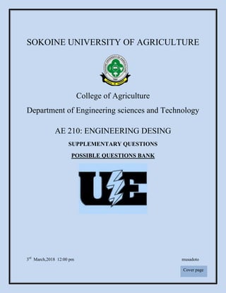
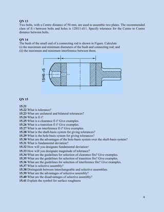
QN 10
The main bearing of an engine is shown in Figure. Calculate
(i) the maximum and minimum diameters of the bush and crank pin; and
(ii) the maximum and minimum clearances between the crank pin and bush. Suggest suitable
machining methods for both](https://image.slidesharecdn.com/supplementaryquestionseasyeng-180302223528/85/MACHINE-DESIGN-QUESTION-BANK-4-320.jpg)
![17
40.23 Where do you use a knuckle joint? Give practical examples.
40.24 What are the advantages of a knuckle joint?
40.25 What is advantage of using the theories of elastic failures?
40.26 What are the important theories of elastic failures?
40.27 State maximum principal stress theory of failure.
40.28 Where do you use maximum principal stress theory of failure?
40.29 State maximum shear stress theory of failure.
40.30 Where do you use maximum shear stress theory of failure?
40.31 State distortion energy theory of failure
40.32 Where do you use distortion energy theory of failure?
40.33 What is fracture mechanics?
40.34 What is stress intensity factor in fracture mechanics?
40.35 What is fracture toughness in fracture mechanics?
40.36 What is a curved beam? Give practical examples of machine components made of curved
beams.
40.37 Distinguish stress distribution in curved and straight beams.
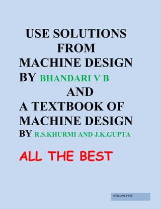
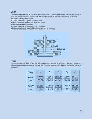
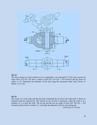
QN 41
Two rods are connected by means of a knuckle joint as shown in Figure. The axial force P acting
on the rods is 25 kN. The rods and the pin are made of plain carbon steel 45C8 (Syt = 380
N/mm2
) and the factor of safety is 2.5. The yield strength in shear is 57.7% of the yield strength
in tension. Calculate: (i) the diameter of the rods, and (ii) the diameter of the pin.
[(i) 14.47 mm (ii) 13.47 mm]](https://image.slidesharecdn.com/supplementaryquestionseasyeng-180302223528/85/MACHINE-DESIGN-QUESTION-BANK-19-320.jpg)
![19
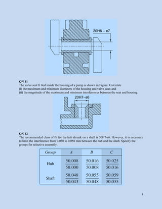
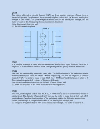
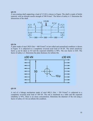
QN 44
A C-frame subjected to a force of 15 kN is shown in Figure. It is made of grey cast iron FG 300
and the factor of safety is 2.5 Determine the dimensions of the crosssection of the frame.
(t = 15.81 mm)
QN 45
The principal stresses induced at a point in a machine component made of steel 50C4
(Syt = 460 N/mm2
) are as follows:s1= 200N/mm2
s2 = 150 N/mm2 s3 = 0 Calculate the factor of
safety by (i) the maximum shear stress theory, and (ii) the distortion energy theory.
[(i) 2.3 (ii) 2.55]
QN 46 The stresses induced at a critical point in a machine component made of steel 45C8
(Syt= 380 N/mm2
) are as follows: sx = 100 N/mm2 s y = 40 N/mm2 txy = 80 N/mm2
Calculate the
factor of safety by (i) the maximum normal stress theory, (ii) the maximum shear stress theory,
and (iii) the distortion energy theory. [(i) 2.44 (ii) 2.22 (iii) 2.32]](https://image.slidesharecdn.com/supplementaryquestionseasyeng-180302223528/85/MACHINE-DESIGN-QUESTION-BANK-21-320.jpg)
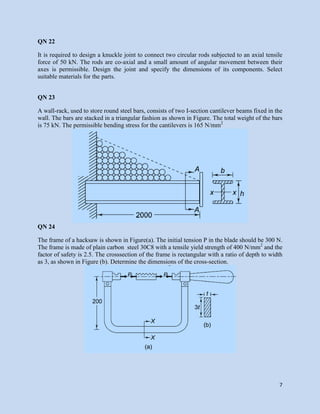
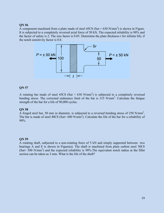
![20
QN 47 A link of S-shape made of a round steel bar is shown in Figure. It is made of plain carbon
steel 45C8 (Syt = 380 N/mm2) and the factor of safety is 4.5. Calculate the dimensions of the
link. (d = 23.38 mm)
QN 48
The frame of a 100 kN capacity press is shown in Figure. It is made of grey cast iron FG 300 and
the factor of safety is 2.5. Determine the dimensions of the crosssection at XX.
(t = 26.62 mm)
QN 49
A bell crank lever is subjected to a force of 7.5 kN at the short arm end. The lengths of the short
and long arms are 100 and 500 mm respectively. The arms are at right angles to each other. The
lever and the pins are made of steel FeE 300 (Syt = 300 N/mm2
) and the factor of safety is 5. The
permissible bearing pressure on the pin is 10 N/mm2. The lever has a rectangular cross section
and the ratio of width to thickness is 4 : 1.The length to diameter ratio of the fulcrum pin is
1.5 : 1. Calculate:
(i) the diameter and the length of the fulcrum pin
(ii) the shear stress in the pin
(iii) the dimensions of the boss of the lever at the fulcrum pin
(iv) the dimensions of the cross-section of the lever Assume that the arm of the bending moment
on the lever extends up to the axis of the fulcrum.
[(i) 22.58 and 33.87 mm (ii) 9.55 N/mm2
(iii) Di = 23 mm D0 = 46 mm
length = 34 mm, (iv) 16.74 x 66.94 mm]](https://image.slidesharecdn.com/supplementaryquestionseasyeng-180302223528/85/MACHINE-DESIGN-QUESTION-BANK-22-320.jpg)
![21
QN 50
A bracket, made of steel FeE 200 (Syt = 200N/mm2) and subjected to a force of 5 Kn at an
angle of 30° to the vertical, is shown in Fig. 4.75. The factor of safety is 4. Determine the
dimensions of the crosssection of the bracket. [t = 33.5 mm]
QN 51
Figure below shows a C-clamp, which carries a load P of 25 kN. The cross-section of the clamp
is rectangular and the ratio of width to thickness (b/t) is 2 : 1. The clamp is made of cast steel of
Grade 20-40 (Sut = 400 N/mm2
) and the factor of safety is 4. Determine the dimensions of the
cross-section of the clamp. [t = 38.5 mm]
QN 52
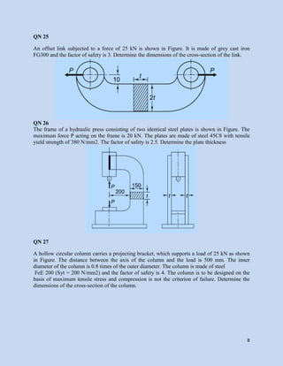
A flat plate subjected to a tensile force of 5 kN is shown in Figure. The plate material is grey cast
iron FG 200 and the factor of safety is 2.5. Determine the thickness of the plate.](https://image.slidesharecdn.com/supplementaryquestionseasyeng-180302223528/85/MACHINE-DESIGN-QUESTION-BANK-23-320.jpg)
![27
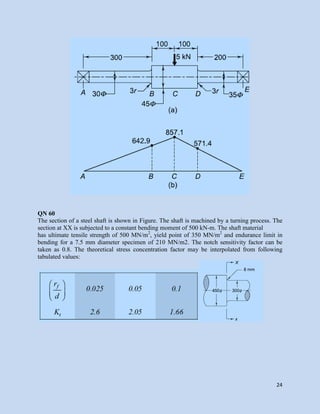
QN 69
A machine component is subjected to two-dimensional stresses. The tensile stress in the X
direction varies from 40 to 100 N/mm2
while the tensile stress in the Y direction varies from 10
to 80 N/mm2
. The frequency of variation of these stresses is equal. The corrected endurance limit
of the component is 270 N/mm2
. The ultimate tensile strength of the material of the component is
660 N/mm2. Determine the factor of safety used by the designer.
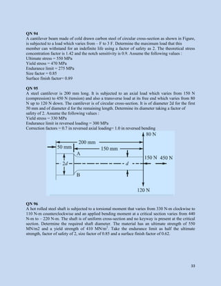
QN 70
A transmission shaft carries a pulley midway between the two bearings. The bending moment at
the pulley varies from 200 N-m to 600 N-m, as the torsional moment in the shaft varies from 70
N-m to 200 N-m. The frequencies of variation of bending and torsional moments are equal to the
shaft speed. The shaft is made of steel FeE 400 (Sut = 540 N/mm2
and Syt = 400 N/mm2
). The
corrected endurance limit of the shaft is 200 N/mm2. Determine the diameter of the shaft using a
factor of safety of 2.
QN 71
A mass of 50 kg drops through 25 mm at the centre of a 250 mm long simply supported beam.
The beam has a square cross-section. It is made of steel 30C8 (Syt = 400 N/mm2
) and the factor
of safety is 2. The modulus of elasticity is 207 000 N/mm2. Determine the dimension of the
cross section of the beam.
QN 72+
A rectangular plate, 15 mm thick, made of a brittle material is shown in Figure. Calculate the
stresses at each of three holes of 3, 5 and 10 mm diameter.[161.82, 167.33 and 200 N/mm2
]](https://image.slidesharecdn.com/supplementaryquestionseasyeng-180302223528/85/MACHINE-DESIGN-QUESTION-BANK-29-320.jpg)
![28
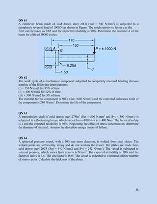
QN 73
A round shaft made of a brittle material and subjected to a bending moment of 15 N-m is shown
in Figure. The stress concentration factor at the fillet is 1.5 and the ultimate tensile strength of
the shaft material is 200 N/mm2
.Determine the diameter d, the magnitude of stress at the fillet
and the factor of safety. [11.76 mm, 140.91 N/mm2, and 1.42]
QN 74
A shaft carrying a load of 5 kN midway between two bearings is shown in Figure. Determine the
maximum bending stress at the fi llet section. Assume the shaft material to be brittle.
[20.39 N/mm2]
QN 75
A plate, 10 mm thick, subjected to a tensile load of 20 kN is shown in Figure. The plate is made
of cast iron (Sut = 350 N/mm2
) and the factor of safety is 2.5. Determine the fillet radius.
[2.85 or 3 mm]](https://image.slidesharecdn.com/supplementaryquestionseasyeng-180302223528/85/MACHINE-DESIGN-QUESTION-BANK-30-320.jpg)
![29
QN 76
A 25 mm diameter shaft is made of forged steel 30C8 (Sut = 600 N/mm2
). There is a step in the
shaft and the theoretical stress concentration factor at the step is 2.1. The notch sensitivity factor
is 0.84. Determine the endurance limit of the shaft if it is subjected to a reversed bending
moment. [59.67 N/mm2]
QN 78
A 40 mm diameter shaft is made of steel 50C4 (Sut = 660 N/mm2
) and has a machined surface.
The expected reliability is 99%. The theoretical stress concentration factor for the shape of the
shaft is 1.6 and the notch sensitivity factor is 0.9. Determine the endurance limit of the shaft.
[112.62 N/mm2]
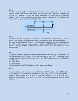
QN 79
A cantilever beam made of steel Fe 540 (Sut = 540 N/mm2
and Syt = 320 N/mm2
) and subjected
to a completely reversed load (P) of 5 kN is shown in Figure. The beam is machined and the
reliability is 50%. The factor of safety is 2 and the notch sensitivity factor is 0.9. Calculate
(i) endurance limit at the fi llet section; and
(ii) diameter d of the beam for infinite life. [(i) 109.20 N/mm2 (ii) 45.35 mm]
QN 80
A solid circular shaft made of steel Fe 620 (Sut = 620 N/mm2
and Syt = 380 N/mm2
) is subjected
to an alternating torsional moment, which varies from –200 N-m to + 400 N-m. The shaft is
ground and the expected reliability is 90%. Neglecting stress concentration, calculate the shaft
diameter for infinite life. The factor of safety is 2. Use the distortion energy theory of failure.
[29.31 mm]
QN 81
A solid circular shaft, 15 mm in diameter, is subjected to torsional shear stress, which varies
from 0 to 35 N/mm2 and at the same time, is subjected to an axial stress that varies from –15 to
+30 N/mm2
. The frequency of variation of these stresses is equal to the shaftspeed. The shaft is
made of steel FeE 400 (Sut = 540 N/mm2 and Syt = 400 N/mm2
) and the corrected endurance
limit of the shaft is 200 N/mm2
. Deter mine the factor of safety. [4.05]
QN 82
A bar of steel has an ultimate tensile strength of 700 MPa, a yield point stress of 400 MPa and
fully corrected endurance limit (Se) of 220 MPa. The bar is subjected to a mean bending stress of
60 MPa and a stress amplitude of 80 MPa. Superimposed on it is a mean torsional stress and
torsional stress amplitude of 70 and 35 MPa respectively. Find the factor of safety. [1.54]QN 83
Flat plate for an agricultural implement is subjected to a tensile force of 5 kN as shown in figure.
The plate material is grey cast iron GG 20 and the factor of safety is considered to be 2.5.
Determine the thickness of the plate.](https://image.slidesharecdn.com/supplementaryquestionseasyeng-180302223528/85/MACHINE-DESIGN-QUESTION-BANK-31-320.jpg)
![30
QN 84
A rotating beam of combine harvester made of steel, σult = 630 N/mm2
is subjected to a
completely reversed bending stress. Calculate the endurance strength of the beam for a life of
90,000 cycles. [Finite-life problem with reversed load]
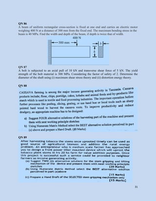
QN 85
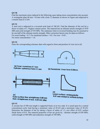
Figure below shows a production of a machine part. Explaining the geometrical tolerance
symbols shown in a drawing.](https://image.slidesharecdn.com/supplementaryquestionseasyeng-180302223528/85/MACHINE-DESIGN-QUESTION-BANK-32-320.jpg)

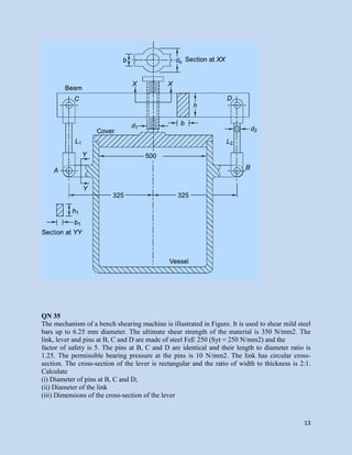
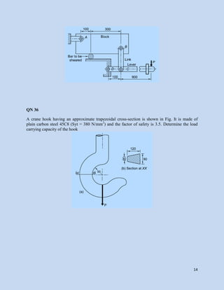
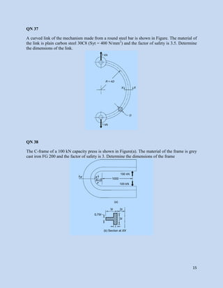
The document contains 38 questions related to machine design. The questions cover topics such as standardization of sizes, tolerances, fits, design of joints, shafts, levers, frames and other machine elements. Design calculations are required to determine dimensions that satisfy given loading and stress criteria. Materials, their properties and appropriate factors of safety are provided. References for solutions and examples are given from standard machine design textbooks.


![3 1 ii mid dme questions & bits [pls vist our blog sres11jemeches]](https://cdn.slidesharecdn.com/ss_thumbnails/3-1iimiddmequestionsbitsplsvistourblogsres11jemeches-131214095432-phpapp02-thumbnail.jpg?width=640&height=640&fit=bounds)


![CONSTRUCTION [soil treatment, foundation backfill, Damp Proof Membrane[DPM] a...](https://cdn.slidesharecdn.com/ss_thumbnails/kahimba-181220112907-thumbnail.jpg?width=640&height=640&fit=bounds)