Downloaded 102 times

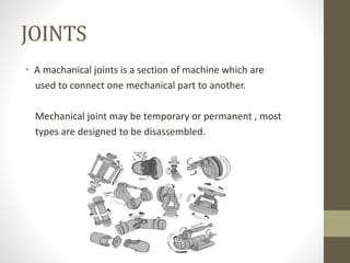
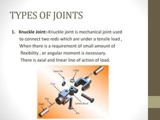

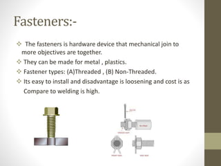


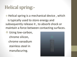


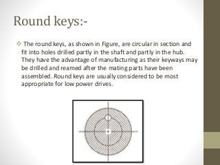
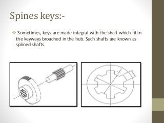


This document provides an overview of machine design topics including joints, fasteners, springs, and bearings. It discusses common joint types like knuckle and cotter joints. For springs, it covers material selection criteria and types like helical and leaf springs. Bearing types include ball, roller, hydrodynamic, and hydrostatic with descriptions of functions and examples. The document also examines design of keys including sunk, saddle, tangent, round, and splined varieties.