Downloaded 648 times

![System Architecture Description
To minimize network complexity, the currently termination point in the network for ciphering/in-
agreed LTE architecture is as shown in Figure 1 [2, tegrity protection for NAS signaling and handles
3]. the security key management. Lawful interception
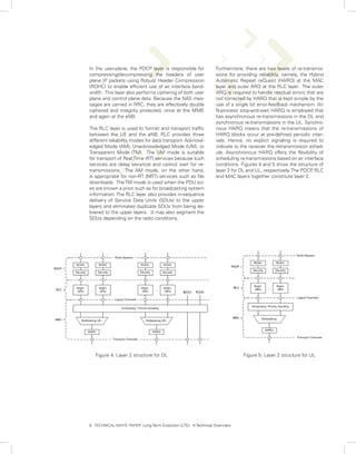
of signaling is also supported by the MME. The
Functional Elements MME also provides the control plane function for
The architecture consists of the following functional mobility between LTE and 2G/3G access networks
elements: with the S3 interface terminating at the MME from
the SGSN. The MME also terminates the S6a inter-
Evolved Radio Access Network (RAN) face towards the home HSS for roaming UEs.
The evolved RAN for LTE consists of a single node,
i.e., the eNodeB (eNB) that interfaces with the UE. Packet Data Network Gateway (PDN GW)
The eNB hosts the PHYsical (PHY), Medium Access The PDN GW provides connectivity to the UE to
Control (MAC), Radio Link Control (RLC), and Pack- external packet data networks by being the point of
et Data Control Protocol (PDCP) layers that include exit and entry of traffic for the UE. A UE may have
the functionality of user-plane header-compression simultaneous connectivity with more than one
and encryption. It also offers Radio Resource Con- PDN GW for accessing multiple PDNs. The PDN
trol (RRC) functionality corresponding to the control GW performs policy enforcement, packet filtering
plane. It performs many functions including radio for each user, charging support, lawful Interception
resource management, admission control, sched- and packet screening. Another key role of the PDN
uling, enforcement of negotiated UL QoS, cell in- GW is to act as the anchor for mobility between
formation broadcast, ciphering/deciphering of user 3GPP and non-3GPP technologies such as WiMAX
and control plane data, and compression/decom- and 3GPP2 (CDMA 1X and EvDO).
pression of DL/UL user plane packet headers.
Key Features
Serving Gateway (SGW)
The SGW routes and forwards user data packets, EPS to EPC
while also acting as the mobility anchor for the user A key feature of the EPS is the separation of the
plane during inter-eNB handovers and as the anchor network entity that performs control-plane func-
for mobility between LTE and other 3GPP technolo- tionality (MME) from the network entity that per-
gies (terminating S4 interface and relaying the traf- forms bearer-plane functionality (SGW) with a well
fic between 2G/3G systems and PDN GW). For idle defined open interface between them (S11). Since
state UEs, the SGW terminates the DL data path E-UTRAN will provide higher bandwidths to en-
and triggers paging when DL data arrives for the able new services as well as to improve existing
UE. It manages and stores UE contexts, e.g. pa- ones, separation of MME from SGW implies that
rameters of the IP bearer service, network internal SGW can be based on a platform optimized for high
routing information. It also performs replication of bandwidth packet processing, where as the MME
the user traffic in case of lawful interception. is based on a platform optimized for signaling trans-
actions. This enables selection of more cost-effec-
Mobility Management Entity (MME) tive platforms for, as well as independent scaling
The MME is the key control-node for the LTE ac- of, each of these two elements. Service providers
cess-network. It is responsible for idle mode UE can also choose optimized topological locations of
tracking and paging procedure including retransmis- SGWs within the network independent of the lo-
sions. It is involved in the bearer activation/deactiva- cations of MMEs in order to optimize bandwidth
tion process and is also responsible for choosing reduce latencies and avoid concentrated points of
the SGW for a UE at the initial attach and at time failure.
of intra-LTE handover involving Core Network (CN)
node relocation. It is responsible for authenticating S1-flex Mechanism
the user (by interacting with the HSS). The Non- The S1-flex concept provides support for network
Access Stratum (NAS) signaling terminates at the redundancy and load sharing of traffic across net-
MME and it is also responsible for generation and work elements in the CN, the MME and the SGW,
allocation of temporary identities to UEs. It checks by creating pools of MMEs and SGWs and allowing
the authorization of the UE to camp on the service each eNB to be connected to multiple MMEs and
provider’s Public Land Mobile Network (PLMN) and SGWs in a pool.
enforces UE roaming restrictions. The MME is the
4. TECHNICAL WHITE PAPER: Long Term Evolution (LTE): A Technical Overview](https://image.slidesharecdn.com/ltetechnicaloverview-100112093607-phpapp02/85/LTE-Technical-Overview-4-320.jpg)
![Network Sharing
The LTE architecture enables service providers to reduce the cost of owning and operating the network by al-
lowing the service providers to have separate CN (MME, SGW, PDN GW) while the E-UTRAN (eNBs) is jointly
shared by them. This is enabled by the S1-flex mechanism by enabling each eNB to be connected to multiple
CN entities. When a UE attaches to the network, it is connected to the appropriate CN entities based on the
identity of the service provider sent by the UE.
(Untrusted non-3GPP access requires ePDG in the data path)
Figure 1: High level architecture for 3GPP LTE (Details of all LTE interfaces are given in Appendix A)
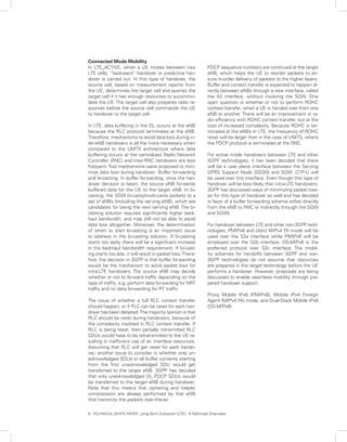
PROTOCOL LAYER ARCHITECTURE
In this section, we describe the functions of the different protocol
layers and their location in the LTE architecture. Figures 2 and 3
show the control plane and the user plane protocol stacks, respec-
tively [4]. In the control-plane, the NAS protocol, which runs between
the MME and the UE, is used for control-purposes such as network
attach, authentication, setting up of bearers, and mobility manage-
ment. All NAS messages are ciphered and integrity protected by the
MME and UE. The RRC layer in the eNB makes handover decisions
based on neighbor cell measurements sent by the UE, pages for
Figure 2: Control plane protocol stack the UEs over the air, broadcasts system information, controls UE
measurement reporting such as the periodicity of Channel Quality
Information (CQI) reports and allocates cell-level temporary identi-
fiers to active UEs. It also executes transfer of UE context from the
source eNB to the target eNB during handover, and does integrity
protection of RRC messages. The RRC layer is responsible for the
setting up and maintenance of radio bearers.
Figure 3: User plane protocol stack
5. TECHNICAL WHITE PAPER: Long Term Evolution (LTE): A Technical Overview](https://image.slidesharecdn.com/ltetechnicaloverview-100112093607-phpapp02/85/LTE-Technical-Overview-5-320.jpg)
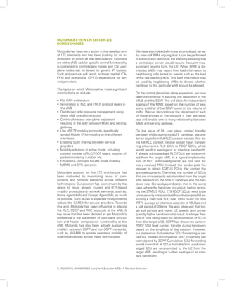
![Figure 6: Logical channels in LTE
Figure 7: Transport channels in LTE
In LTE, there is significant effort to simplify the number
and mappings of logical and transport channels. The dif-
ferent logical and transport channels in LTE are illustrated
in Figures 6 and 7 respectively. The transport channels are
,
distinguished by the characteristics (e.g. adaptive modula-
tion and coding) with which the data are transmitted over
the radio interface. The MAC layer performs the mapping
between the logical channels and transport channels,
schedules the different UEs and their services in both UL
and DL depending on their relative priorities, and selects
the most appropriate transport format. The logical chan-
nels are characterized by the information carried by them.
The mapping of the logical channels to the transport chan-
nels is shown in Figure 8 [4]. The mappings shown in dot-
ted lines are still being studied by 3GPP.
Figure 8: Logical to transport channel mapping [4]
7 TECHNICAL WHITE PAPER: Long Term Evolution (LTE): A Technical Overview
.](https://image.slidesharecdn.com/ltetechnicaloverview-100112093607-phpapp02/85/LTE-Technical-Overview-7-320.jpg)
![The physical layer at the eNB is responsible for pro- ing areas were used in earlier technologies, such
tecting data against channel errors using adaptive as, GSM. However, there are newer techniques that
modulation and coding (AMC) schemes based on avoid ping-pong effects, distribute the TA update load
channel conditions. It also maintains frequency and more evenly across cells and reduce the aggregate TA
time synchronization and performs RF processing in- update load. Some of the candidate mechanisms that
cluding modulation and demodulation. In addition, it were discussed include overlapping TAs, multiple TAs
processes measurement reports from the UE such and distance-based TA schemes. It has been agreed
as CQI and provides indications to the upper layers. in 3GPP that a UE can be assigned multiple TAs that
The minimum unit of scheduling is a time-frequency are assumed to be non-overlapping. It has also been
block corresponding to one sub-frame (1ms) and 12 agreed in 3GPP that TAs for LTE and for pre-LTE RATs
sub-carriers. The scheduling is not done at a sub-car- will be separate i.e., an eNB and a UMTS Node-B will
rier granularity in order to limit the control signaling. belong to separate TAs to simplify the network’s han-
QPSK, 16QAM and 64QAM will be the DL and UL dling of mobility of the UE when UE crosses 3GPP
modulation schemes in E-UTRA. For UL, 64-QAM is RAT boundaries.
optional at the UE.
Service Providers are likely to deploy LTE in a phased
Multiple antennas at the UE are supported with the manner and pre-existing 3GPP technologies, such as,
2 receive and 1 transmit antenna configuration being HSDPA, UMTS, EDGE and GPRS, are likely to remain
mandatory. MIMO (multiple input multiple output) for some time to come.
is also supported at the eNB with two transmit an-
tennas being the baseline configuration. Orthogonal
Frequency Division Multiple Access (OFDMA) with a
sub-carrier spacing of 15 kHz and Single Carrier Fre-
quency Division Multiple Access (SC-FDMA) have
been chosen as the transmission schemes for the
DL and UL, respectively. Each radio frame is 10ms
long containing 10 sub-frames with each sub-frame
capable of carrying 14 OFDM symbols. For more de-
tails on these access schemes, refer to [4].
MOBILITY MANAGEMENT
Mobility management can be classified based on the Figure 9: Mobility states of the UE in LTE.
radio technologies of the source and the target cells,
and the mobility-state of the UE. From a mobility per- There will be seams across between these tech-
spective, the UE can be in one of three states, LTE_ nologies and 3GPP has devised ways to minimize
DETACHED, LTE_IDLE, and LTE_ACTIVE as shown the network signaling when a UE, capable of trans-
in Figure 7 LTE_DETACHED state is typically a transi-
. mitting/receiving in multiple RATs, moves across
tory state in which the UE is powered-on but is in the these technology boundaries in idle mode. The ob-
process of searching and registering with the net- jective is to keep the UE camped in the idle state
work. In the LTE_ACTIVE state, the UE is registered of the different technologies, for e.g., LTE_IDLE in
with the network and has an RRC connection with LTE and PMM_IDLE in UMTS/GPRS and also not
the eNB. In LTE_ACTIVE state, the network knows to perform TA updates (LTE) or Routing Area (RA)
the cell to which the UE belongs and can transmit/ updates (UTRAN/GERAN) as the UE moves be-
receive data from the UE. The LTE_IDLE state is a tween these technologies. To achieve this, the UE
power-conservation state for the UE, where typically is assigned to both a TA and a RA. From then on,
the UE is not transmitting or receiving packets. In as long as the UE is moving among cells (possi-
LTE_IDLE state, no context about the UE is stored in bly of different 3GPP technologies) that broadcast
the eNB. In this state, the location of the UE is only one of these equivalent TA or RA identities, the UE
known at the MME and only at the granularity of a does not send a TA or RA update. When new traf-
tracking area (TA) that consists of multiple eNBs. The fic arrives for the UE, the UE is paged in both the
MME knows the TA in which the UE last registered technologies and depending on the technology in
and paging is necessary to locate the UE to a cell. which the UE responds, data is forwarded through
that RAT.
Idle Mode Mobility
In idle mode, the UE is in power-conservation Such a tight co-ordination of being able to page in
mode and does not inform the network of each cell multiple technologies at the same time will not be
change. The network knows the location of the UE possible with other RATs standardized by other
to the granularity of a few cells, called the Tracking standards bodies, such as, 3GPP2 and IEEE. There-
Area (TA). When there is a UE-terminated call, the fore, mobility between LTE and a non-3GPP tech-
UE is paged in its last reported TA. Extensive dis- nology would involve signaling the network of the
cussions occurred in 3GPP on the preferred track- technology change.
ing area mechanism. Static non-overlapping track-
8. TECHNICAL WHITE PAPER: Long Term Evolution (LTE): A Technical Overview](https://image.slidesharecdn.com/ltetechnicaloverview-100112093607-phpapp02/85/LTE-Technical-Overview-8-320.jpg)
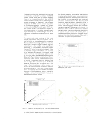
![EVOLVED MULTICAST BROADCAST MULTIME-
DIA SERVICES (E-MBMS)
There will be support for MBMS right from the first Both single-cell MBMS and MBSFN will typically use
version of LTE specifications. However, specifica- point-to-multipoint mode of transmission. Therefore,
tions for E-MBMS are in early stages. Two impor- UE feedback, such as, ACK/NACK and CQI cannot
tant scenarios have been identified for E-MBMS: be used as one could for the point-to-point case.
One is single-cell broadcast, and the second is However, aggregate statistical CQI and ACK/NACK
MBMS Single Frequency Network (MBSFN). information can still be used for link adaptation and
MBSFN is a new feature that is being introduced retransmissions. Such techniques are currently be-
in the LTE specification. MBSFN is envisaged for ing evaluated in 3GPP .
delivering services such as Mobile TV using the LTE
infrastructure, and is expected to be a competitor
to DVB-H-based TV broadcast. In MBSFN, the trans-
mission happens from a time-synchronized set of
eNBs using the same resource block. This enables
over-the-air combining, thus improving the Signal-
to-Interference plus Noise-Ratio (SINR) significantly
compared to non-SFN operation. The Cyclic Prefix
(CP) used for MBSFN is slightly longer, and this
enables the UE to combine transmissions from
different eNBs, thus somewhat negating some of
the advantages of SFN operation. There will be six
symbols in a slot of 0.5ms for MBSFN operation
versus seven symbols in a slot of 0.5ms for non-
SFN operation.
The overall user-plane architecture for MBSFN op-
eration is shown in Figure 10. 3GPP has defined
a SYNC protocol between the E-MBMS gateway
and the eNBs to ensure that the same content is
sent over-the-air from all the eNBs. As shown in
the figure, eBM-SC is the source of the MBMS
traffic, and the E-MBMS gateway is responsible for
distributing the traffic to the different eNBs of the
MBSFN area. IP multicast may be used for distrib-
uting the traffic from the E-MBMS gateway to the
different eNBs. 3GPP has defined a control plane
entity, known as the MBMS Coordination Entity
(MCE) that ensures that the same resource block
is allocated for a given service across all the eNBs
of a given MBSFN area. It is the task of the MCE
to ensure that the RLC/MAC layers at the eNBs
are appropriately configured for MBSFN operation.
3GPP has currently assumed that header compres- Figure 10: The overall U-plane architecture of the
sion for MBMS services will be performed by the MBMS content synchronization [4]
E-MBMS gateway.
10. TECHNICAL WHITE PAPER: Long Term Evolution (LTE): A Technical Overview](https://image.slidesharecdn.com/ltetechnicaloverview-100112093607-phpapp02/85/LTE-Technical-Overview-10-320.jpg)
![CONCLUSIONS
In this paper, we described the system architecture and performance objectives
of the next generation access-network technology being developed by 3GPP .
We also discussed how mobility is handled in the new system. Motorola’s role
in this enhancement of 3GPP LTE technology was also explained.
With the envisaged throughput and latency targets and emphasis on simplicity,
spectrum flexibility, added capacity and lower cost per bit, LTE is destined to
provide greatly improved user experience, delivery of new revenue generating
exciting mobile services and will remain a strong competitor to other wireless
technologies in the next decade for both developed and emerging markets.
Motorola is leveraging its extensive expertise in mobile broadband innovation,
including OFDM technologies (wi4 WiMAX), cellular networking (EVDOrA,
HSxPA), IMS ecosystem, collapsed IP architecture, standards development and
implementation, comprehensive services to deliver best-in-class LTE solutions.
For more information on LTE, please talk to your Motorola representative.
REFERENCES
[1]. 3GPP TR 25.913. Requirements for Evolved UTRA (E-UTRA) and Evolved
UTRAN (E-UTRAN). Available at http://www.3gpp.org.
[2]. 3GPP TS 23.401. GPRS enhancements on EUTRAN access. Available at
http://www.3gpp.org.
[3]. 3GPP TS 23.402. Architecture enhancements for non-3GPP accesses. Avail-
able at http://
www.3gpp.org.
[4]. 3GPP TS 36.300, EUTRA and EUTRAN overall description, Stage 2. Available
at http://www.3gpp.org
[5]. C. Perkins. IP Mobility Support for IPv4. RFC 3344, August 2002. Available at
http://www.ietf.org/rfc/rfc3344.txt?number=3344.
[6]. S. Gundavelli et. al. Proxy Mobile IPv6. IETF draft, April 2007 Available at
.
http://www.ietf.org/internet-drafts/drafts-ietf-netlmm-proxymip6-00.txt.
[7]. H. Soliman. Mobile IPv6 support for dual stack hosts and routers (DSMIPv6).
Available at http://tools.ietf.org/html/draft-ietf-mip6-nemo-v4traversal-04.
13 TECHNICAL WHITE PAPER: Long Term Evolution (LTE): A Technical Overview](https://image.slidesharecdn.com/ltetechnicaloverview-100112093607-phpapp02/85/LTE-Technical-Overview-13-320.jpg)
![Appendix A: LTE Reference Points
S1-MME Reference point for the control plane protocol between EUTRAN and
MME. The protocol over this reference point is eRANAP and it uses Stream Con-
trol Transmission Protocol (SCTP) as the transport protocol
S1-U Reference point between EUTRAN and SGW for the per-bearer user
plane tunneling and inter-eNB path switching during handover. The transport pro-
tocol over this interface is GPRS Tunneling Protocol-User plane (GTP-U)
S2a It provides the user plane with related control and mobility support be-
tween trusted non-3GPP IP access and the Gateway. S2a is based on Proxy Mo-
bile IP To enable access via trusted non-3GPP IP accesses that do not support
.
PMIP S2a also supports Client Mobile IPv4 FA mode
,
S2b It provides the user plane with related control and mobility support be-
tween evolved Packet Data Gateway (ePDG) and the PDN GW. It is based on
Proxy Mobile IP
S2c It provides the user plane with related control and mobility support be-
tween UE and the PDN GW. This reference point is implemented over trusted
and/or untrusted non-3GPP Access and/or 3GPP access. This protocol is based
on Client Mobile IP co-located mode
S3 It is the interface between SGSN and MME and it enables user and bearer
information exchange for inter 3GPP access network mobility in idle and/or ac-
tive state. It is based on Gn reference point as defined between SGSNs
S4 It provides the user plane with related control and mobility support between
SGSN and the SGW and is based on Gn reference point as defined between
SGSN and GGSN
S5 It provides user plane tunneling and tunnel management between SGW and
PDN GW. It is used for SGW relocation due to UE mobility and if the SGW needs
to connect to a non-collocated PDN GW for the required PDN connectivity. Two
variants of this interface are being standardized depending on the protocol used,
namely, GTP and the IETF based Proxy Mobile IP solution [3]
S6a It enables transfer of subscription and authentication data for authenti-
cating/authorizing user access to the evolved system (AAA interface) between
MME and HSS
S7 It provides transfer of (QoS) policy and charging rules from Policy and Charg-
ing Rules Function (PCRF) to Policy and Charging Enforcement Function (PCEF)
in the PDN GW. This interface is based on the Gx interface
S10 Reference point between MMEs for MME relocation and MME to MME
information transfer
S11 Reference point between MME and SGW
SGi It is the reference point between the PDN GW and the packet data net-
work. Packet data network may be an operator-external public or private packet
data network or an intra-operator packet data network, e.g. for provision of IMS
services. This reference point corresponds to Gi for 2G/3G accesses
Rx+ The Rx reference point resides between the Application Function and the
PCRF in the 3GPP TS 23.203
Wn* This is the reference point between the Untrusted Non-3GPP IP Access
and the ePDG. Traffic on this interface for a UE initiated tunnel has to be forced
towards ePDG.
14. TECHNICAL WHITE PAPER: Long Term Evolution (LTE): A Technical Overview](https://image.slidesharecdn.com/ltetechnicaloverview-100112093607-phpapp02/85/LTE-Technical-Overview-14-320.jpg)


This technical white paper provides an overview of Long Term Evolution (LTE): 1) LTE is being developed as the latest mobile network technology by 3GPP to improve end user throughput and latency. 2) LTE uses a new Evolved Packet Core network architecture and Evolved UMTS Terrestrial Radio Access Network, separating control plane and user plane functions. 3) LTE aims to provide downlink peak rates of 100Mbps and uplink of 50Mbps, low latency, and improved spectrum flexibility.