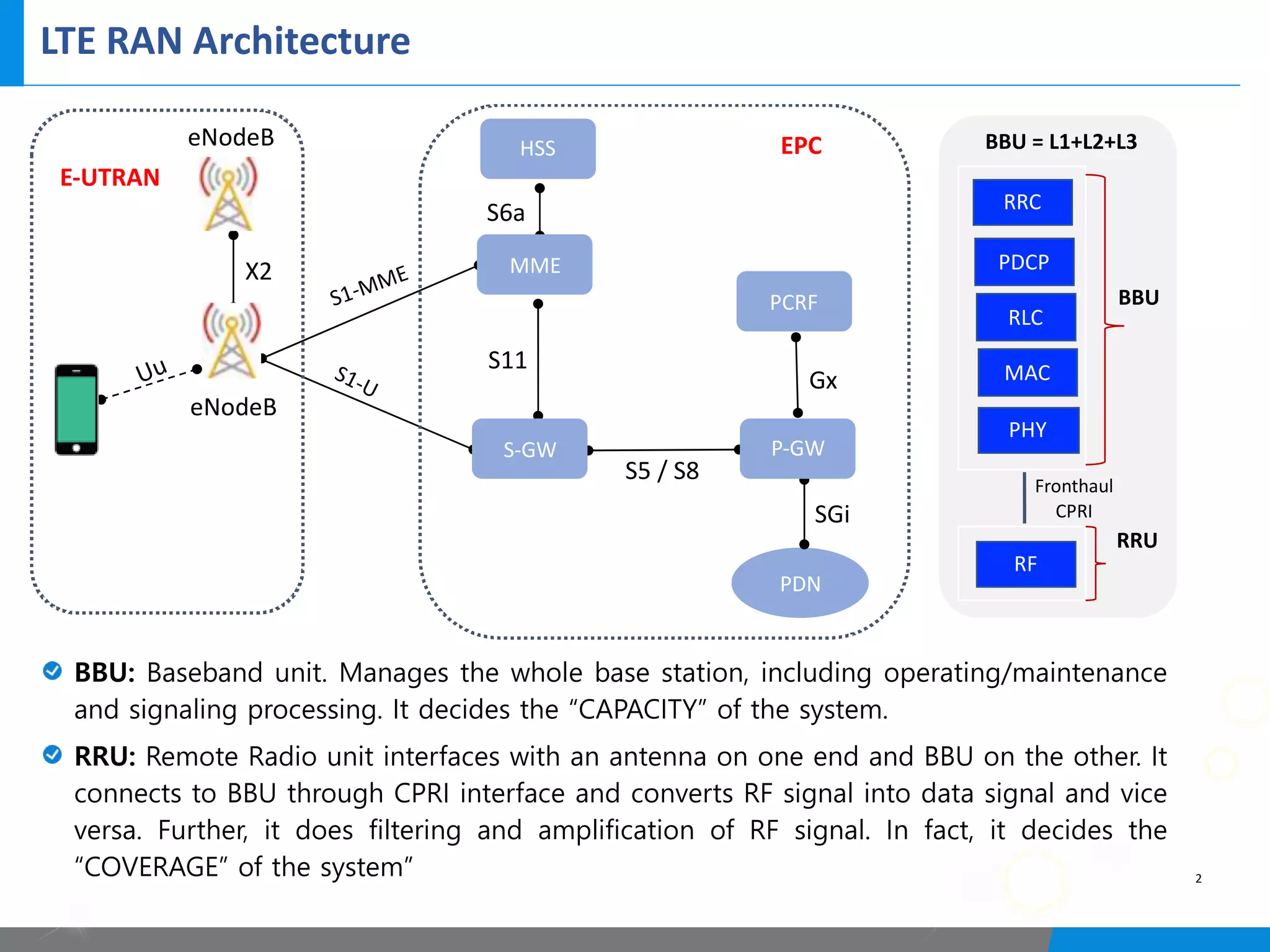
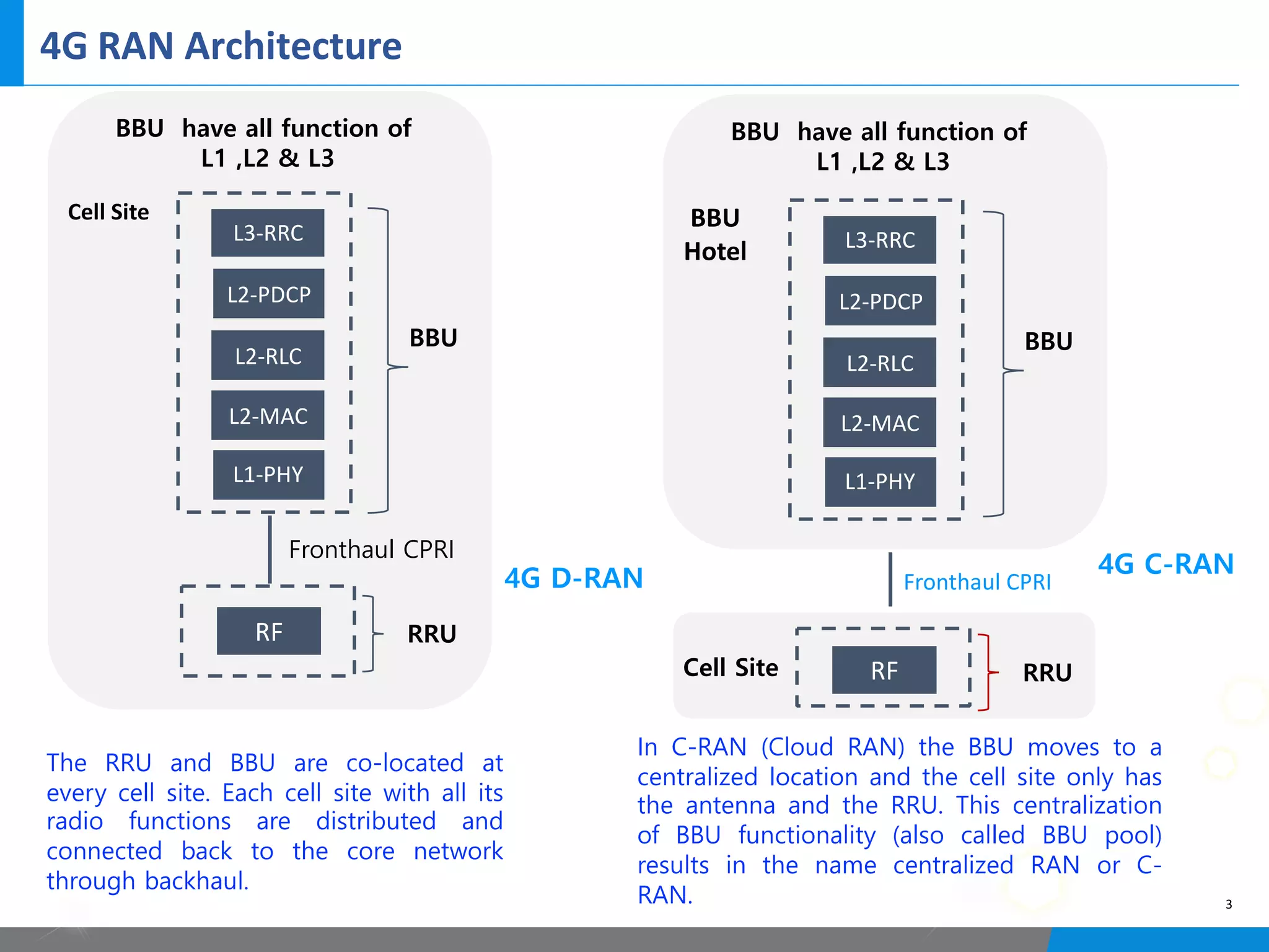
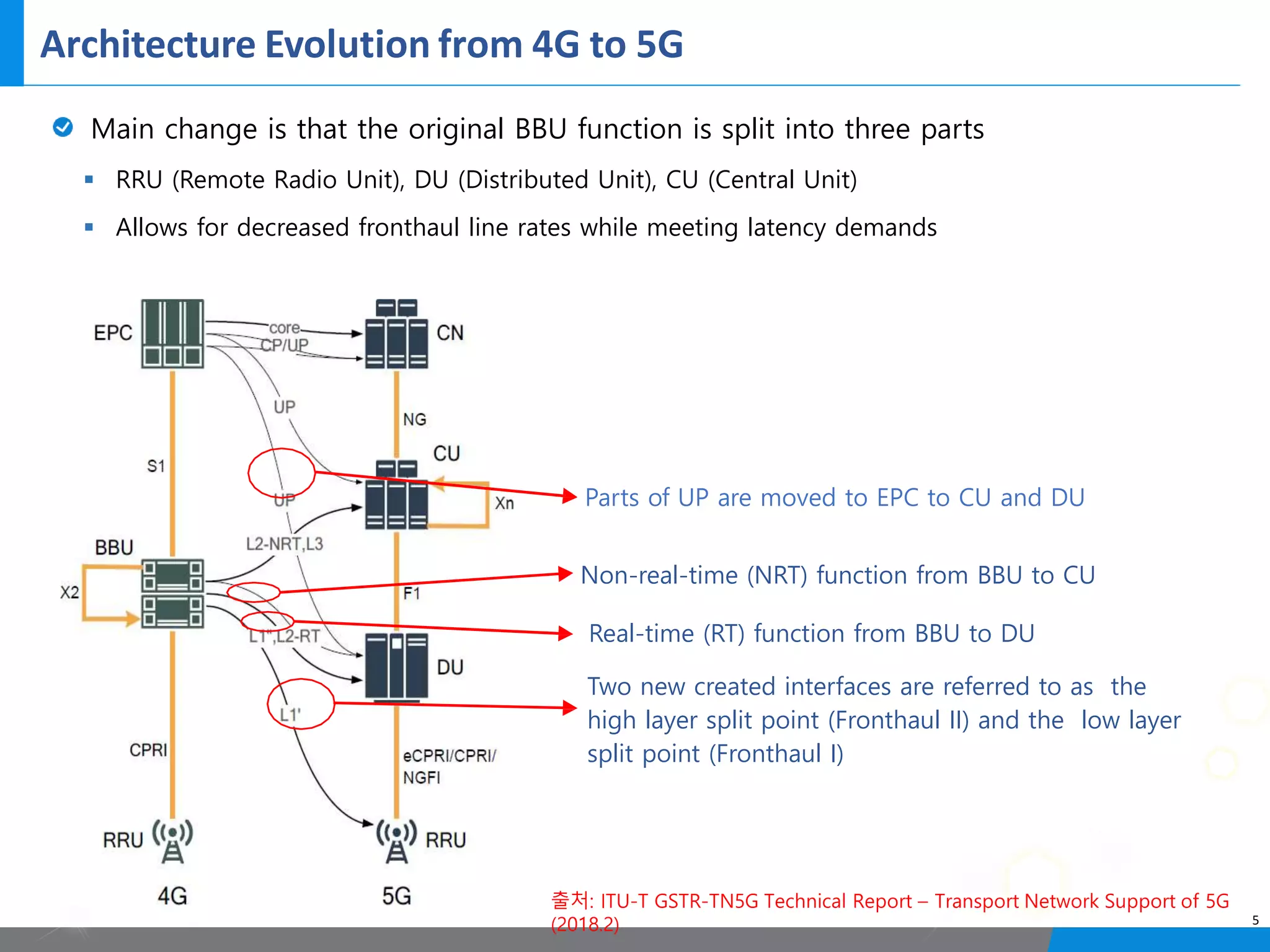
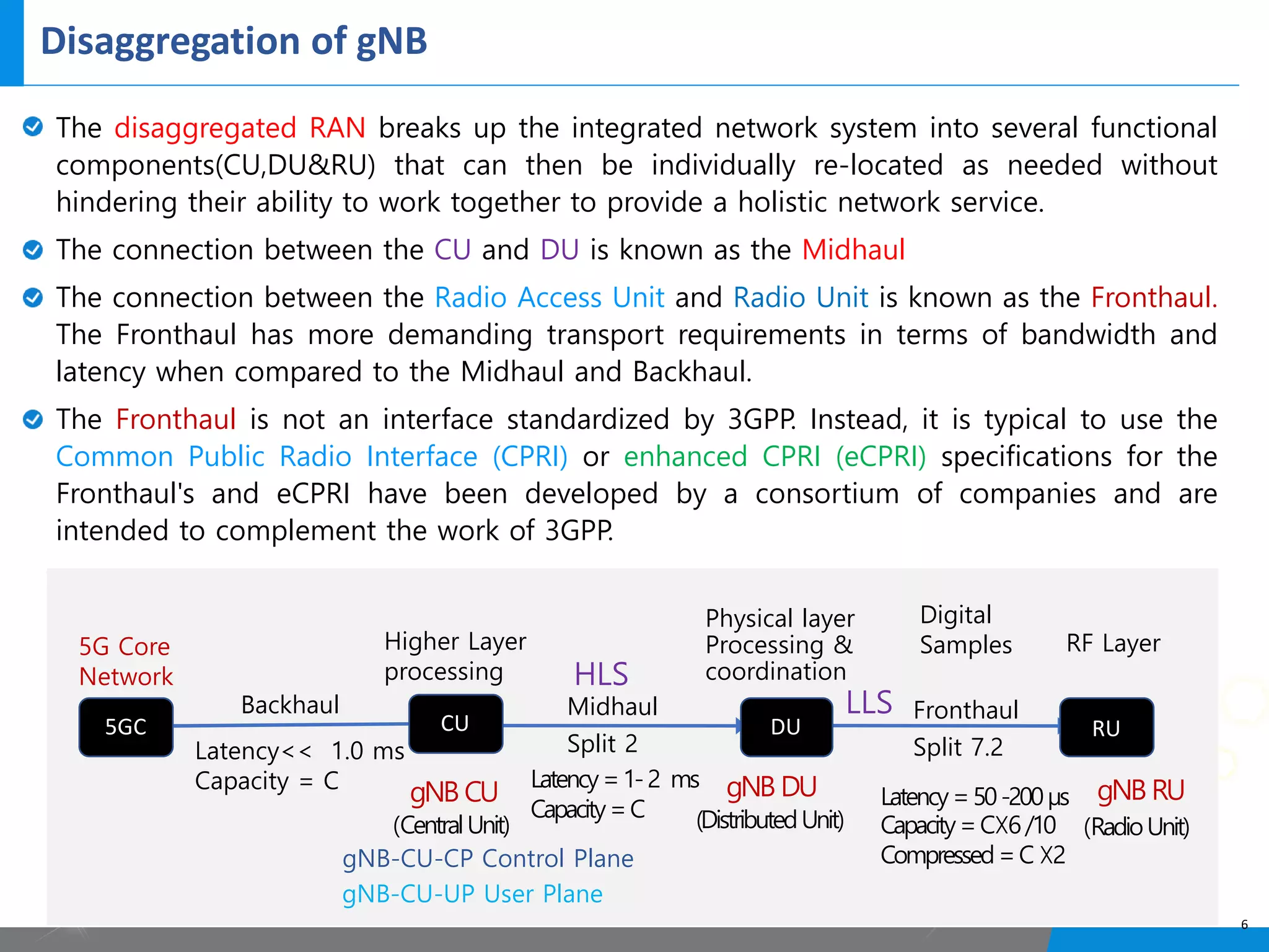
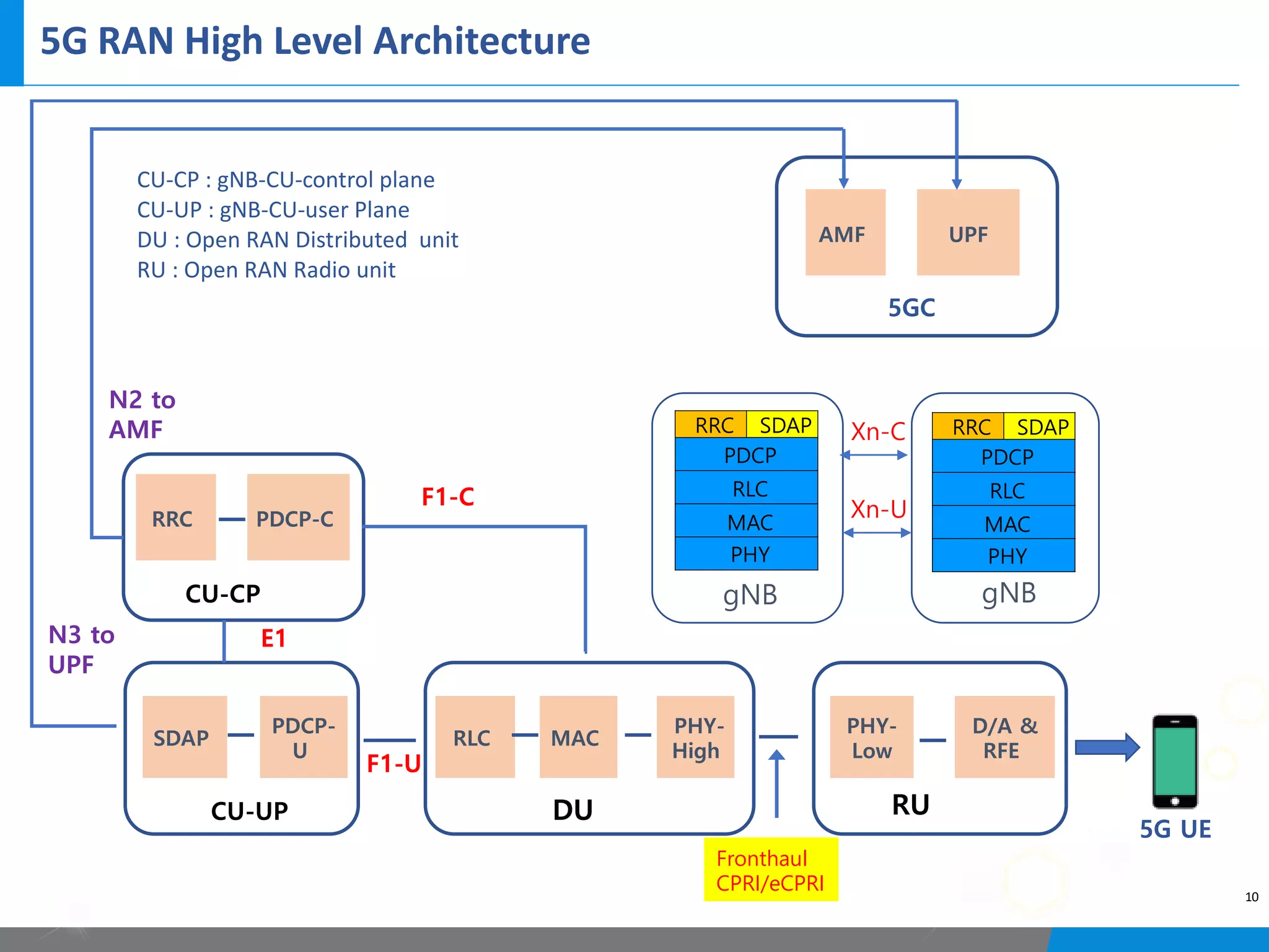
5G Overview
Prepared: Hemraj Kumar
Senior 5G Technology Consultant
LTE RAN Architecture
2
eNodeB
eNodeB
X2
S1-MME
S1-U
S5 / S8
S11
S6a
Gx
PDN
SGi
Uu
E-UTRAN
EPC
MME
S-GW P-GW
PCRF
HSS
RRC
PDCP
RLC
MAC
PHY
RF
BBU
RRU
Fronthaul
CPRI
BBU = L1+L2+L3
BBU: Baseband unit. Manages the whole base station, including operating/maintenance
and signaling processing. It decides the “CAPACITY” of the system.
RRU: Remote Radio unit interfaces with an antenna on one end and BBU on the other. It
connects to BBU through CPRI interface and converts RF signal into data signal and vice
versa. Further, it does filtering and amplification of RF signal. In fact, it decides the
“COVERAGE” of the system”
4G RAN Architecture
NG-RAN Overall Architecture
4
Architecture Evolution from 4G to 5G
출처: ITU-T GSTR-TN5G Technical Report – Transport Network Support of 5G
(2018.2) 5
Main change is that the original BBU function is split into three parts
§ RRU (Remote Radio Unit), DU (Distributed Unit), CU (Central Unit)
§ Allows for decreased fronthaul line rates while meeting latency demands
Parts of UP are moved to EPC to CU and DU
Non-real-time (NRT) function from BBU to CU
Real-time (RT) function from BBU to DU
Two new created interfaces are referred to as the
high layer split point (Fronthaul II) and the low layer
split point (Fronthaul I)
Disaggregation of gNB
The disaggregated RAN breaks up the integrated network system into several functional
components(CU,DU&RU) that can then be individually re-located as needed without
hindering their ability to work together to provide a holistic network service.
The connection between the CU and DU is known as the Midhaul
The connection between the Radio Access Unit and Radio Unit is known as the Fronthaul.
The Fronthaul has more demanding transport requirements in terms of bandwidth and
latency when compared to the Midhaul and Backhaul.
The Fronthaul is not an interface standardized by 3GPP. Instead, it is typical to use the
Common Public Radio Interface (CPRI) or enhanced CPRI (eCPRI) specifications for the
Fronthaul's and eCPRI have been developed by a consortium of companies and are
intended to complement the work of 3GPP.
6
5GC CU DU RU
5G Core
Network
Backhaul
gNB CU
(CentralUnit)
gNB-CU-CP Control Plane
gNB-CU-UP User Plane
gNB DU
(DistributedUnit)
gNB RU
(RadioUnit)
Midhaul
Split 2
Fronthaul
Split 7.2
Higher Layer
processing
Digital
Samples RF Layer
Latency=50-200µs
Capacity=C☓6/10
Compressed=C☓2
Latency=1-2 ms
Capacity=C
Latency<< 1.0 ms
Capacity = C
Physical layer
Processing &
coordination
LLS
HLS
5GC CU DU RU
CU-DU Split of gNB
7
Contrary to the 4G RAN, the 5G NR logical node, the gNB, is split between Central
Units (CUs) and DUs.
The benefits for such an architecture are:
§ Flexible hardware implementation
§ Coordination of performance
features, load management and
real time performance optimization
§ adaptation to various use cases
The split of the NR functions between CU and DUs is shown in above Figure
The choice of a split between Packet Data Convergence Protocol (PDCP) and Radio
link control (RLC) was driven by the reason that the split between MN and SN in DC
configuration is the same.
gNB-CU
gNB-DU gNB-DU
F1
F1 F1
gNB
RRC
SDAP
PDCP
RLC
MAC
PHY
CUPS(Control & User Plane Separation)
8
The gNB-CU is split into CP and UP for flexible dimensioning and topology.
It allows mobile service providers to bring the service closer to the user & reduced the
user plane latency.
5G services based around massive Machine Type Communications (mMTC), Ultra
Reliable and Low Latency Communications (URLLC), Fixed Wireless Access (FWA), and
new industry verticals will generate unique traffic patterns compared to typical mobile
data service.
gNB-CU-CP
gNB-CU-UP
gNB-CU-UP
gNB-CU-UP
gNB-DU gNB-DU
E1
E1
E1
F1-C
F1-C
F
1
-
U
F
1
-
U
F
1
-
U
F
1
-
U
F
1
-
U
F
1
-
U
The Conventional CUs with fixed
Control and User Plane (CU/UP)
resources are not suitable to
support NR traffic pattern.
In fact, for the majority of the
most exciting applications of
5G, CUPS is required—virtual
reality gaming, smart cities,
emergency response services—
because they can’t tolerate
latency.
CUPS(Control & User Plane Separation)
9
Single gNB-CU-CP in charge of controlling several gNB-CU-UPs and gNB-DUs.
In a live network deployment a single gNB-CU-CP will control hundreds of gNB-DUs
and maybe several gNB-CU-UPs. This is why it is misleading to compare the connectivity
of a gNB-CU-CP with that of a LTE eNB. Rather it could be compared with a UTRAN
RNC controlling a similar number of 3G base stations.
F1AP is used for communication between gNB-CU CP and its gNB-DUs while the E1AP
is the protocol that connects the gNB-CU-CP with surrounding gNB-CU-UPs.
Call-related control plane procedures of F1AP and E1AP are very similar to what is
known from NGAP. There is a UE context established between the gNB-CU CP and the
gNB-DU. On F1-U a GTP tunnel is established for user plane transport. At the same time
an E1 Bearer Context in gNB-CU-CP and gNB-CU-UP keeps track of the most relevant
user plane transport parameters.
The connectivity between a gNB-CU-UP and a gNB-DU is established by the gNB-CU-
CP using Bearer Context Management functions.
The gNB-CU-CP selects the appropriate gNB-CU-UP(s) for the requested services for the
UE.
Data forwarding between gNB-CU-UPs during intra-gNB-CU-CP handover within a gNB
may be supported by Xn-U.
5G RAN High Level Architecture
10
SDAP
PDCP-
U
RLC MAC
PHY-
High
PHY-
Low
D/A &
RFE
RRC PDCP-C
CU-UP DU RU
CU-CP
N2 to
AMF
N3 to
UPF
5G UE
AMF UPF
5GC
F1-C
CU-CP : gNB-CU-control plane
CU-UP : gNB-CU-user Plane
DU : Open RAN Distributed unit
RU : Open RAN Radio unit
F1-U
E1
Fronthaul
CPRI/eCPRI
RRC SDAP
PDCP
RLC
MAC
PHY
RRC SDAP
PDCP
RLC
MAC
PHY
Xn-C
Xn-U
gNB gNB
5G RAN Split Architecture
11
The core of the whole thing is the gNB-Central Unit for the Control Plane (gNB-CU-CP).
This function communicates directly with the UE using the NR RRC protocol. It also
"talks" to the 5G Core Network represented by the AMF using the NGAP, a protocol
very similar to the S1AP known from E-UTRAN. Neighboring 5G base stations are
contacted using the XnAP, neighboring eNBs can be reached by using X2AP.
The other virtual functions of the gNB are the Central Units for User Plane (gNB-CU -
UP) and the Distributed Units (gNB-DU). While the gNB-CU-UP is responsible for
handling the transport of payload the gNB-DUs deal with all the allocation of radio
resources, especially the scheduling. As a result the lower layer radio interface
protocols, especially RLC and MAC terminate in the gNB-DUs.

5 g ran architcture

  • 1.
    5G Overview Prepared: HemrajKumar Senior 5G Technology Consultant
  • 2.
    LTE RAN Architecture 2 eNodeB eNodeB X2 S1-MME S1-U S5/ S8 S11 S6a Gx PDN SGi Uu E-UTRAN EPC MME S-GW P-GW PCRF HSS RRC PDCP RLC MAC PHY RF BBU RRU Fronthaul CPRI BBU = L1+L2+L3 BBU: Baseband unit. Manages the whole base station, including operating/maintenance and signaling processing. It decides the “CAPACITY” of the system. RRU: Remote Radio unit interfaces with an antenna on one end and BBU on the other. It connects to BBU through CPRI interface and converts RF signal into data signal and vice versa. Further, it does filtering and amplification of RF signal. In fact, it decides the “COVERAGE” of the system”
  • 3.
  • 4.
  • 5.
    Architecture Evolution from4G to 5G 출처: ITU-T GSTR-TN5G Technical Report – Transport Network Support of 5G (2018.2) 5 Main change is that the original BBU function is split into three parts § RRU (Remote Radio Unit), DU (Distributed Unit), CU (Central Unit) § Allows for decreased fronthaul line rates while meeting latency demands Parts of UP are moved to EPC to CU and DU Non-real-time (NRT) function from BBU to CU Real-time (RT) function from BBU to DU Two new created interfaces are referred to as the high layer split point (Fronthaul II) and the low layer split point (Fronthaul I)
  • 6.
    Disaggregation of gNB Thedisaggregated RAN breaks up the integrated network system into several functional components(CU,DU&RU) that can then be individually re-located as needed without hindering their ability to work together to provide a holistic network service. The connection between the CU and DU is known as the Midhaul The connection between the Radio Access Unit and Radio Unit is known as the Fronthaul. The Fronthaul has more demanding transport requirements in terms of bandwidth and latency when compared to the Midhaul and Backhaul. The Fronthaul is not an interface standardized by 3GPP. Instead, it is typical to use the Common Public Radio Interface (CPRI) or enhanced CPRI (eCPRI) specifications for the Fronthaul's and eCPRI have been developed by a consortium of companies and are intended to complement the work of 3GPP. 6 5GC CU DU RU 5G Core Network Backhaul gNB CU (CentralUnit) gNB-CU-CP Control Plane gNB-CU-UP User Plane gNB DU (DistributedUnit) gNB RU (RadioUnit) Midhaul Split 2 Fronthaul Split 7.2 Higher Layer processing Digital Samples RF Layer Latency=50-200µs Capacity=C☓6/10 Compressed=C☓2 Latency=1-2 ms Capacity=C Latency<< 1.0 ms Capacity = C Physical layer Processing & coordination LLS HLS 5GC CU DU RU
  • 7.
    CU-DU Split ofgNB 7 Contrary to the 4G RAN, the 5G NR logical node, the gNB, is split between Central Units (CUs) and DUs. The benefits for such an architecture are: § Flexible hardware implementation § Coordination of performance features, load management and real time performance optimization § adaptation to various use cases The split of the NR functions between CU and DUs is shown in above Figure The choice of a split between Packet Data Convergence Protocol (PDCP) and Radio link control (RLC) was driven by the reason that the split between MN and SN in DC configuration is the same. gNB-CU gNB-DU gNB-DU F1 F1 F1 gNB RRC SDAP PDCP RLC MAC PHY
  • 8.
    CUPS(Control & UserPlane Separation) 8 The gNB-CU is split into CP and UP for flexible dimensioning and topology. It allows mobile service providers to bring the service closer to the user & reduced the user plane latency. 5G services based around massive Machine Type Communications (mMTC), Ultra Reliable and Low Latency Communications (URLLC), Fixed Wireless Access (FWA), and new industry verticals will generate unique traffic patterns compared to typical mobile data service. gNB-CU-CP gNB-CU-UP gNB-CU-UP gNB-CU-UP gNB-DU gNB-DU E1 E1 E1 F1-C F1-C F 1 - U F 1 - U F 1 - U F 1 - U F 1 - U F 1 - U The Conventional CUs with fixed Control and User Plane (CU/UP) resources are not suitable to support NR traffic pattern. In fact, for the majority of the most exciting applications of 5G, CUPS is required—virtual reality gaming, smart cities, emergency response services— because they can’t tolerate latency.
  • 9.
    CUPS(Control & UserPlane Separation) 9 Single gNB-CU-CP in charge of controlling several gNB-CU-UPs and gNB-DUs. In a live network deployment a single gNB-CU-CP will control hundreds of gNB-DUs and maybe several gNB-CU-UPs. This is why it is misleading to compare the connectivity of a gNB-CU-CP with that of a LTE eNB. Rather it could be compared with a UTRAN RNC controlling a similar number of 3G base stations. F1AP is used for communication between gNB-CU CP and its gNB-DUs while the E1AP is the protocol that connects the gNB-CU-CP with surrounding gNB-CU-UPs. Call-related control plane procedures of F1AP and E1AP are very similar to what is known from NGAP. There is a UE context established between the gNB-CU CP and the gNB-DU. On F1-U a GTP tunnel is established for user plane transport. At the same time an E1 Bearer Context in gNB-CU-CP and gNB-CU-UP keeps track of the most relevant user plane transport parameters. The connectivity between a gNB-CU-UP and a gNB-DU is established by the gNB-CU- CP using Bearer Context Management functions. The gNB-CU-CP selects the appropriate gNB-CU-UP(s) for the requested services for the UE. Data forwarding between gNB-CU-UPs during intra-gNB-CU-CP handover within a gNB may be supported by Xn-U.
  • 10.
    5G RAN HighLevel Architecture 10 SDAP PDCP- U RLC MAC PHY- High PHY- Low D/A & RFE RRC PDCP-C CU-UP DU RU CU-CP N2 to AMF N3 to UPF 5G UE AMF UPF 5GC F1-C CU-CP : gNB-CU-control plane CU-UP : gNB-CU-user Plane DU : Open RAN Distributed unit RU : Open RAN Radio unit F1-U E1 Fronthaul CPRI/eCPRI RRC SDAP PDCP RLC MAC PHY RRC SDAP PDCP RLC MAC PHY Xn-C Xn-U gNB gNB
  • 11.
    5G RAN SplitArchitecture 11 The core of the whole thing is the gNB-Central Unit for the Control Plane (gNB-CU-CP). This function communicates directly with the UE using the NR RRC protocol. It also "talks" to the 5G Core Network represented by the AMF using the NGAP, a protocol very similar to the S1AP known from E-UTRAN. Neighboring 5G base stations are contacted using the XnAP, neighboring eNBs can be reached by using X2AP. The other virtual functions of the gNB are the Central Units for User Plane (gNB-CU - UP) and the Distributed Units (gNB-DU). While the gNB-CU-UP is responsible for handling the transport of payload the gNB-DUs deal with all the allocation of radio resources, especially the scheduling. As a result the lower layer radio interface protocols, especially RLC and MAC terminate in the gNB-DUs.