Downloaded 1,645 times
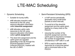
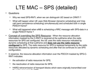
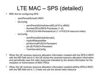
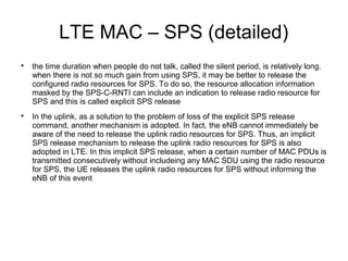
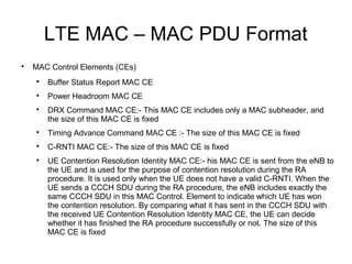
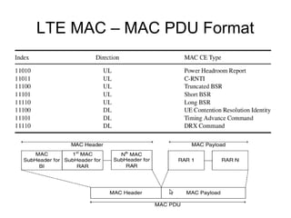

The document discusses LTE medium access control layer concepts. It describes dynamic and semi-persistent scheduling used by the eNB to allocate downlink and uplink radio resources to UEs. Semi-persistent scheduling is used for periodic traffic like VoIP to reduce signaling overhead compared to dynamic scheduling. It also discusses buffer status reporting where UEs indicate how much data they have to transmit, and scheduling requests where UEs request uplink resources from the eNB.