The document discusses the LTE attach call flow process, including:
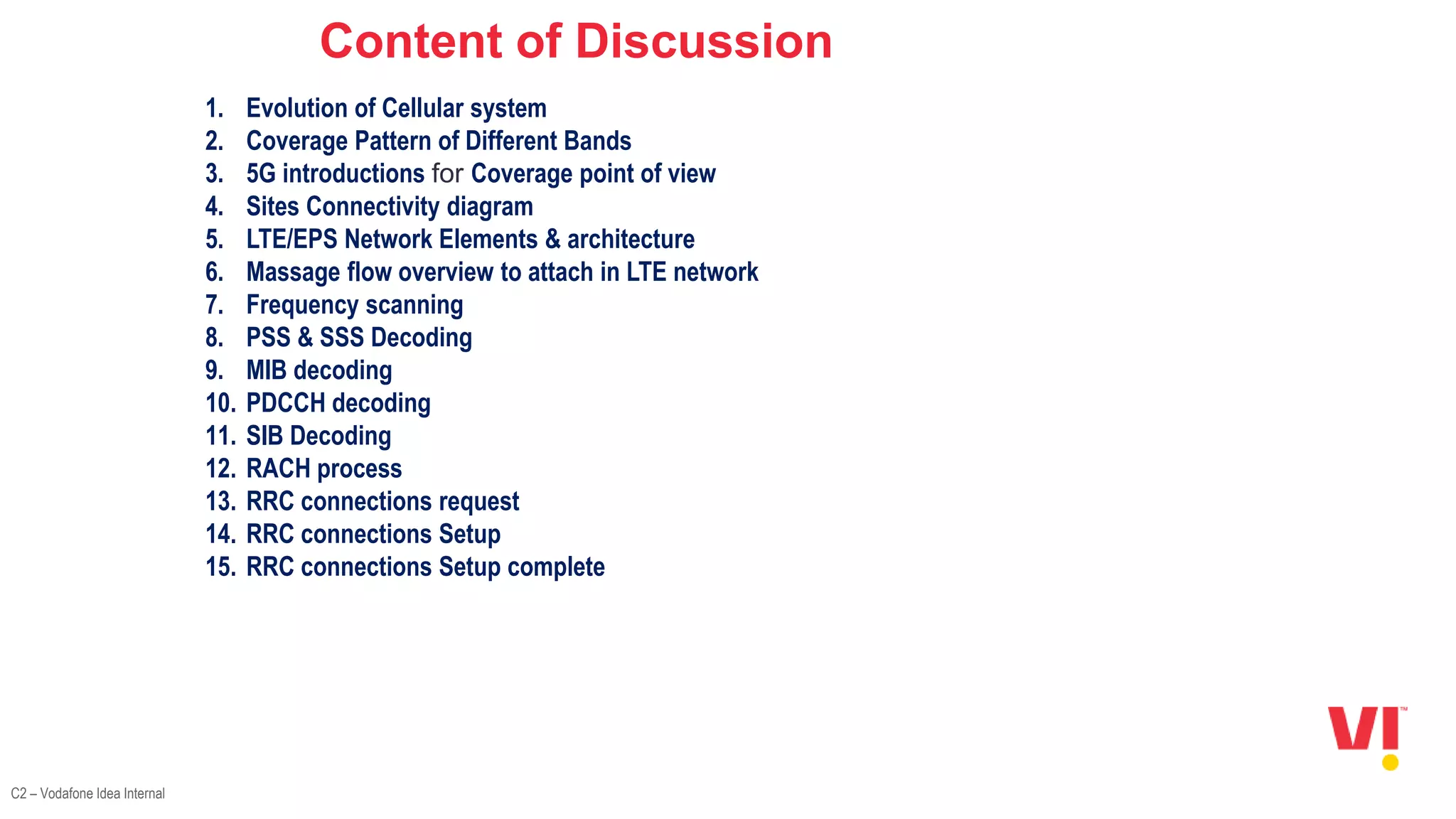
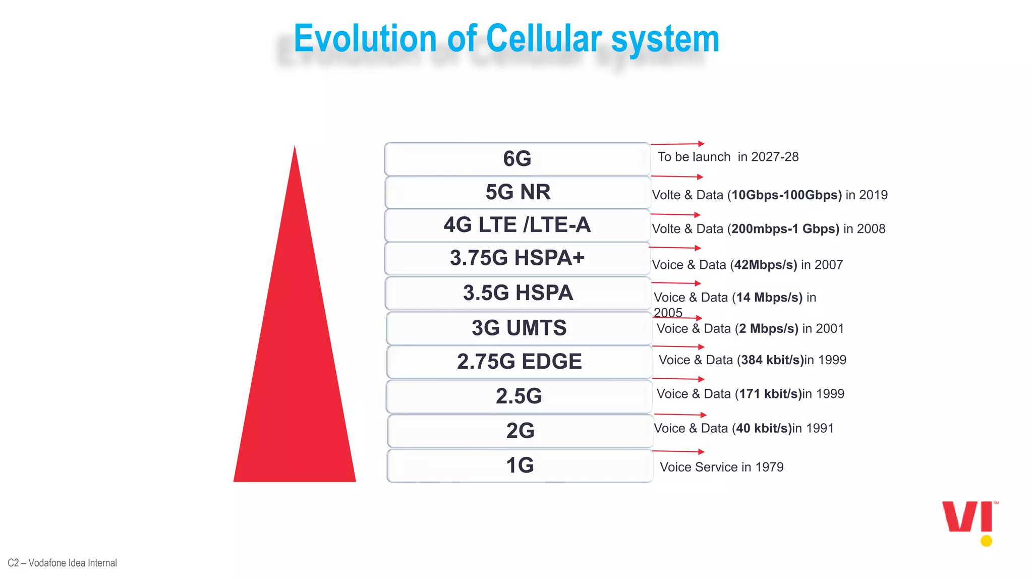
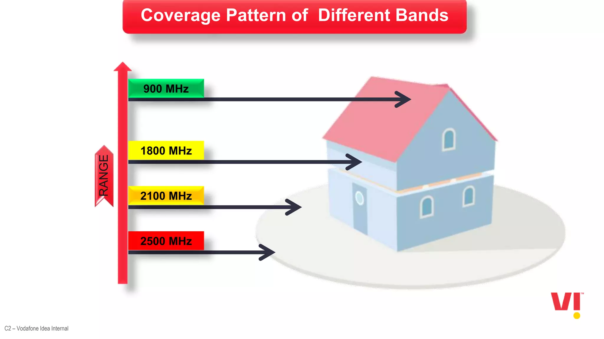
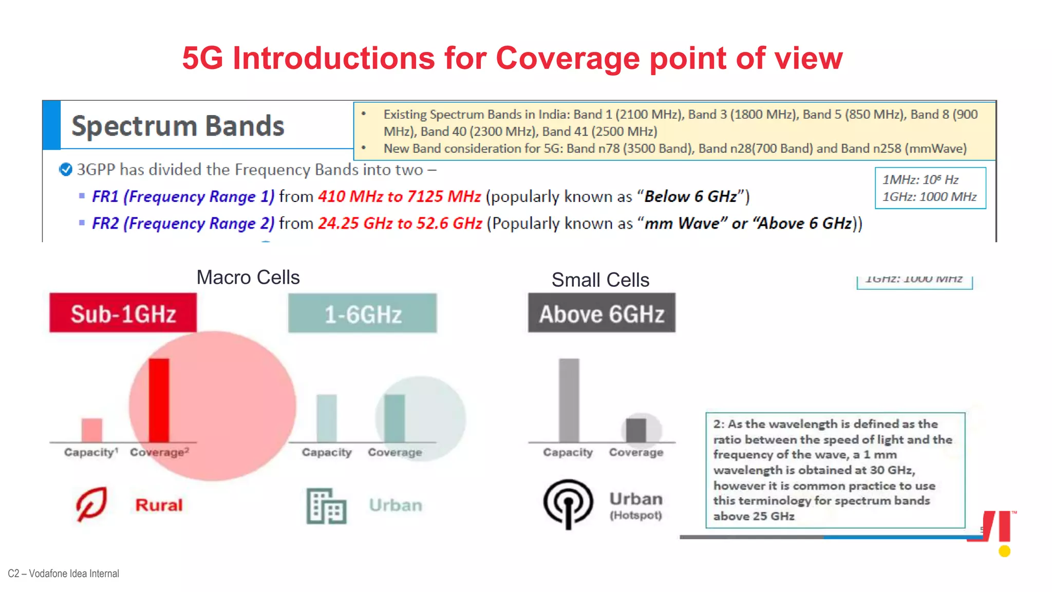
1. An overview of the evolution of cellular systems and the introduction of 5G.
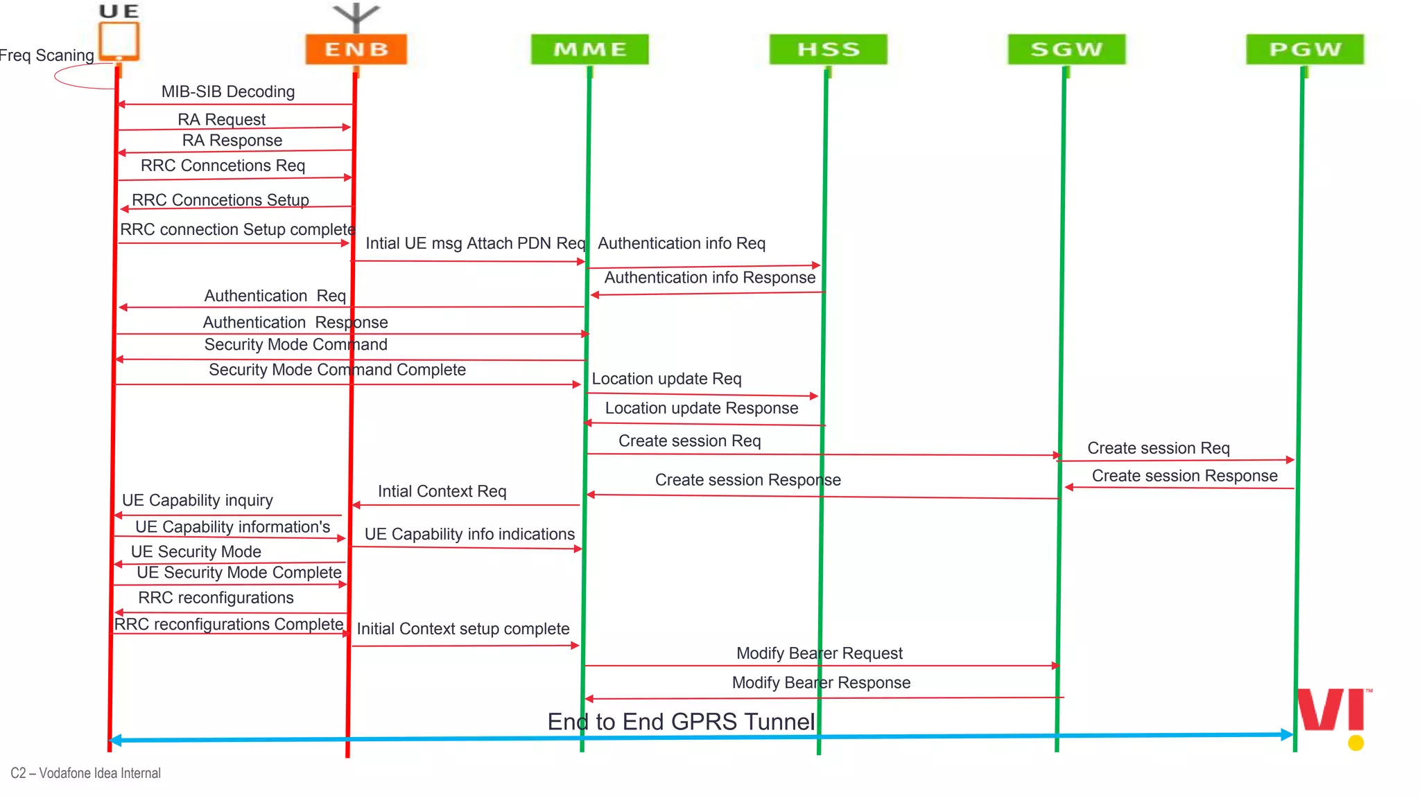
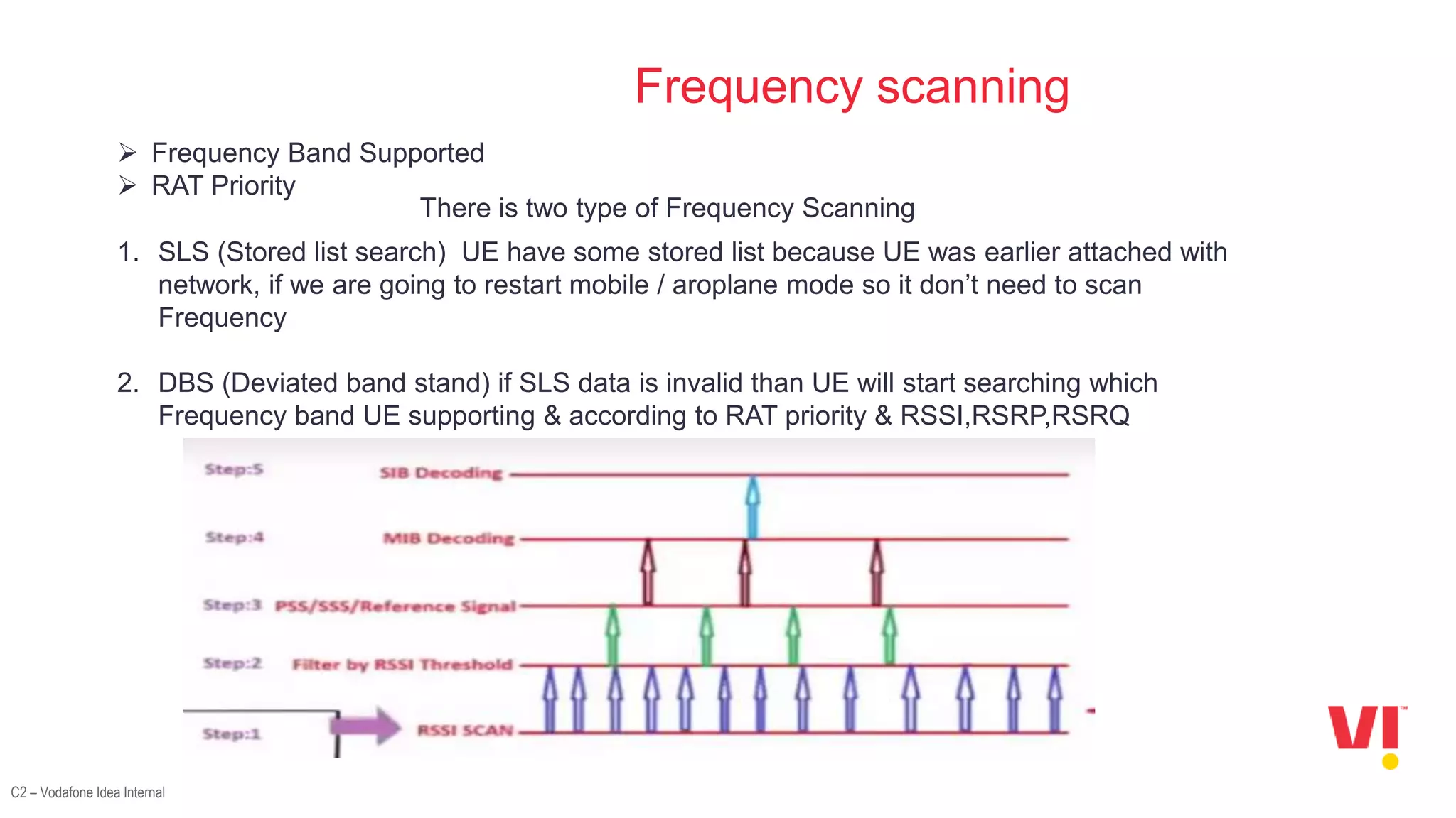
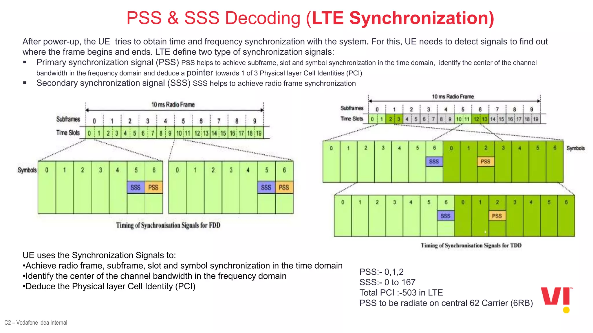
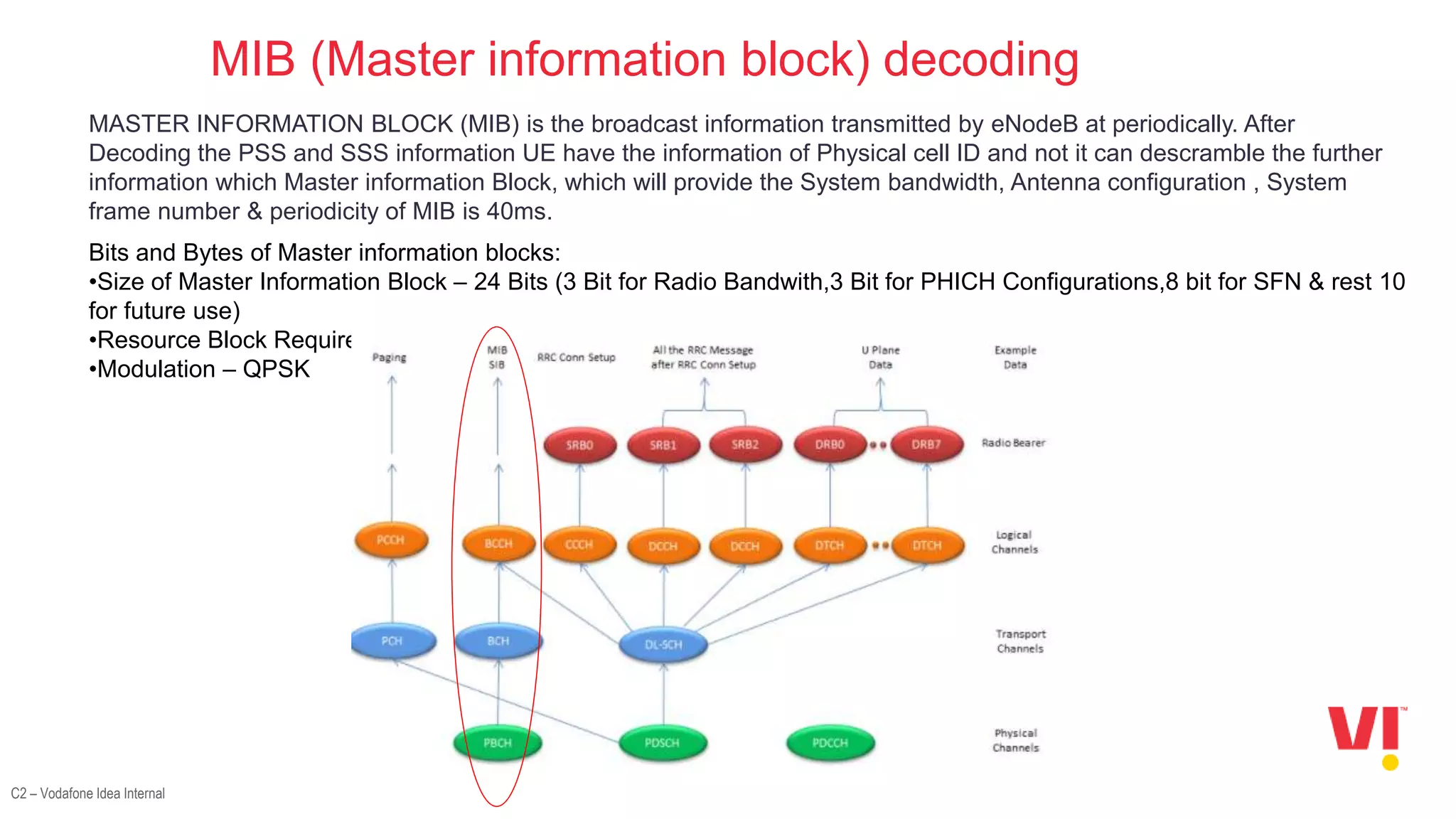
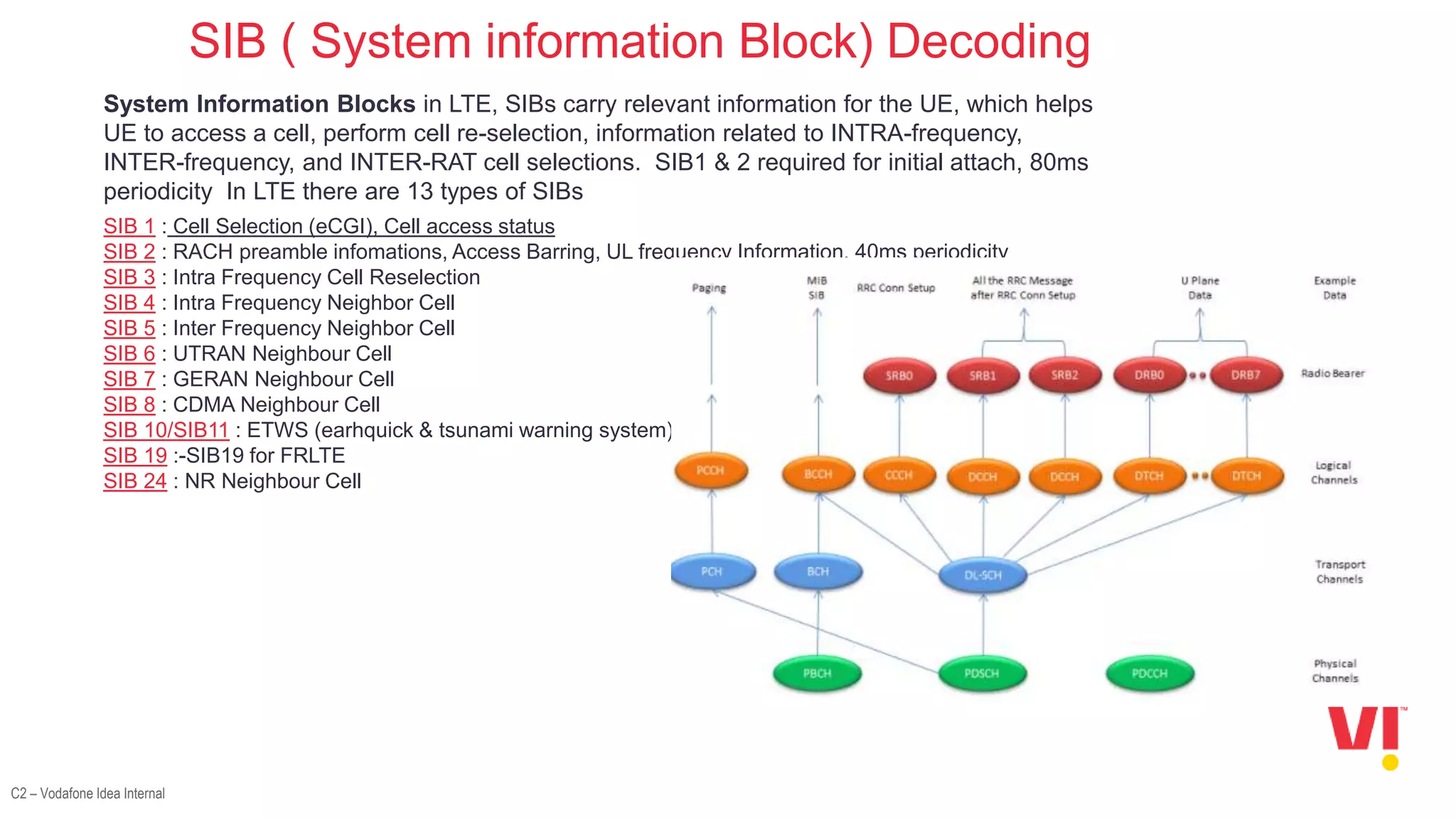
2. The decoding processes involved in LTE attach which include frequency scanning, decoding the PSS, SSS, MIB, PDCCH, and SIBs.
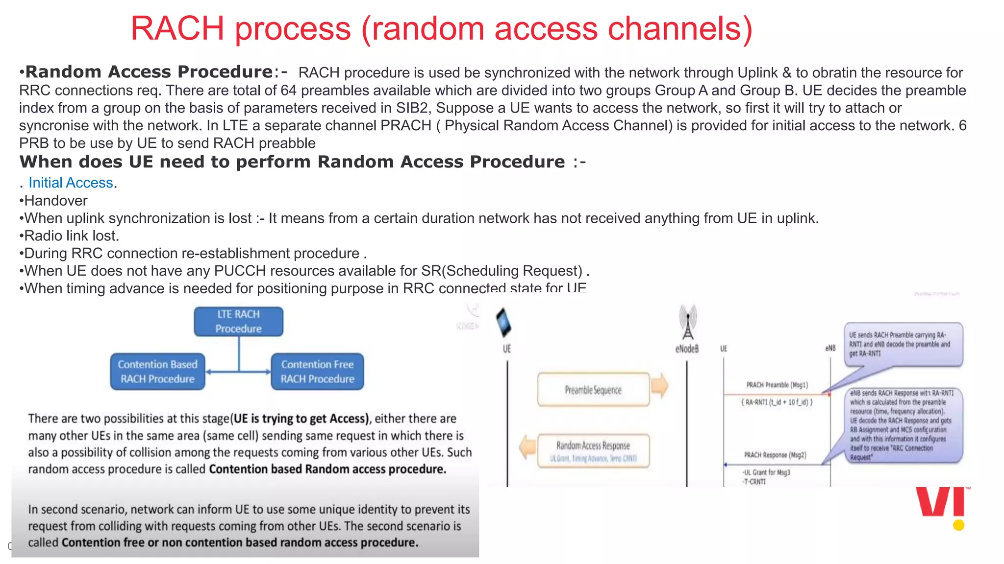
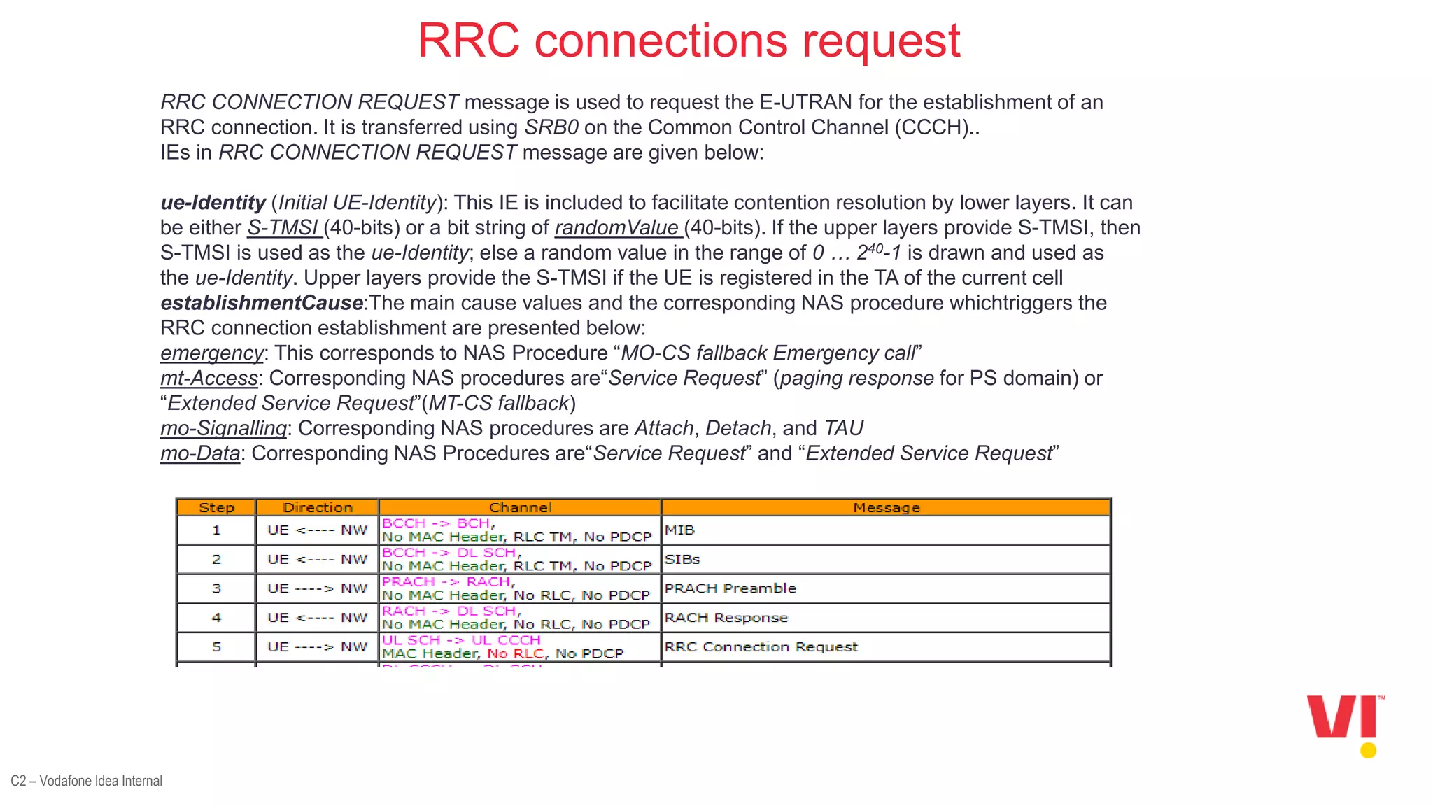
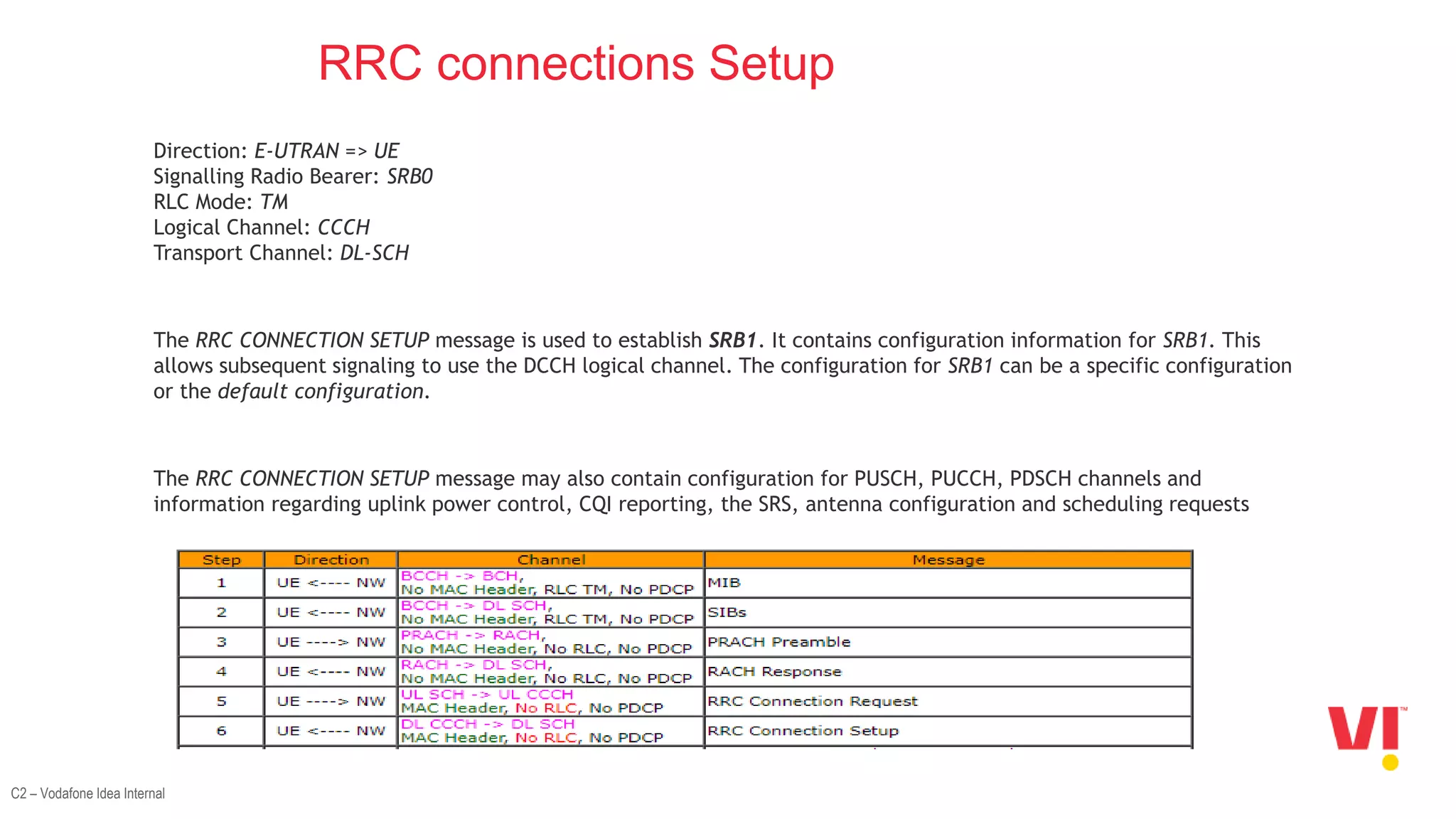
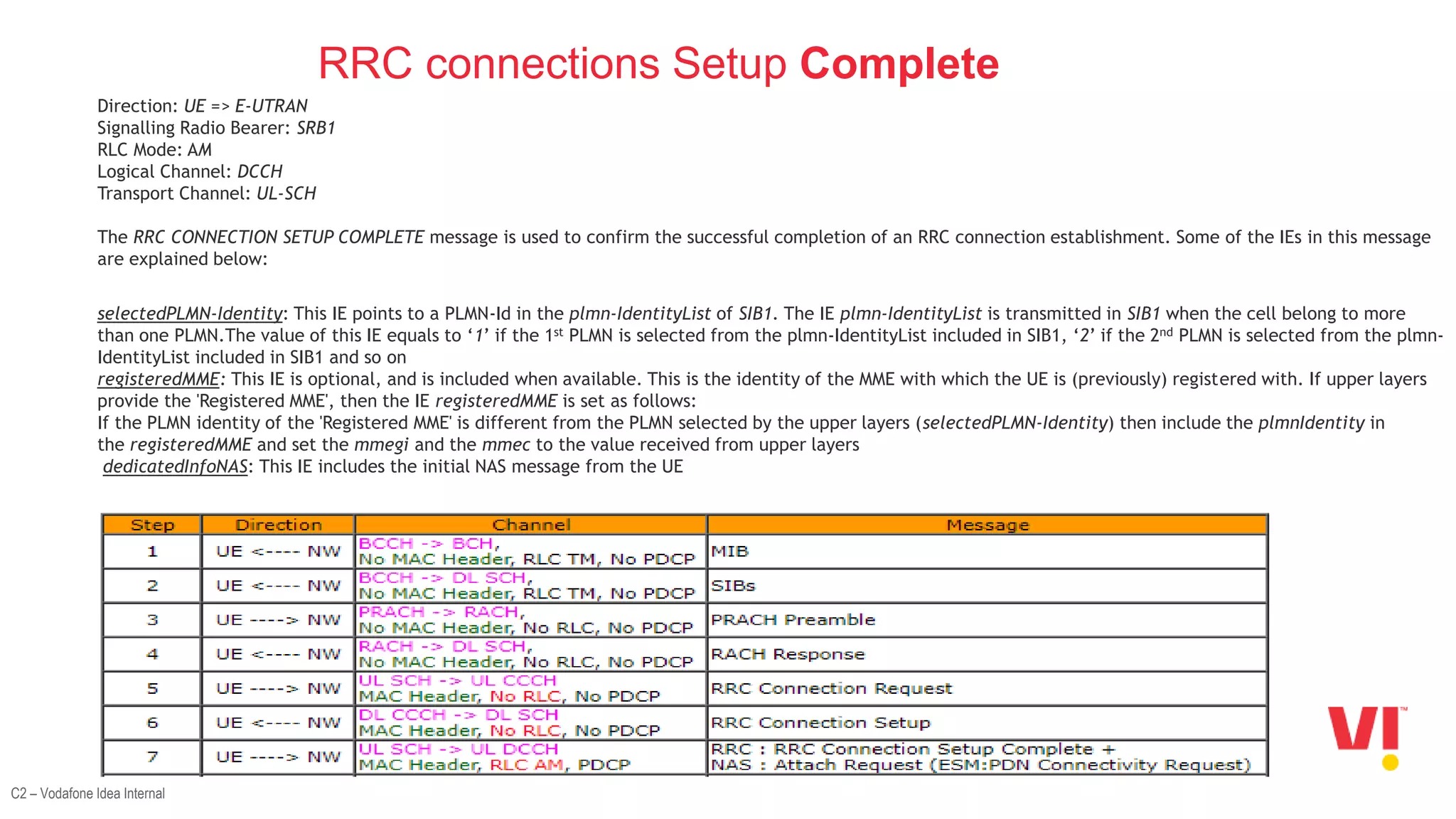
3. The steps in the LTE attach process such as the random access channel process, sending an RRC connection request, receiving an RRC connection setup, and responding with an RRC connection setup complete message.