SIB1 provides cell access related information such as PLMN identity, tracking area code, cell identity and access parameters. It is transmitted every 80ms in subframe 5. SIB2 contains radio resource configuration information including access class barring, RACH configuration, timers and power control. It provides parameters for random access, paging, physical channels and uplink power control. SIB1 and SIB2 carry essential system information from the network to user equipment about cell access and configuration.
System Information Blocksin LTE
SIB1
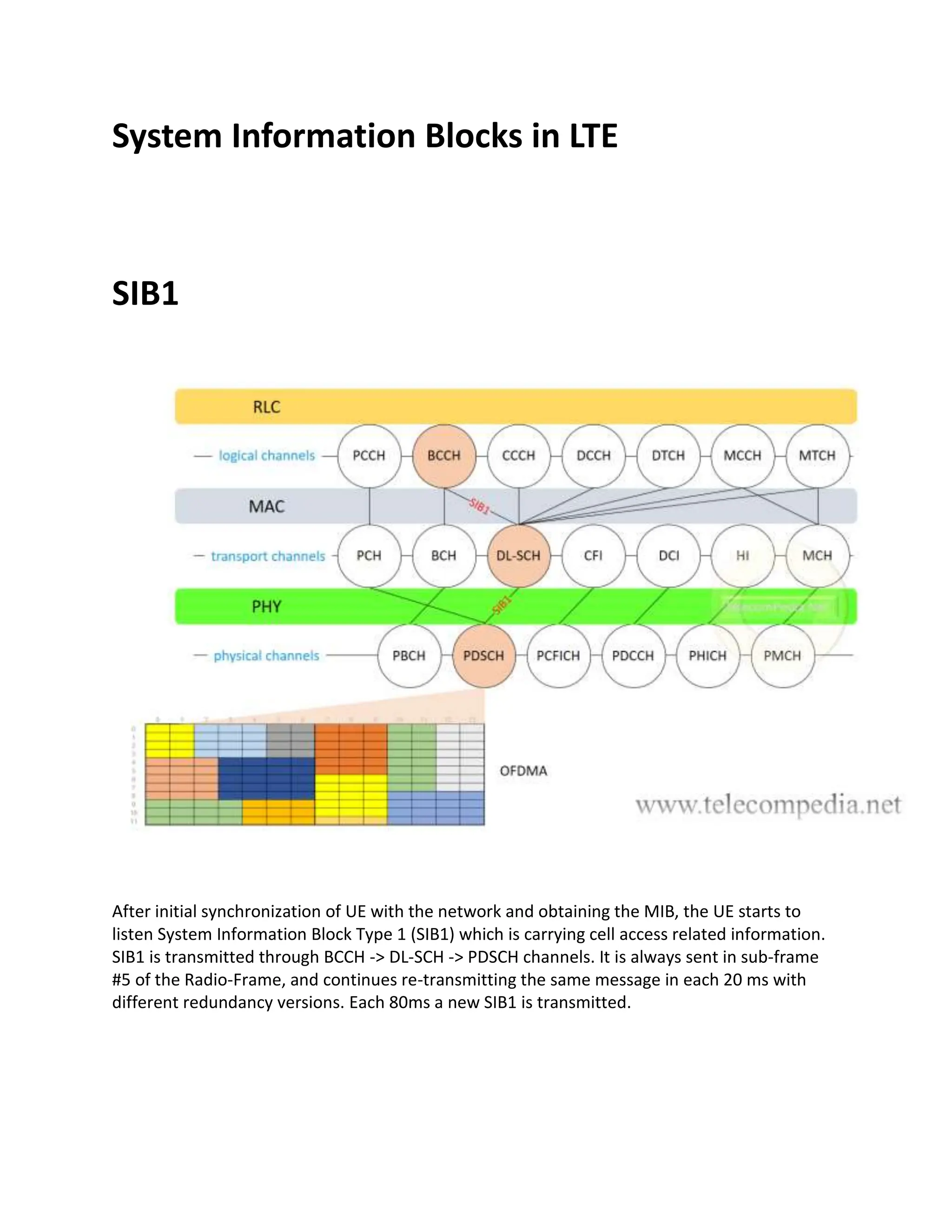
After initial synchronization of UE with the network and obtaining the MIB, the UE starts to
listen System Information Block Type 1 (SIB1) which is carrying cell access related information.
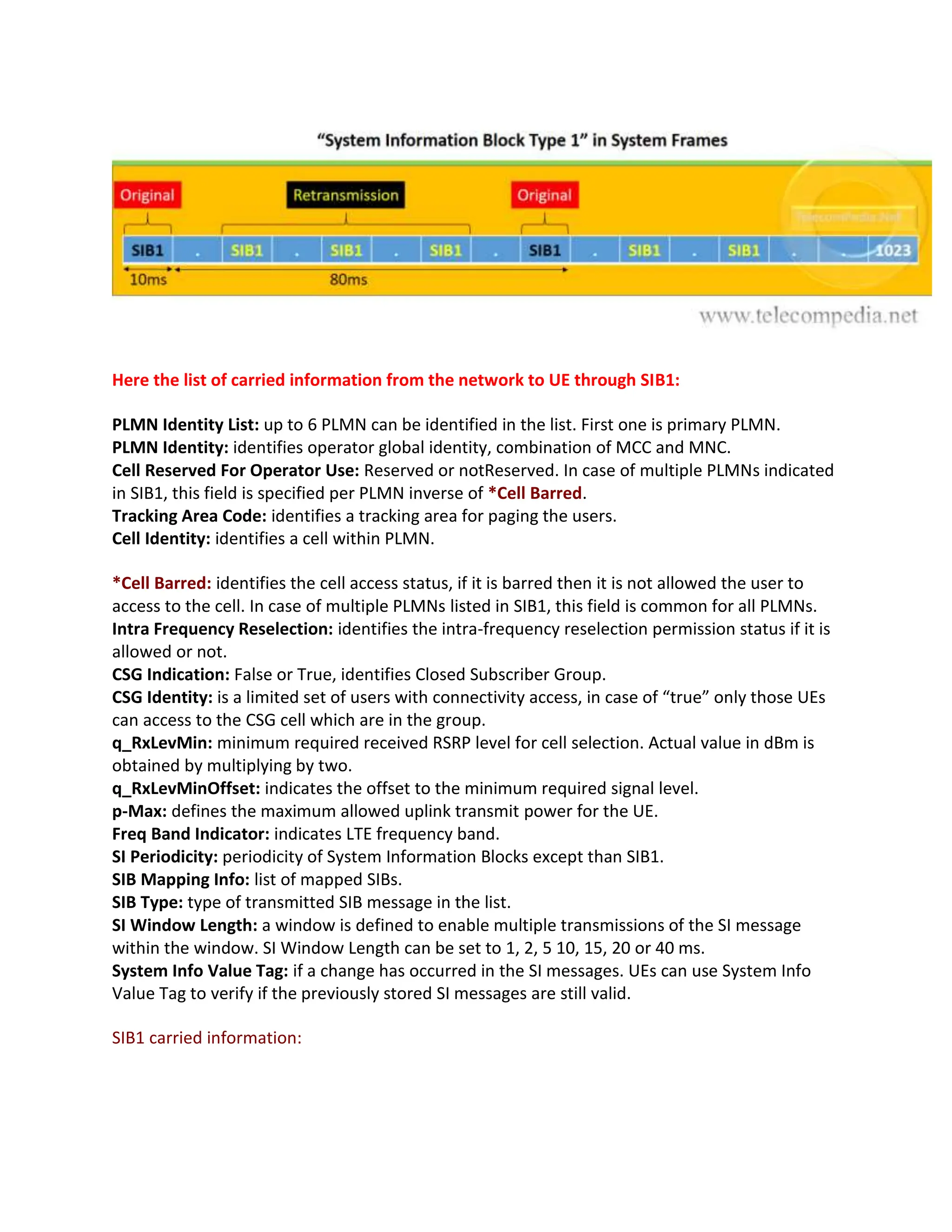
SIB1 is transmitted through BCCH -> DL-SCH -> PDSCH channels. It is always sent in sub-frame
#5 of the Radio-Frame, and continues re-transmitting the same message in each 20 ms with
different redundancy versions. Each 80ms a new SIB1 is transmitted.
2.
Here the listof carried information from the network to UE through SIB1:
PLMN Identity List: up to 6 PLMN can be identified in the list. First one is primary PLMN.
PLMN Identity: identifies operator global identity, combination of MCC and MNC.
Cell Reserved For Operator Use: Reserved or notReserved. In case of multiple PLMNs indicated
in SIB1, this field is specified per PLMN inverse of *Cell Barred.
Tracking Area Code: identifies a tracking area for paging the users.
Cell Identity: identifies a cell within PLMN.
*Cell Barred: identifies the cell access status, if it is barred then it is not allowed the user to
access to the cell. In case of multiple PLMNs listed in SIB1, this field is common for all PLMNs.
Intra Frequency Reselection: identifies the intra-frequency reselection permission status if it is
allowed or not.
CSG Indication: False or True, identifies Closed Subscriber Group.
CSG Identity: is a limited set of users with connectivity access, in case of “true” only those UEs
can access to the CSG cell which are in the group.
q_RxLevMin: minimum required received RSRP level for cell selection. Actual value in dBm is
obtained by multiplying by two.
q_RxLevMinOffset: indicates the offset to the minimum required signal level.
p-Max: defines the maximum allowed uplink transmit power for the UE.
Freq Band Indicator: indicates LTE frequency band.
SI Periodicity: periodicity of System Information Blocks except than SIB1.
SIB Mapping Info: list of mapped SIBs.
SIB Type: type of transmitted SIB message in the list.
SI Window Length: a window is defined to enable multiple transmissions of the SI message
within the window. SI Window Length can be set to 1, 2, 5 10, 15, 20 or 40 ms.
System Info Value Tag: if a change has occurred in the SI messages. UEs can use System Info
Value Tag to verify if the previously stored SI messages are still valid.
SIB1 carried information:
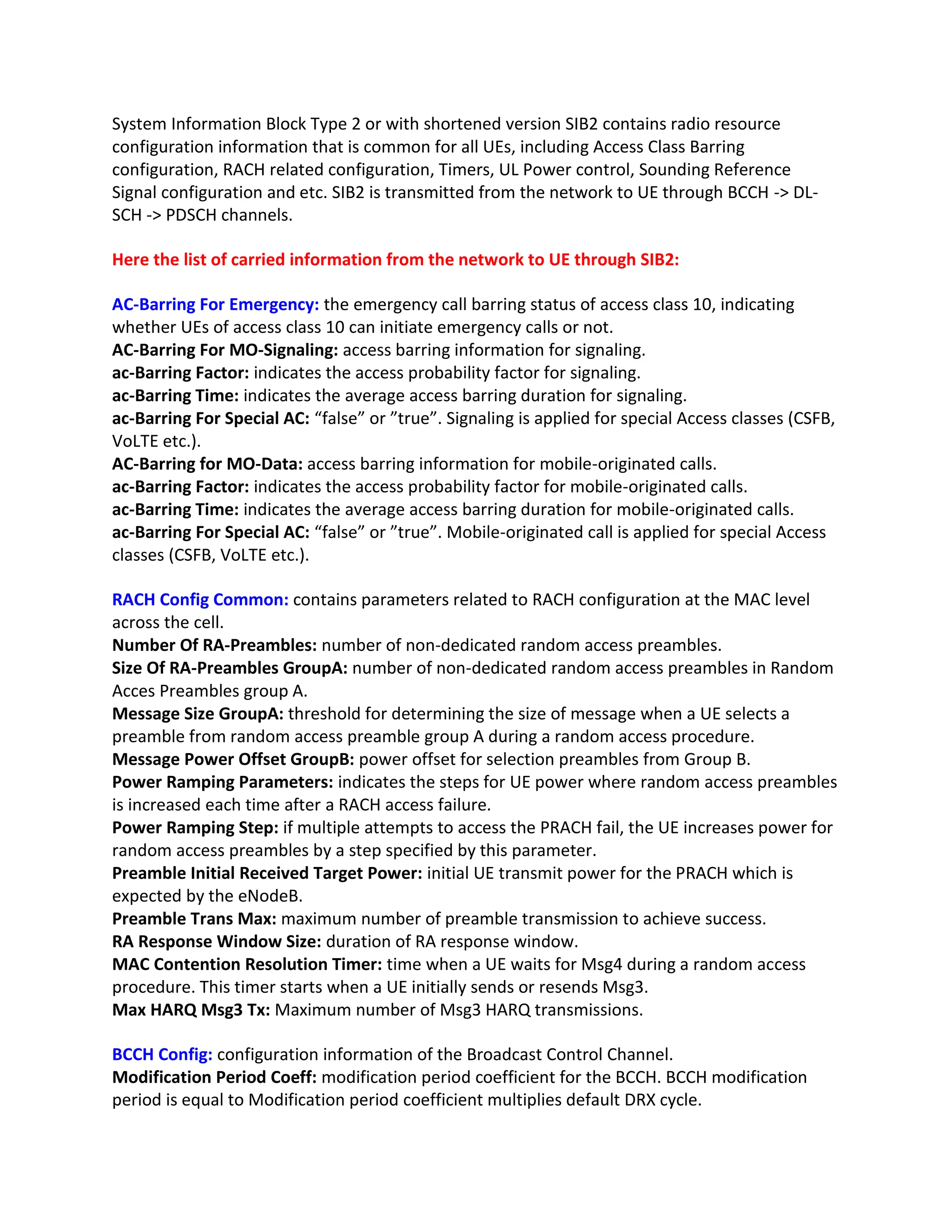
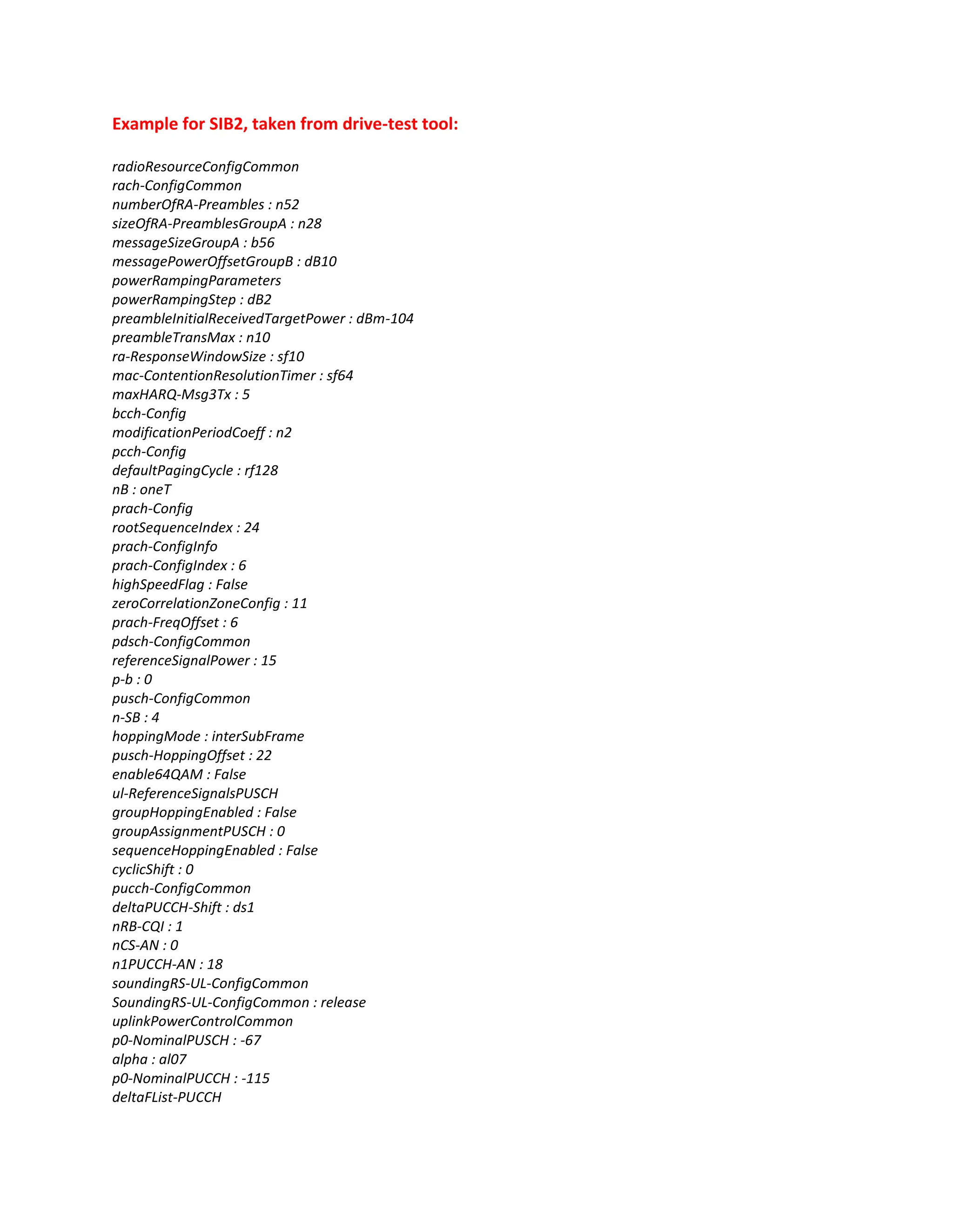
System Information BlockType 2 or with shortened version SIB2 contains radio resource
configuration information that is common for all UEs, including Access Class Barring
configuration, RACH related configuration, Timers, UL Power control, Sounding Reference
Signal configuration and etc. SIB2 is transmitted from the network to UE through BCCH -> DL-
SCH -> PDSCH channels.
Here the list of carried information from the network to UE through SIB2:
AC-Barring For Emergency: the emergency call barring status of access class 10, indicating
whether UEs of access class 10 can initiate emergency calls or not.
AC-Barring For MO-Signaling: access barring information for signaling.
ac-Barring Factor: indicates the access probability factor for signaling.
ac-Barring Time: indicates the average access barring duration for signaling.
ac-Barring For Special AC: “false” or ”true”. Signaling is applied for special Access classes (CSFB,
VoLTE etc.).
AC-Barring for MO-Data: access barring information for mobile-originated calls.
ac-Barring Factor: indicates the access probability factor for mobile-originated calls.
ac-Barring Time: indicates the average access barring duration for mobile-originated calls.
ac-Barring For Special AC: “false” or ”true”. Mobile-originated call is applied for special Access
classes (CSFB, VoLTE etc.).
RACH Config Common: contains parameters related to RACH configuration at the MAC level
across the cell.
Number Of RA-Preambles: number of non-dedicated random access preambles.
Size Of RA-Preambles GroupA: number of non-dedicated random access preambles in Random
Acces Preambles group A.
Message Size GroupA: threshold for determining the size of message when a UE selects a
preamble from random access preamble group A during a random access procedure.
Message Power Offset GroupB: power offset for selection preambles from Group B.
Power Ramping Parameters: indicates the steps for UE power where random access preambles
is increased each time after a RACH access failure.
Power Ramping Step: if multiple attempts to access the PRACH fail, the UE increases power for
random access preambles by a step specified by this parameter.
Preamble Initial Received Target Power: initial UE transmit power for the PRACH which is
expected by the eNodeB.
Preamble Trans Max: maximum number of preamble transmission to achieve success.
RA Response Window Size: duration of RA response window.
MAC Contention Resolution Timer: time when a UE waits for Msg4 during a random access
procedure. This timer starts when a UE initially sends or resends Msg3.
Max HARQ Msg3 Tx: Maximum number of Msg3 HARQ transmissions.
BCCH Config: configuration information of the Broadcast Control Channel.
Modification Period Coeff: modification period coefficient for the BCCH. BCCH modification
period is equal to Modification period coefficient multiplies default DRX cycle.
6.
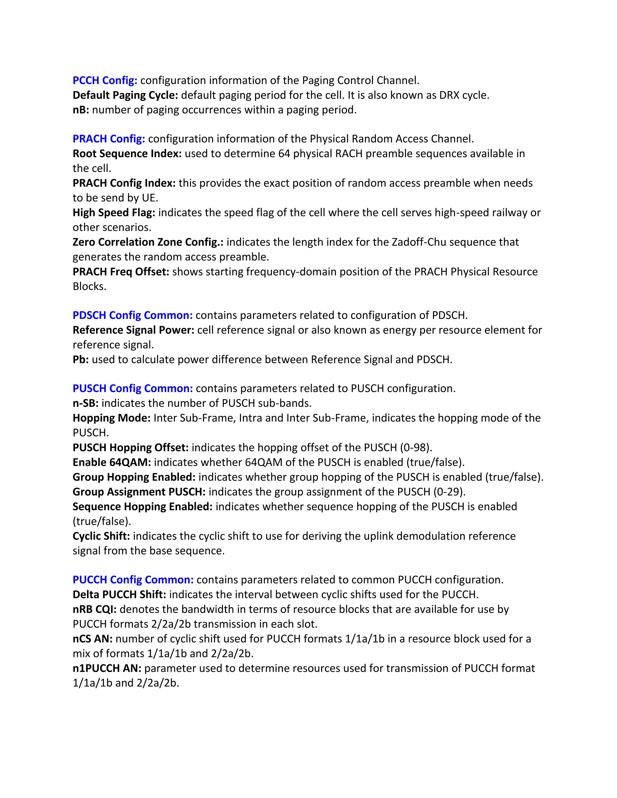
PCCH Config: configurationinformation of the Paging Control Channel.
Default Paging Cycle: default paging period for the cell. It is also known as DRX cycle.
nB: number of paging occurrences within a paging period.
PRACH Config: configuration information of the Physical Random Access Channel.
Root Sequence Index: used to determine 64 physical RACH preamble sequences available in
the cell.
PRACH Config Index: this provides the exact position of random access preamble when needs
to be send by UE.
High Speed Flag: indicates the speed flag of the cell where the cell serves high-speed railway or
other scenarios.
Zero Correlation Zone Config.: indicates the length index for the Zadoff-Chu sequence that
generates the random access preamble.
PRACH Freq Offset: shows starting frequency-domain position of the PRACH Physical Resource
Blocks.
PDSCH Config Common: contains parameters related to configuration of PDSCH.
Reference Signal Power: cell reference signal or also known as energy per resource element for
reference signal.
Pb: used to calculate power difference between Reference Signal and PDSCH.
PUSCH Config Common: contains parameters related to PUSCH configuration.
n-SB: indicates the number of PUSCH sub-bands.
Hopping Mode: Inter Sub-Frame, Intra and Inter Sub-Frame, indicates the hopping mode of the
PUSCH.
PUSCH Hopping Offset: indicates the hopping offset of the PUSCH (0-98).
Enable 64QAM: indicates whether 64QAM of the PUSCH is enabled (true/false).
Group Hopping Enabled: indicates whether group hopping of the PUSCH is enabled (true/false).
Group Assignment PUSCH: indicates the group assignment of the PUSCH (0-29).
Sequence Hopping Enabled: indicates whether sequence hopping of the PUSCH is enabled
(true/false).
Cyclic Shift: indicates the cyclic shift to use for deriving the uplink demodulation reference
signal from the base sequence.
PUCCH Config Common: contains parameters related to common PUCCH configuration.
Delta PUCCH Shift: indicates the interval between cyclic shifts used for the PUCCH.
nRB CQI: denotes the bandwidth in terms of resource blocks that are available for use by
PUCCH formats 2/2a/2b transmission in each slot.
nCS AN: number of cyclic shift used for PUCCH formats 1/1a/1b in a resource block used for a
mix of formats 1/1a/1b and 2/2a/2b.
n1PUCCH AN: parameter used to determine resources used for transmission of PUCCH format
1/1a/1b and 2/2a/2b.
7.
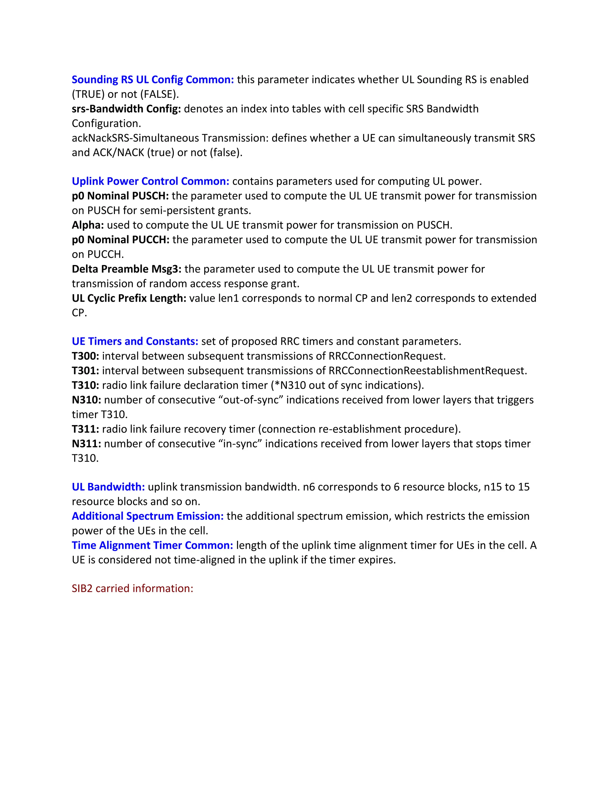
Sounding RS ULConfig Common: this parameter indicates whether UL Sounding RS is enabled
(TRUE) or not (FALSE).
srs-Bandwidth Config: denotes an index into tables with cell specific SRS Bandwidth
Configuration.
ackNackSRS-Simultaneous Transmission: defines whether a UE can simultaneously transmit SRS
and ACK/NACK (true) or not (false).
Uplink Power Control Common: contains parameters used for computing UL power.
p0 Nominal PUSCH: the parameter used to compute the UL UE transmit power for transmission
on PUSCH for semi-persistent grants.
Alpha: used to compute the UL UE transmit power for transmission on PUSCH.
p0 Nominal PUCCH: the parameter used to compute the UL UE transmit power for transmission
on PUCCH.
Delta Preamble Msg3: the parameter used to compute the UL UE transmit power for
transmission of random access response grant.
UL Cyclic Prefix Length: value len1 corresponds to normal CP and len2 corresponds to extended
CP.
UE Timers and Constants: set of proposed RRC timers and constant parameters.
T300: interval between subsequent transmissions of RRCConnectionRequest.
T301: interval between subsequent transmissions of RRCConnectionReestablishmentRequest.
T310: radio link failure declaration timer (*N310 out of sync indications).
N310: number of consecutive “out-of-sync” indications received from lower layers that triggers
timer T310.
T311: radio link failure recovery timer (connection re-establishment procedure).
N311: number of consecutive “in-sync” indications received from lower layers that stops timer
T310.
UL Bandwidth: uplink transmission bandwidth. n6 corresponds to 6 resource blocks, n15 to 15
resource blocks and so on.
Additional Spectrum Emission: the additional spectrum emission, which restricts the emission
power of the UEs in the cell.
Time Alignment Timer Common: length of the uplink time alignment timer for UEs in the cell. A
UE is considered not time-aligned in the uplink if the timer expires.
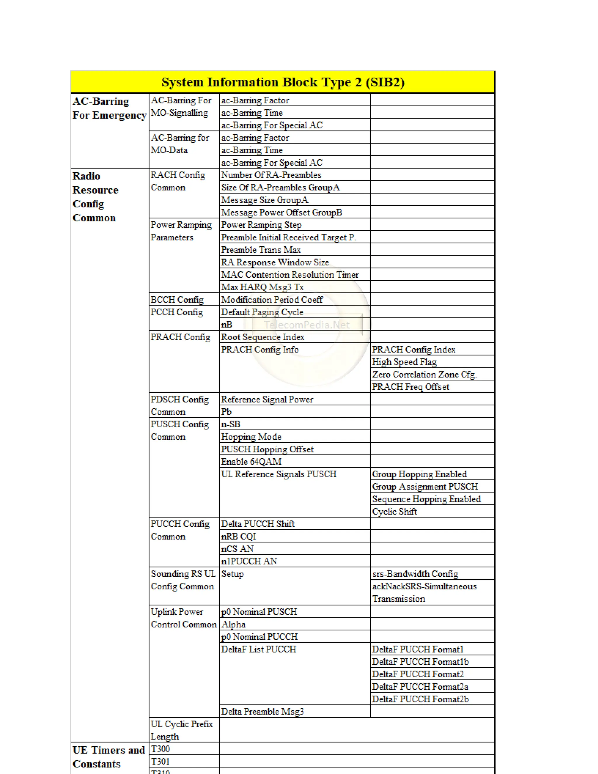
SIB2 carried information:
deltaF-PUCCH-Format1 : deltaF0
deltaF-PUCCH-Format1b: deltaF3
deltaF-PUCCH-Format2 : deltaF1
deltaF-PUCCH-Format2a : deltaF2
deltaF-PUCCH-Format2b : deltaF2
deltaPreambleMsg3 : 4
ul-CyclicPrefixLength : len1
ue-TimersAndConstants
t300 : ms1000
t301 : ms200
t310 : ms1000
n310 : n10
t311 : ms10000
n311 : n1
ul-Bandwidth : n75
additionalSpectrumEmission : 1
timeAlignmentTimerCommon : infinity
* Note: there are some parameters which might not be seen in the message list from drive-test
tool, so it means this parameter was not configured in the network by the engineers.
SIB3
11.
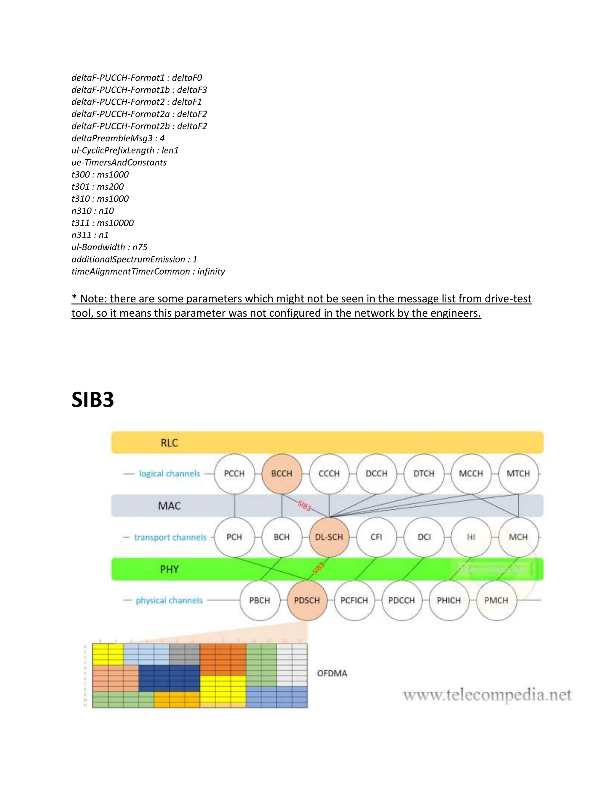
System Information BlockType 3 or with shortened version SIB3 contains common information
for Intra-Frequency, Inter-Frequency and Inter-Technology cell re-selection parameters. But
these parameter values are not applied in all re-selection scenarios. SIB3 is transmitted from
the network to UE through BCCH -> DL-SCH -> PDSCH channels.
Here the list of carried information from the network to UE through SIB3:
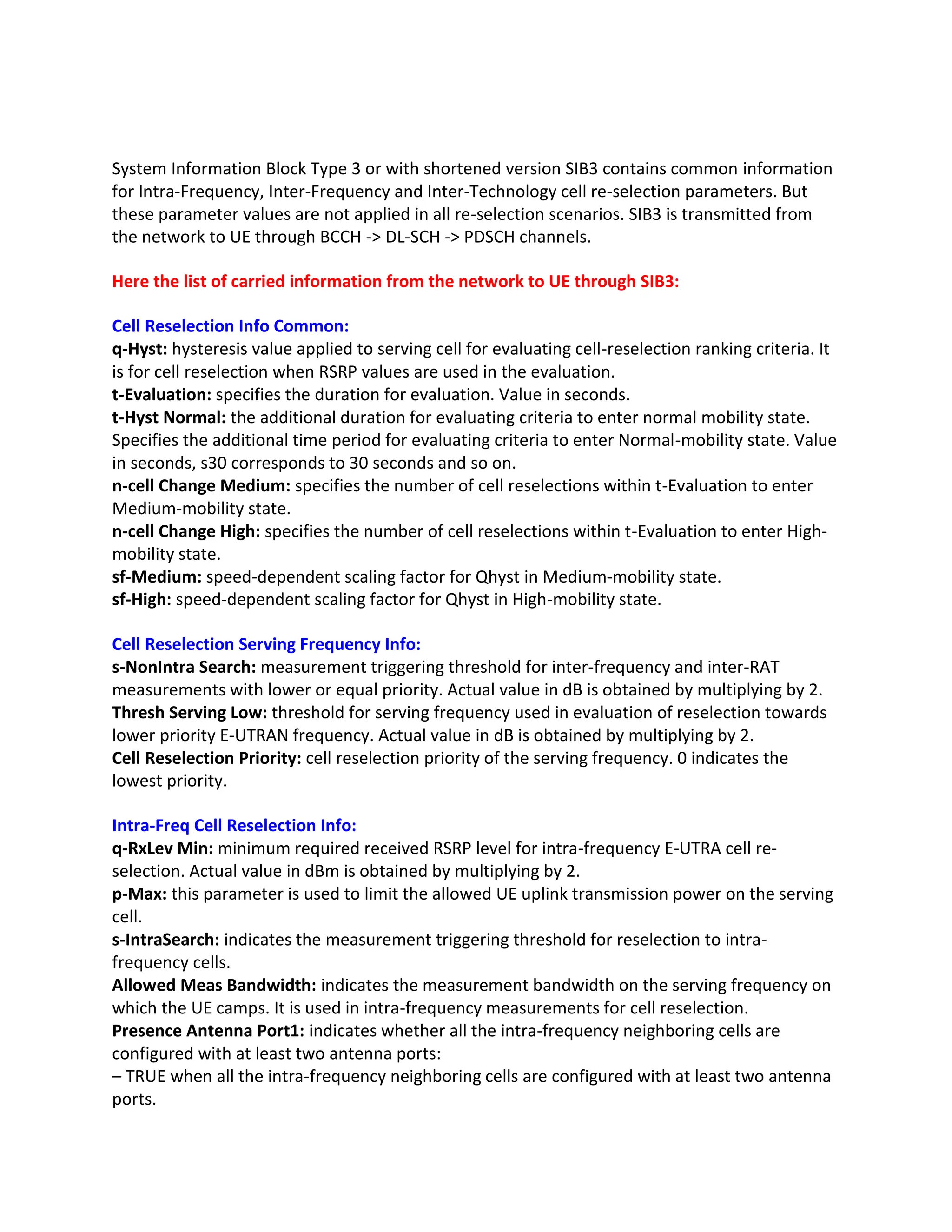
Cell Reselection Info Common:
q-Hyst: hysteresis value applied to serving cell for evaluating cell-reselection ranking criteria. It
is for cell reselection when RSRP values are used in the evaluation.
t-Evaluation: specifies the duration for evaluation. Value in seconds.
t-Hyst Normal: the additional duration for evaluating criteria to enter normal mobility state.
Specifies the additional time period for evaluating criteria to enter Normal-mobility state. Value
in seconds, s30 corresponds to 30 seconds and so on.
n-cell Change Medium: specifies the number of cell reselections within t-Evaluation to enter
Medium-mobility state.
n-cell Change High: specifies the number of cell reselections within t-Evaluation to enter High-
mobility state.
sf-Medium: speed-dependent scaling factor for Qhyst in Medium-mobility state.
sf-High: speed-dependent scaling factor for Qhyst in High-mobility state.
Cell Reselection Serving Frequency Info:
s-NonIntra Search: measurement triggering threshold for inter-frequency and inter-RAT
measurements with lower or equal priority. Actual value in dB is obtained by multiplying by 2.
Thresh Serving Low: threshold for serving frequency used in evaluation of reselection towards
lower priority E-UTRAN frequency. Actual value in dB is obtained by multiplying by 2.
Cell Reselection Priority: cell reselection priority of the serving frequency. 0 indicates the
lowest priority.
Intra-Freq Cell Reselection Info:
q-RxLev Min: minimum required received RSRP level for intra-frequency E-UTRA cell re-
selection. Actual value in dBm is obtained by multiplying by 2.
p-Max: this parameter is used to limit the allowed UE uplink transmission power on the serving
cell.
s-IntraSearch: indicates the measurement triggering threshold for reselection to intra-
frequency cells.
Allowed Meas Bandwidth: indicates the measurement bandwidth on the serving frequency on
which the UE camps. It is used in intra-frequency measurements for cell reselection.
Presence Antenna Port1: indicates whether all the intra-frequency neighboring cells are
configured with at least two antenna ports:
– TRUE when all the intra-frequency neighboring cells are configured with at least two antenna
ports.
12.
– FALSE whenone of the intra-frequency neighboring cells is configured with only one antenna
port.
Neigh Cell Config: provides the information related to MBSFN and TDD UL/DL configuration of
neighbor cells:
– “00” some neighboring cells have the same MBSFN sub-frame configuration as the serving
cell.
– “01” none of the neighboring cells is configured with MBSFN sub-frames.
– “10” MBSFN sub-frame configurations of all neighboring cells are the same as the serving cell.
– “11” some neighboring cells have different UL-DL configurations from the serving TDD cell.
t-Reselection EUTRA: cell reselection timer for intra frequency E-UTRA cell reselection. Value in
seconds.
sf-Medium: specifies scaling factor for intra-frequency t-Reselection EUTRA in Medium-mobility
state. Value oDot25 corresponds to 0.25, oDot5 corresponds to 0.5 etc.
sf-High: specifies scaling factor for intra-frequency t-Reselection EUTRA in High-mobility state.
Value oDot25 corresponds to 0.25, oDot5 corresponds to 0.5 etc.
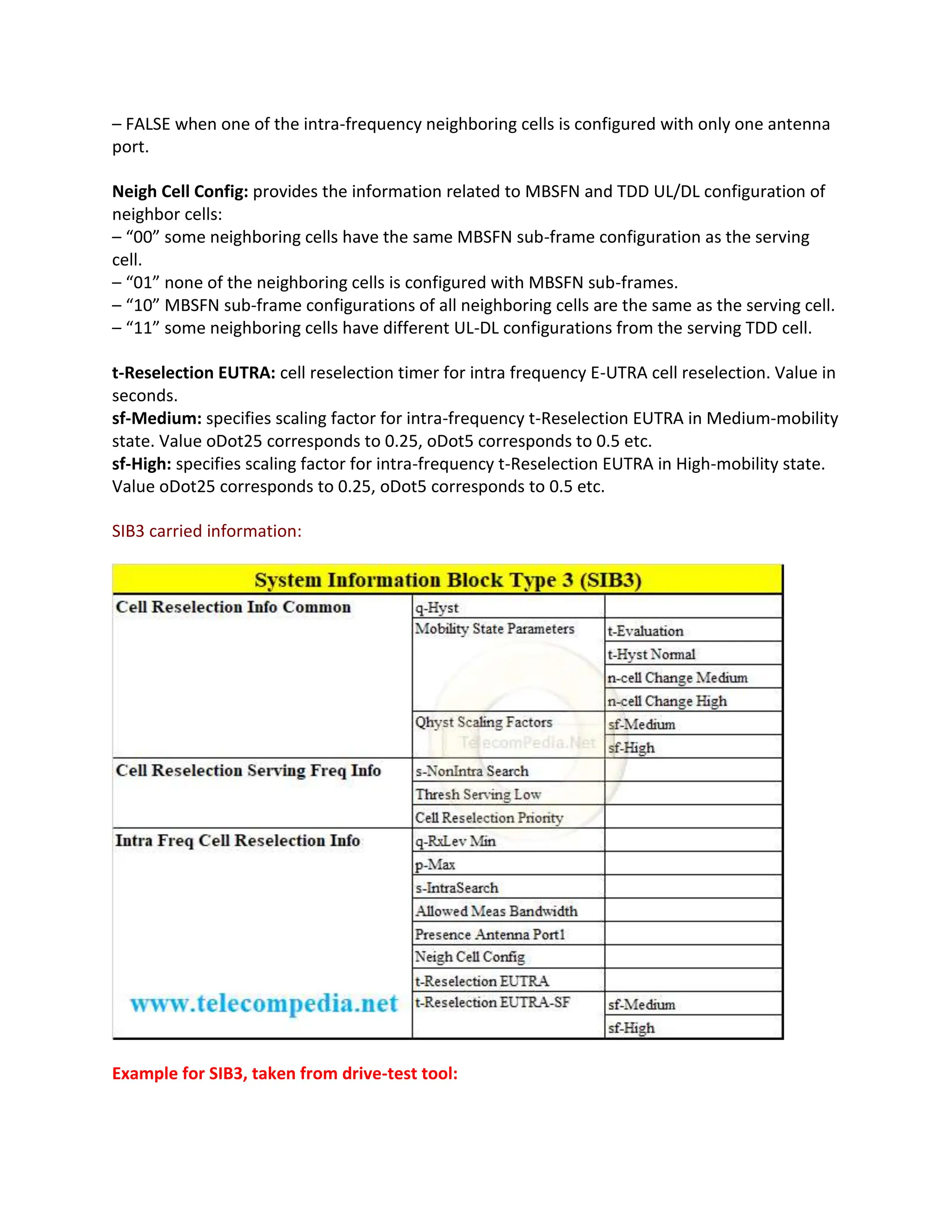
SIB3 carried information:
Example for SIB3, taken from drive-test tool:
13.
System Information Block3
q-Hyst : dB4
s-NonIntraSearch : 2
threshServingLow : 1
cellReselectionPriority : 5
q-RxLevMin : -60
p-Max : 23
s-IntraSearch : 31
presenceAntennaPort1 : False
neighCellConfig
Binary string (Bin) : 01
[0 ] : 0
[1 ] : 1
t-ReselectionEUTRA : 1
t-ReselectionEUTRA-SF
sf-Medium : lDot0
sf-High : oDot75
* Note: there are some parameters which might not be seen in the message list from drive-test
tool, so it means this parameter was not configured in the network by the engineers.
SIB4
14.
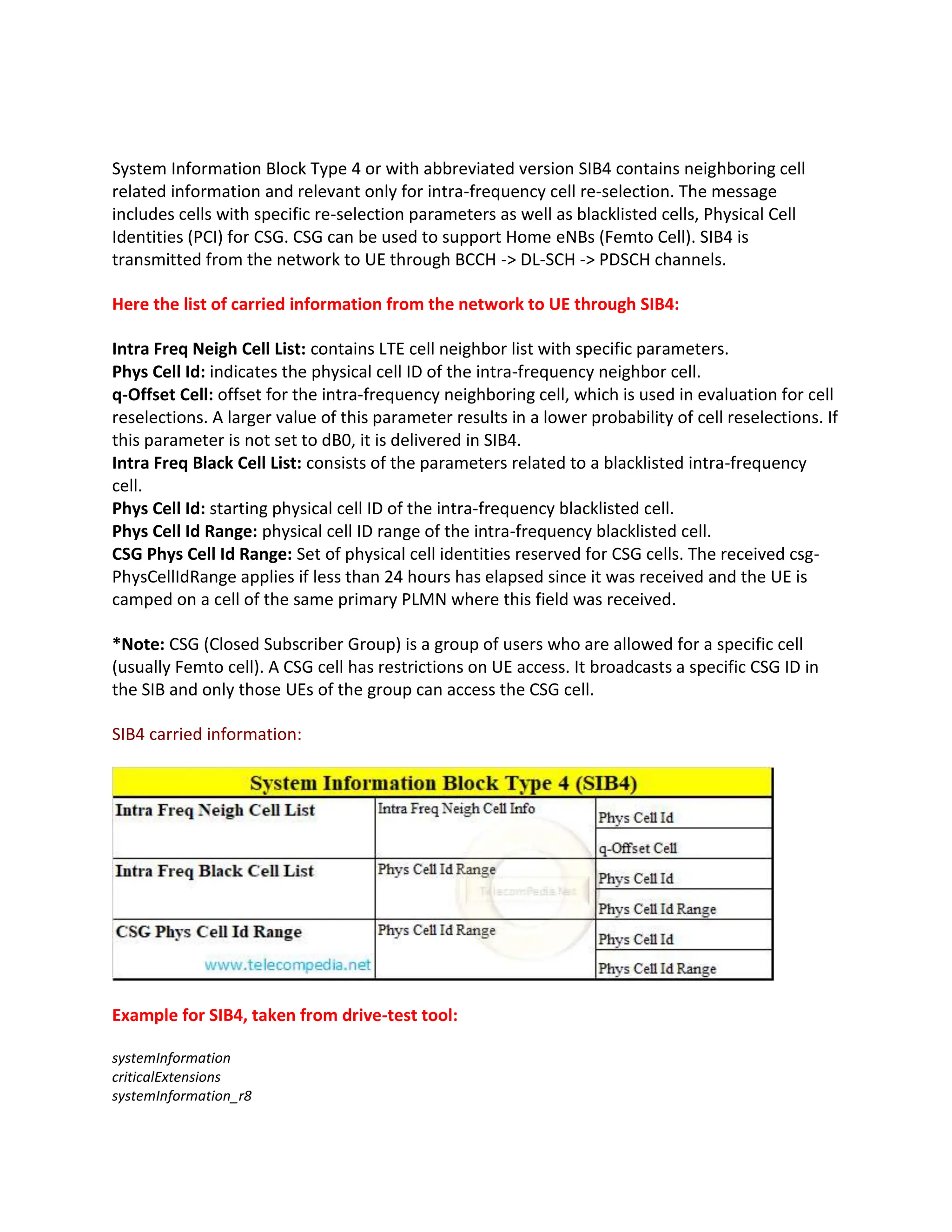
System Information BlockType 4 or with abbreviated version SIB4 contains neighboring cell
related information and relevant only for intra-frequency cell re-selection. The message
includes cells with specific re-selection parameters as well as blacklisted cells, Physical Cell
Identities (PCI) for CSG. CSG can be used to support Home eNBs (Femto Cell). SIB4 is
transmitted from the network to UE through BCCH -> DL-SCH -> PDSCH channels.
Here the list of carried information from the network to UE through SIB4:
Intra Freq Neigh Cell List: contains LTE cell neighbor list with specific parameters.
Phys Cell Id: indicates the physical cell ID of the intra-frequency neighbor cell.
q-Offset Cell: offset for the intra-frequency neighboring cell, which is used in evaluation for cell
reselections. A larger value of this parameter results in a lower probability of cell reselections. If
this parameter is not set to dB0, it is delivered in SIB4.
Intra Freq Black Cell List: consists of the parameters related to a blacklisted intra-frequency
cell.
Phys Cell Id: starting physical cell ID of the intra-frequency blacklisted cell.
Phys Cell Id Range: physical cell ID range of the intra-frequency blacklisted cell.
CSG Phys Cell Id Range: Set of physical cell identities reserved for CSG cells. The received csg-
PhysCellIdRange applies if less than 24 hours has elapsed since it was received and the UE is
camped on a cell of the same primary PLMN where this field was received.
*Note: CSG (Closed Subscriber Group) is a group of users who are allowed for a specific cell
(usually Femto cell). A CSG cell has restrictions on UE access. It broadcasts a specific CSG ID in
the SIB and only those UEs of the group can access the CSG cell.
SIB4 carried information:
Example for SIB4, taken from drive-test tool:
systemInformation
criticalExtensions
systemInformation_r8
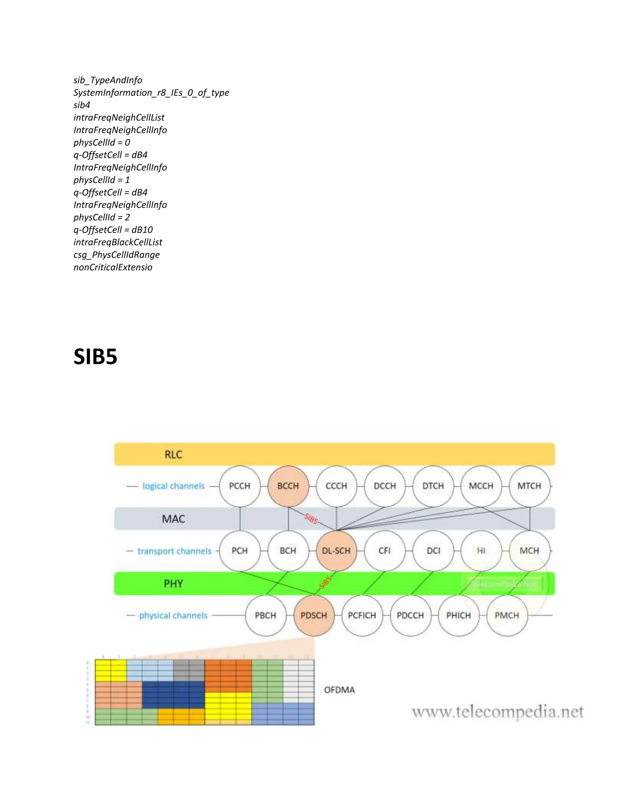
System Information BlockType 5 or with abbreviated version SIB5 contains EUTRAN frequency
related information and relevant only for inter-frequency cell re-selection. The message
includes frequencies with specific re-selection parameters as well as blacklisted cells. SIB5 is
transmitted from the network to UE through BCCH -> DL-SCH -> PDSCH channels.
Here the list of carried information from the network to UE through SIB5:
Inter Freq Carrier Freq List: contains information about inter-frequency cell re-selection within
E-UTRAN.
dl-Carrier Freq: indicates target frequency EARFCN for inter-frequency cell re-selection.
q-RxLev Min: required minimum received RSRP level on this E-UTRA frequency carrier. Actual
value in dBm is obtained by multiplying by 2.
p-Max: this parameter is used to limit the allowed UE uplink transmission power on this carrier
frequency.
t-Reselection EUTRA: cell reselection timer for inter-frequency cell reselection to this E-UTRA
frequency carrier.
sf-Medium: specifies scaling factor for t-Reselection EUTRA for inter-frequency reselection to
this frequency carrier in Medium-mobility state. Value oDot25 corresponds to 0.25, oDot5
corresponds to 0.5 etc.
sf-High: specifies scaling factor for t-Reselection EUTRA for inter-frequency reselection to this
frequency carrier in High-mobility state. Value oDot25 corresponds to 0.25, oDot5 corresponds
to 0.5 etc.
threshX-High: inter frequency high priority threshold, the threshold used when reselecting
from a lower priority LTE frequency to higher priority LTE frequency. Actual value in dB is
obtained by multiplying by 2.
threshX-Low: inter frequency lower priority threshold, the threshold used when reselecting
from a higher priority LTE frequency to lower priority LTE frequency. Actual value in dB is
obtained by multiplying by 2.
Allowed Meas Bandwidth: indicates the measurement bandwidth of the inter-frequency
neighboring cell on the frequency. A cell bandwidth is also expressed in units of physical
resource blocks. Cell bandwidths 1.4 MHz, 3 MHz, 5 MHz, 10 MHz, 15 MHz, and 20 MHz
correspond to 6 RBs, 15 RBs, 25 RBs, 50 RBs, 75 RBs, and 100 RBs.
Presence Antenna Port1: indicates whether all the inter-frequency neighboring cells are
configured with at least two antenna ports:
– TRUE when all the inter-frequency neighboring cells are configured with at least two antenna
ports.
– FALSE when one of the inter-frequency neighboring cells is configured with only one antenna
port.
17.
Cell Reselection Priority:inter-frequency cell re-selection priority indicates priority of the
neighboring E-UTRAN frequency. The value 0 indicates the lowest priority.
Neigh Cell Config: provides the information related to MBSFN and TDD UL/DL configuration of
inter-frequency neighbor cells:
– “00” inter-frequency neighboring cells have the same MBSFN sub-frame configuration as the
serving cell.
– “01” none of the inter-frequency neighboring cells is configured with MBSFN sub-frames.
– “10” MBSFN sub-frame configurations of all inter-frequency neighboring cells are ame as the
serving cell.
– “11” some inter-frequency neighboring cells have different UL-DL configurations from serving
TDD cell.
q-Offset Freq: offset applicable between serving and this frequency carrier. Actual value in dBm
is obtained by multiplying by 2. A larger value of this parameter results in a lower probability of
reselection to cells on the neighboring E-UTRAN frequency. A smaller value of this parameter
leads to the opposite effects.
Inter Freq Black Cell List: consists of the parameters related to a blacklisted inter-frequency
cell.
Phys Cell Id: starting physical cell ID of the inter-frequency blacklisted cell.
Phys Cell Id Range: physical cell ID range of the inter-frequency blacklisted cell.
SIB5 carried information:
Example for SIB5, taken from drive-test tool:
interFreqCarrierFreqList
InterFreqCarrierFreqList :
[0 ] :
dl-CarrierFreq : 1524
q-RxLevMin : -60
18.
p-Max : 23
t-ReselectionEUTRA: 1
threshX-High : 11
threshX-Low : 2
allowedMeasBandwidth : mbw75
presenceAntennaPort1 : False
cellReselectionPriority : 5
neighCellConfig
Binary string (Bin) : 01
[0 ] : 0
[1 ] : 1
[1 ] :
dl-CarrierFreq : 1475
q-RxLevMin : -60
p-Max : 23
t-ReselectionEUTRA : 1
threshX-High : 11
threshX-Low : 11
allowedMeasBandwidth : mbw50
presenceAntennaPort1 : False
cellReselectionPriority : 3
neighCellConfig
Binary string (Bin) : 01
[0 ] : 0
[1 ] : 1
* Note: there are some parameters which might not be seen in the message list from drive-test
tool, so it means this parameter was not configured in the network by the engineers.
SIB6
19.
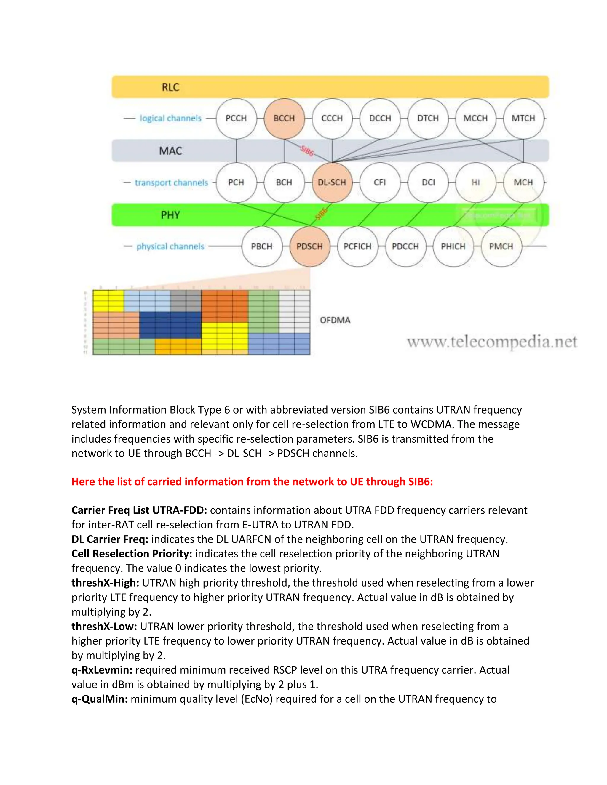
System Information BlockType 6 or with abbreviated version SIB6 contains UTRAN frequency
related information and relevant only for cell re-selection from LTE to WCDMA. The message
includes frequencies with specific re-selection parameters. SIB6 is transmitted from the
network to UE through BCCH -> DL-SCH -> PDSCH channels.
Here the list of carried information from the network to UE through SIB6:
Carrier Freq List UTRA-FDD: contains information about UTRA FDD frequency carriers relevant
for inter-RAT cell re-selection from E-UTRA to UTRAN FDD.
DL Carrier Freq: indicates the DL UARFCN of the neighboring cell on the UTRAN frequency.
Cell Reselection Priority: indicates the cell reselection priority of the neighboring UTRAN
frequency. The value 0 indicates the lowest priority.
threshX-High: UTRAN high priority threshold, the threshold used when reselecting from a lower
priority LTE frequency to higher priority UTRAN frequency. Actual value in dB is obtained by
multiplying by 2.
threshX-Low: UTRAN lower priority threshold, the threshold used when reselecting from a
higher priority LTE frequency to lower priority UTRAN frequency. Actual value in dB is obtained
by multiplying by 2.
q-RxLevmin: required minimum received RSCP level on this UTRA frequency carrier. Actual
value in dBm is obtained by multiplying by 2 plus 1.
q-QualMin: minimum quality level (EcNo) required for a cell on the UTRAN frequency to
20.
become a candidatefor reselection.
p-MaxUTRA: this parameter is used to limit the allowed UE uplink transmission power on this
UTRA FDD carrier frequency.
t-ReselectionUTRA: indicates the evaluation period for a UE to determine whether to reselect a
neighboring UTRAN cell to camp on.
sf-Medium: specifies scaling factor for t-ReselectionUTRA for inter-RAT reselection to UTRA in
Medium-mobility state. Value oDot25 corresponds to 0.25, oDot5 corresponds to 0.5 etc.
sf-High: specifies scaling factor for t-ReselectionUTRA for inter-RAT reselection to UTRA in High-
mobility state. Value oDot25 corresponds to 0.25, oDot5 corresponds to 0.5 etc.
SIB6 carried information:
Example for SIB6, taken from drive-test tool:
systemInformation[0]BCCH-DLSCH-Message=
message = c1 = systemInformation =
criticalExtensions = systemInformation-r8 =
sib-TypeAndInfo = SEQUENCE OF CHOICE
CHOICE(1) = sib6 =
carrierFreqListUTRA-FDD = SEQUENCE OF
CarrierFreqUTRA-FDD (0) =
carrierFreq = 10787
cellReselectionPriority = 4
threshX-High = 2
threshX-Low = 1
q-RxLevmin = -58
p-MaxUTRA = 24
q-QualMin = -22
CarrierFreqUTRA-FDD (1) =
carrierFreq = 10787
cellReselectionPriority = 3
threshX-High = 6
threshX-Low = 6
21.
q-RxLevmin = -58
p-MaxUTRA= 24
q-QualMin = -18
t-ReselectionUTRA = 1
t-ReselectionUTRA-SF
sf-Medium : lDot0
sf-High : oDot75
* Note: there are some parameters which might not be seen in the message list from drive-test
tool, so it means this parameter was not configured in the network by the engineers.
SIB7
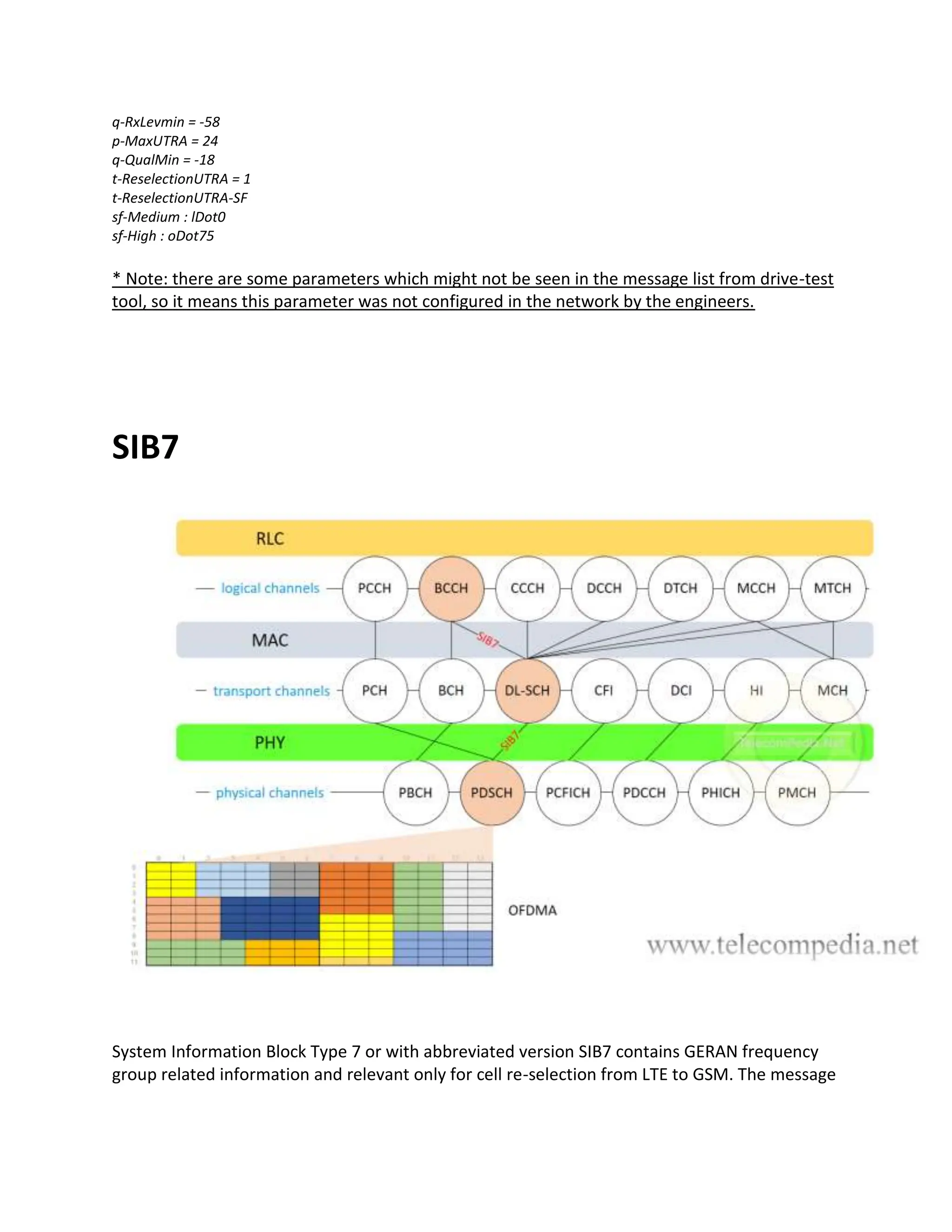
System Information Block Type 7 or with abbreviated version SIB7 contains GERAN frequency
group related information and relevant only for cell re-selection from LTE to GSM. The message
22.
includes frequency groupswith specific re-selection parameters. SIB7 is transmitted from the
network to UE through BCCH -> DL-SCH -> PDSCH channels.
Here the list of carried information from the network to UE through SIB7:
t-Reselection GERAN: cell reselection timer for reselection to a GERAN frequency carrier. Value
in seconds.
sf-Medium: specifies scaling factor for t-Reselection GERAN for inter-RAT reselection to GERAN
in Medium-mobility state. Value oDot25 corresponds to 0.25, oDot5 corresponds to 0.5 etc.
sf-High: specifies scaling factor for t-Reselection GERAN for inter-RAT reselection to GERAN in
High-mobility state. Value oDot25 corresponds to 0.25, oDot5 corresponds to 0.5 etc.
Carrier Freqs Info List GERAN: parameters related to a neighboring GERAN frequency group,
these parameters are used for Inter-Technology reselection from EUTRAN to GERAN. The
parameters might be different set for each frequency group.
Starting ARFCN: specifies first ARFCN in GERAN frequency group.
Band Indicator: specifies GERAN frequency band, either it is GSM1800 or GSM1900.
Explicit List Of ARFCNs: specifies the ARFCN list of the GERAN BCCH.
Cell Reselection Priority: indicates the cell reselection priority of GERAN frequency group. The
value 0 indicates the lowest priority.
NCC-Permitted: field encoded as a bit map, where bit N is set to “0” if a BCCH carrier with NCC
= N-1 is not permitted for monitoring and set to “1” if a BCCH carrier with NCC = N-1 is
permitted for monitoring; N = 1 to 8; bit 1 of the bitmap is the leading bit of the bit string.
q-RxLevMin: required minimum received RSSI level on GERAN frequency carrier for re-selection
from LTE to GSM. Actual value in dBm is value * 2 – 115.
Pmax: this parameter is used to limit the allowed UE uplink transmission power on this GERAN
carrier frequency.
threshX-High: threshold used when reselecting from lower priority LTE frequency to higher
priority GERAN frequency group. Actual value in dB is obtained by multiplying by 2.
threshX-Low: threshold used when reselecting from higher priority LTE frequency to lower
priority GERAN frequency group. Actual value in dB is obtained by multiplying by 2.
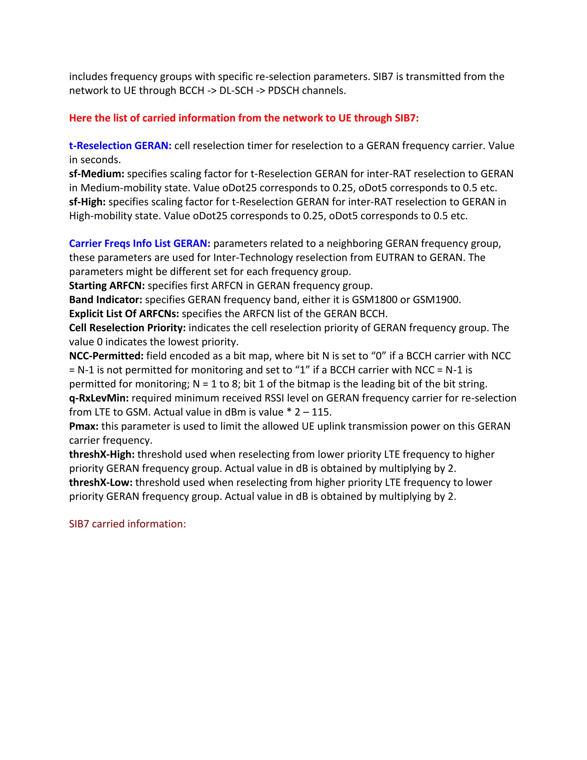
SIB7 carried information:
* Note: thereare some parameters which might not be seen in the message list from drive-test
tool, so it means this parameter was not configured in the network by the engineers.
![Example for SIB1, taken from drive-test tool:
plmn-IdentityList
PLMN-IdentityList :
[0 ] :
plmn-Identity
mcc
MCC :
[0 ] : 1
[1 ] : 1
[2 ] : 1
mnc
MNC :
[0 ] : 0
[1 ] : 2
cellReservedForOperatorUse : notReserved
trackingAreaCode : 38441 (0x9629)
cellIdentity : 113491462 (0x6C3BE06)
cellBarred : notBarred
intraFreqReselection : allowed
csg-Indication : False
q-RxLevMin : -60
p-Max : 23
freqBandIndicator : 3
schedulingInfoList](https://image.slidesharecdn.com/systeminformationblocksinlte-240414070812-1a26fb17/75/SIB-System-Information-Blocks-in-LTE-docx-3-2048.jpg)
![SchedulingInfoList :
[0 ] :
si-Periodicity : rf16
sib-MappingInfo
SIB-MappingInfo :
[0 ] :
extensionBit0 : 0
Optionalitem : sibType3
[1 ] :
si-Periodicity : rf32
sib-MappingInfo
SIB-MappingInfo :
[0 ] :
extensionBit0 : 0
Optionalitem : sibType5
si-WindowLength : ms40
systemInfoValueTag : 8
SIB2](https://image.slidesharecdn.com/systeminformationblocksinlte-240414070812-1a26fb17/75/SIB-System-Information-Blocks-in-LTE-docx-4-2048.jpg)
![System Information Block 3
q-Hyst : dB4
s-NonIntraSearch : 2
threshServingLow : 1
cellReselectionPriority : 5
q-RxLevMin : -60
p-Max : 23
s-IntraSearch : 31
presenceAntennaPort1 : False
neighCellConfig
Binary string (Bin) : 01
[0 ] : 0
[1 ] : 1
t-ReselectionEUTRA : 1
t-ReselectionEUTRA-SF
sf-Medium : lDot0
sf-High : oDot75
* Note: there are some parameters which might not be seen in the message list from drive-test
tool, so it means this parameter was not configured in the network by the engineers.
SIB4](https://image.slidesharecdn.com/systeminformationblocksinlte-240414070812-1a26fb17/75/SIB-System-Information-Blocks-in-LTE-docx-13-2048.jpg)
![Cell Reselection Priority: inter-frequency cell re-selection priority indicates priority of the
neighboring E-UTRAN frequency. The value 0 indicates the lowest priority.
Neigh Cell Config: provides the information related to MBSFN and TDD UL/DL configuration of
inter-frequency neighbor cells:
– “00” inter-frequency neighboring cells have the same MBSFN sub-frame configuration as the
serving cell.
– “01” none of the inter-frequency neighboring cells is configured with MBSFN sub-frames.
– “10” MBSFN sub-frame configurations of all inter-frequency neighboring cells are ame as the
serving cell.
– “11” some inter-frequency neighboring cells have different UL-DL configurations from serving
TDD cell.
q-Offset Freq: offset applicable between serving and this frequency carrier. Actual value in dBm
is obtained by multiplying by 2. A larger value of this parameter results in a lower probability of
reselection to cells on the neighboring E-UTRAN frequency. A smaller value of this parameter
leads to the opposite effects.
Inter Freq Black Cell List: consists of the parameters related to a blacklisted inter-frequency
cell.
Phys Cell Id: starting physical cell ID of the inter-frequency blacklisted cell.
Phys Cell Id Range: physical cell ID range of the inter-frequency blacklisted cell.
SIB5 carried information:
Example for SIB5, taken from drive-test tool:
interFreqCarrierFreqList
InterFreqCarrierFreqList :
[0 ] :
dl-CarrierFreq : 1524
q-RxLevMin : -60](https://image.slidesharecdn.com/systeminformationblocksinlte-240414070812-1a26fb17/75/SIB-System-Information-Blocks-in-LTE-docx-17-2048.jpg)
![p-Max : 23
t-ReselectionEUTRA : 1
threshX-High : 11
threshX-Low : 2
allowedMeasBandwidth : mbw75
presenceAntennaPort1 : False
cellReselectionPriority : 5
neighCellConfig
Binary string (Bin) : 01
[0 ] : 0
[1 ] : 1
[1 ] :
dl-CarrierFreq : 1475
q-RxLevMin : -60
p-Max : 23
t-ReselectionEUTRA : 1
threshX-High : 11
threshX-Low : 11
allowedMeasBandwidth : mbw50
presenceAntennaPort1 : False
cellReselectionPriority : 3
neighCellConfig
Binary string (Bin) : 01
[0 ] : 0
[1 ] : 1
* Note: there are some parameters which might not be seen in the message list from drive-test
tool, so it means this parameter was not configured in the network by the engineers.
SIB6](https://image.slidesharecdn.com/systeminformationblocksinlte-240414070812-1a26fb17/75/SIB-System-Information-Blocks-in-LTE-docx-18-2048.jpg)
![become a candidate for reselection.
p-MaxUTRA: this parameter is used to limit the allowed UE uplink transmission power on this
UTRA FDD carrier frequency.
t-ReselectionUTRA: indicates the evaluation period for a UE to determine whether to reselect a
neighboring UTRAN cell to camp on.
sf-Medium: specifies scaling factor for t-ReselectionUTRA for inter-RAT reselection to UTRA in
Medium-mobility state. Value oDot25 corresponds to 0.25, oDot5 corresponds to 0.5 etc.
sf-High: specifies scaling factor for t-ReselectionUTRA for inter-RAT reselection to UTRA in High-
mobility state. Value oDot25 corresponds to 0.25, oDot5 corresponds to 0.5 etc.
SIB6 carried information:
Example for SIB6, taken from drive-test tool:
systemInformation[0]BCCH-DLSCH-Message=
message = c1 = systemInformation =
criticalExtensions = systemInformation-r8 =
sib-TypeAndInfo = SEQUENCE OF CHOICE
CHOICE(1) = sib6 =
carrierFreqListUTRA-FDD = SEQUENCE OF
CarrierFreqUTRA-FDD (0) =
carrierFreq = 10787
cellReselectionPriority = 4
threshX-High = 2
threshX-Low = 1
q-RxLevmin = -58
p-MaxUTRA = 24
q-QualMin = -22
CarrierFreqUTRA-FDD (1) =
carrierFreq = 10787
cellReselectionPriority = 3
threshX-High = 6
threshX-Low = 6](https://image.slidesharecdn.com/systeminformationblocksinlte-240414070812-1a26fb17/75/SIB-System-Information-Blocks-in-LTE-docx-20-2048.jpg)
![Example for SIB7, taken from drive-test tool:
t-ReselectionGERAN : 1
t-ReselectionUTRA-SF
sf-Medium : lDot0
sf-High : oDot75
carrierFreqsInfoList
CarrierFreqsInfoListGERAN :
[0 ] :
carrierFreqs
startingARFCN : 515
bandIndicator : dcs1800
followingARFCNs :
explicitListOfARFCNs
ExplicitListOfARFCNs :
IntegerType = 520
IntegerType = 525
IntegerType = 530
IntegerType = 580
IntegerType = 585
IntegerType = 800
IntegerType = 855
cellReselectionPriority : 1
ncc-Permitted : 11111111
q-RxLevMin : 2
threshX-High : 7
threshX-Low : 8](https://image.slidesharecdn.com/systeminformationblocksinlte-240414070812-1a26fb17/75/SIB-System-Information-Blocks-in-LTE-docx-23-2048.jpg)