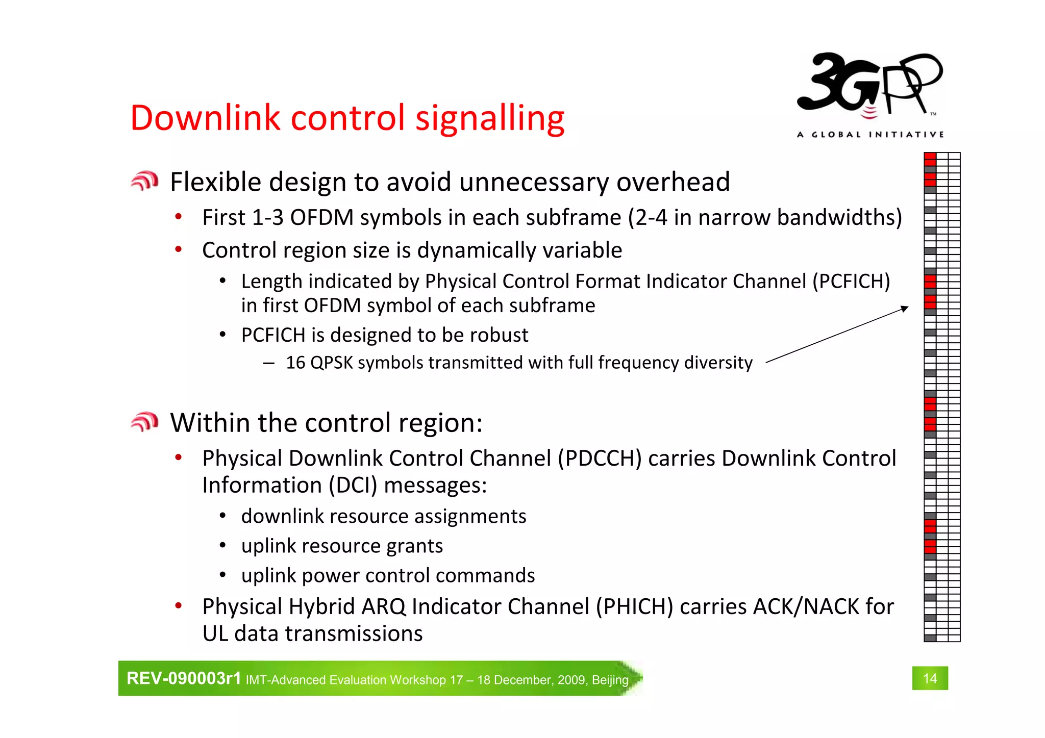
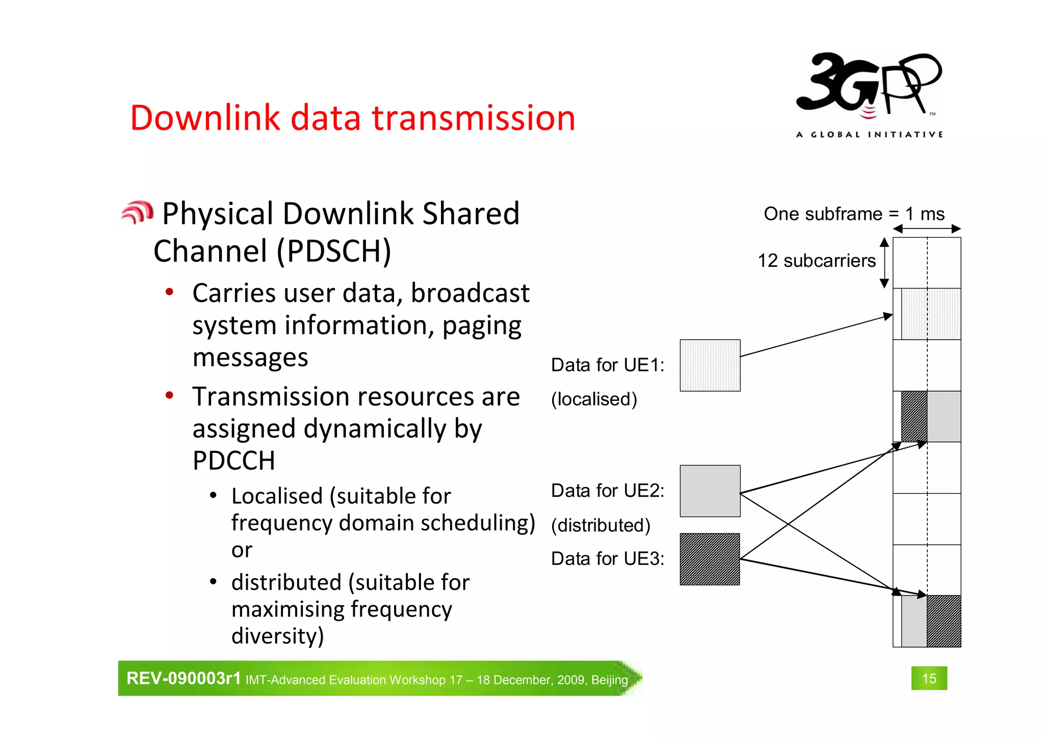
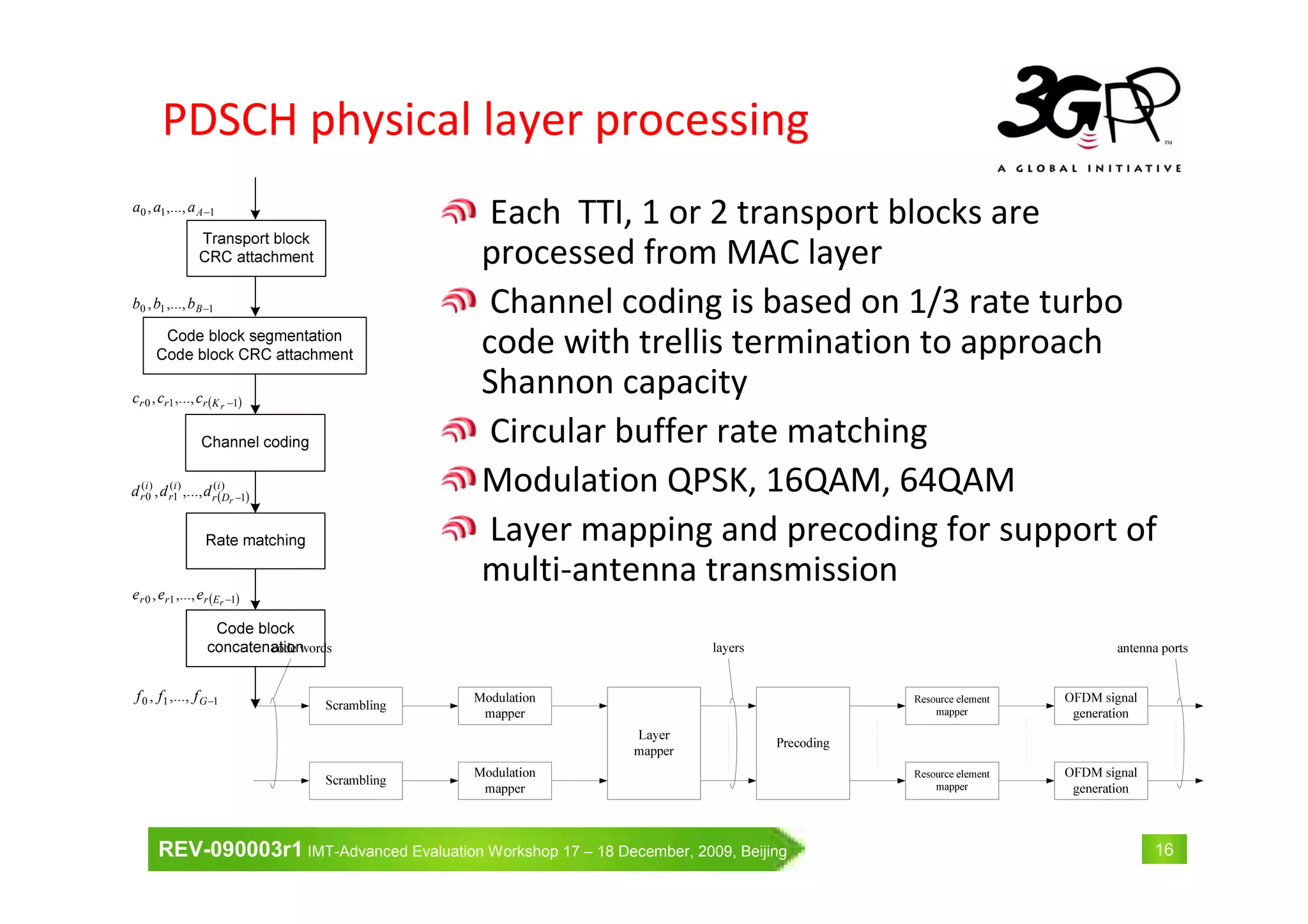
Download as PDF, PPTX
![REV-090003r1 IMT-Advanced Evaluation Workshop 17 – 18 December, 2009, Beijing 39
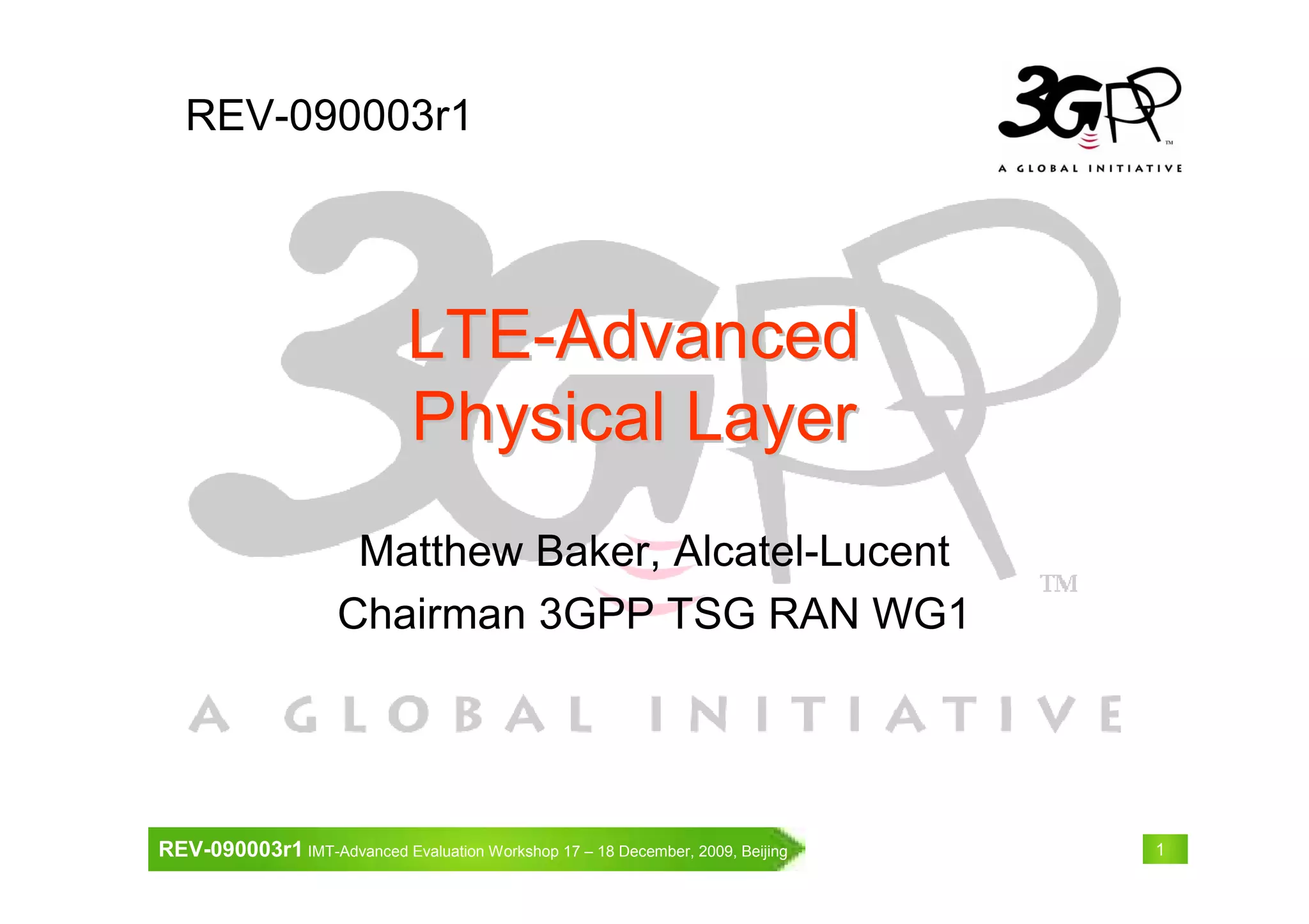
Peak data rate
• 1 Gbps data rate will be achieved by 4-by-4 MIMO and transmission
bandwidth wider than approximately 70 MHz
Peak spectrum efficiency
• DL: Rel. 8 LTE satisfies IMT-Advanced requirement
• UL: Need to double from Release 8 to satisfy IMT-Advanced
requirement
Rel. 8 LTE LTE-Advanced IMT-Advanced
Peak data rate
DL 300 Mbps 1 Gbps
1 Gbps(*)
UL 75 Mbps 500 Mbps
Peak spectrum efficiency
[bps/Hz]
DL 15 30 15
UL 3.75 15 6.75
*“100 Mbps for high mobility and 1 Gbps for low mobility” is one of the key features as written in
Circular Letter (CL)
System Performance Requirements for
LTE-Advanced](https://image.slidesharecdn.com/rev-090003-r1-130814004540-phpapp01/75/LTE-Advanced-Physical-Layer-39-2048.jpg)

This document summarizes the physical layer design of LTE Release 8 and enhancements for LTE-Advanced. It describes the downlink and uplink multiple access schemes, reference signals, control signaling, data transmission procedures, UE categories, and support for frequency division duplex and time division duplex operation. The document provides an overview of the 3GPP release timeline and the specifications that define the LTE physical layer.