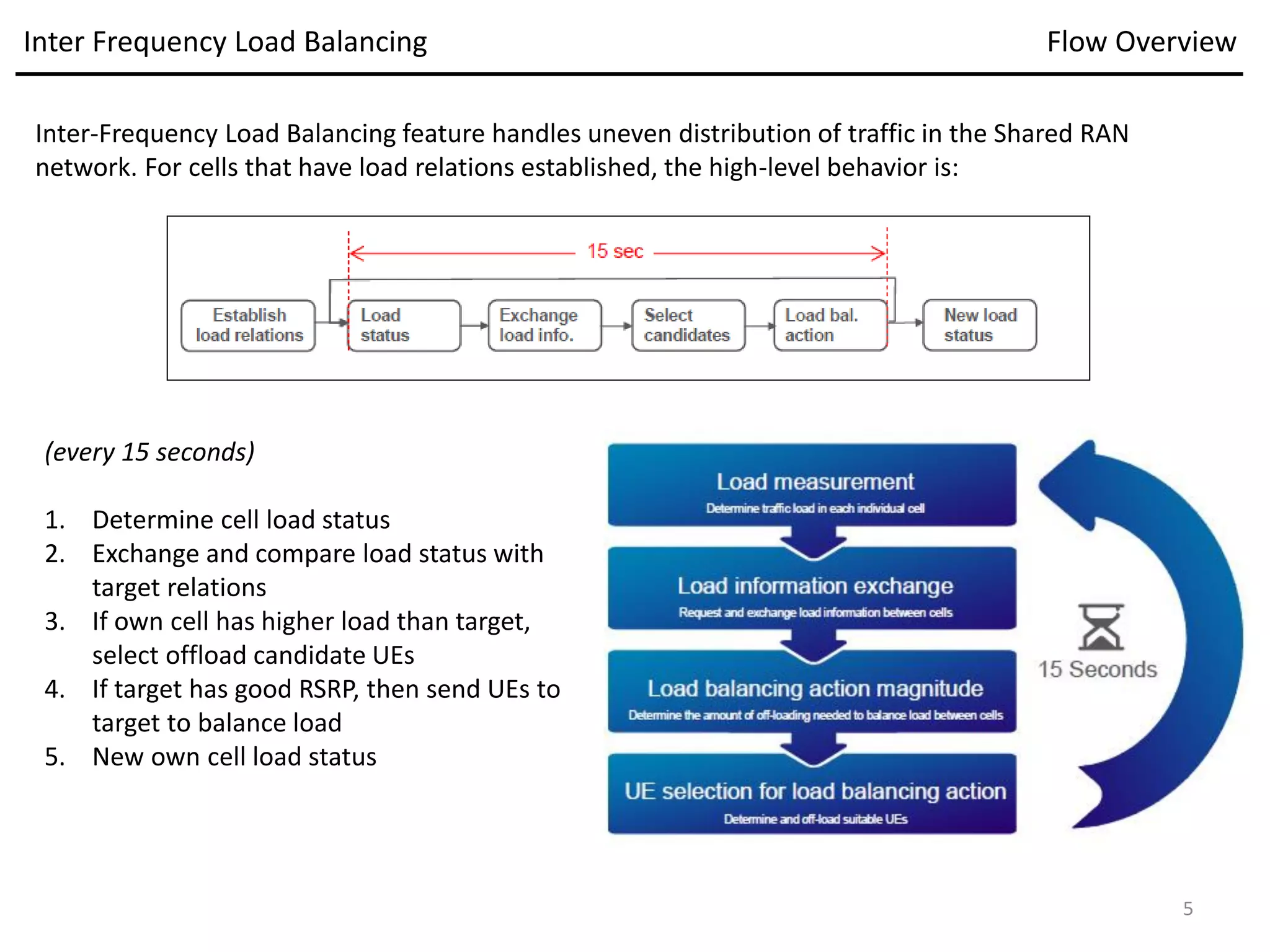
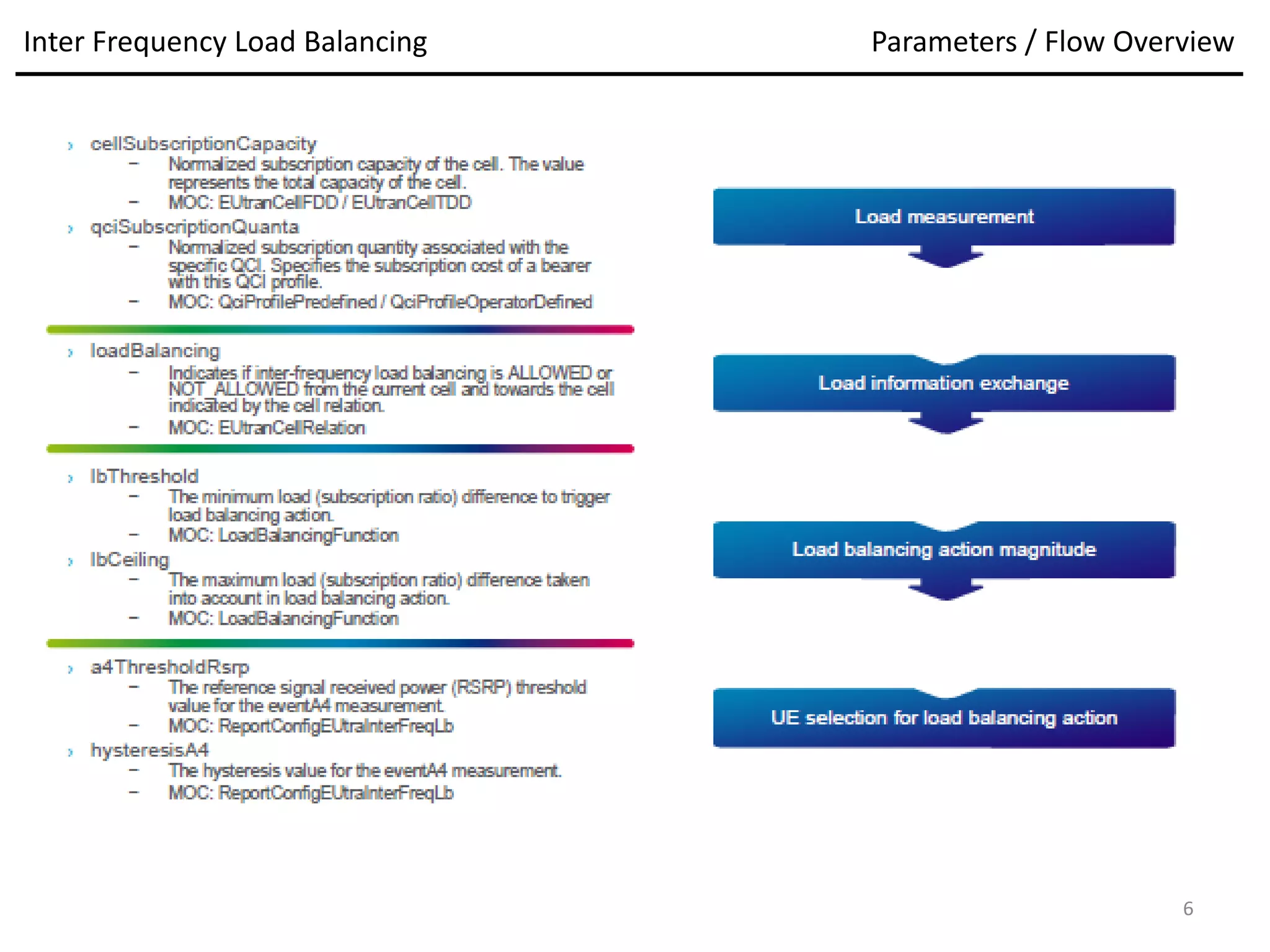
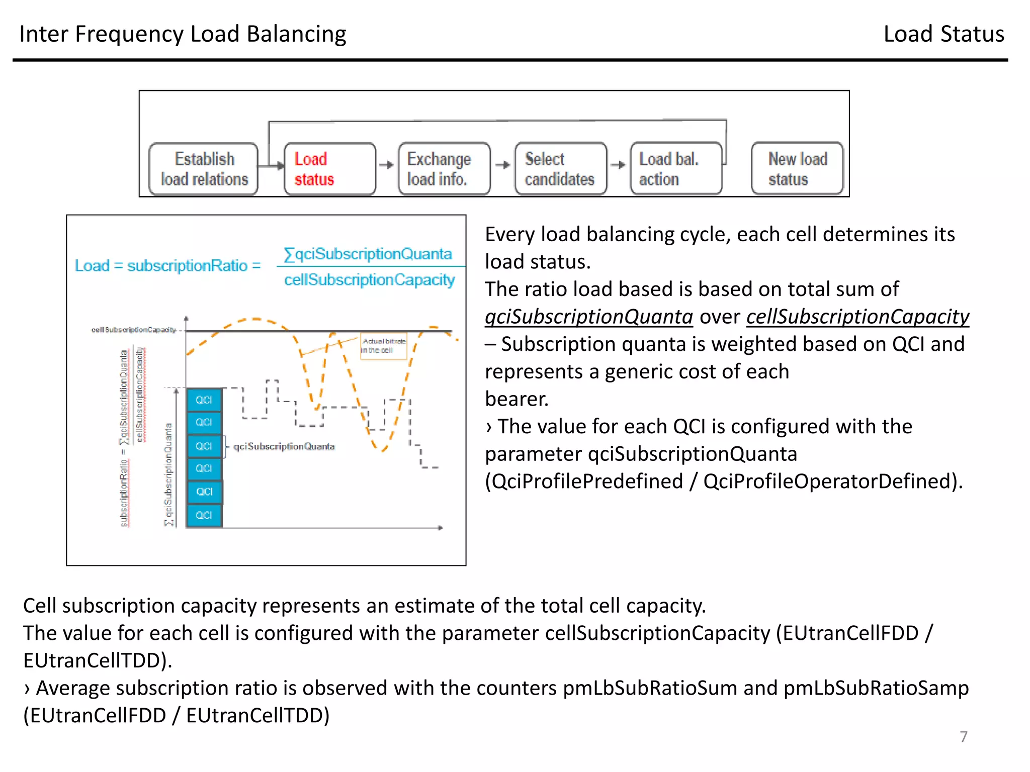
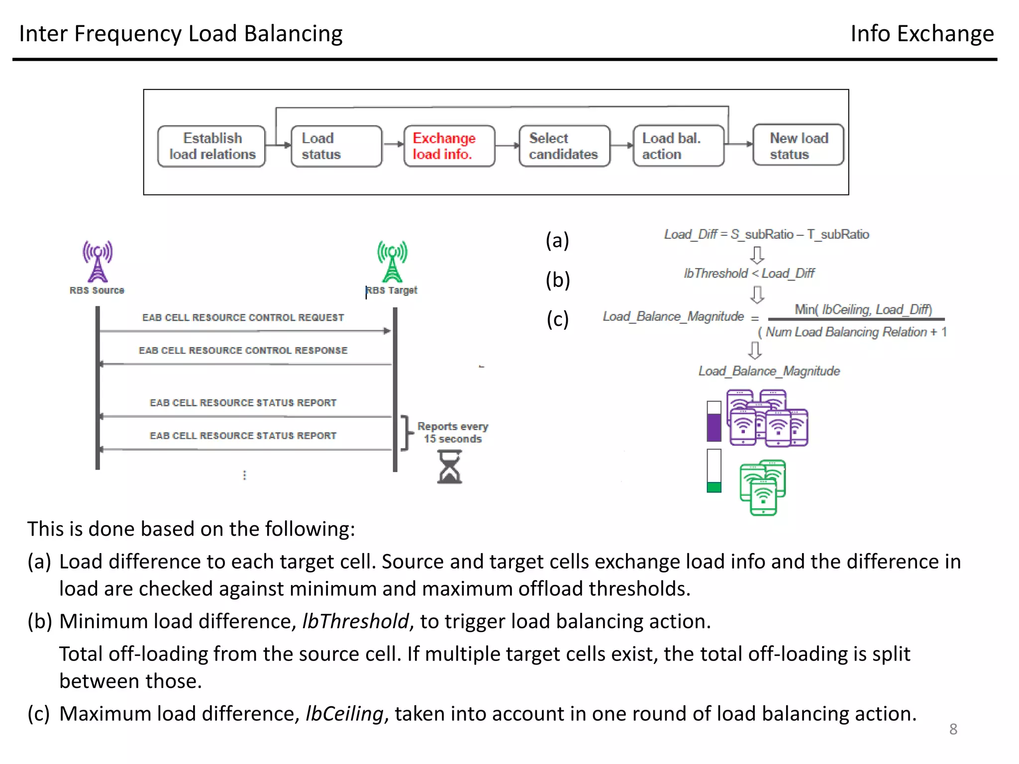
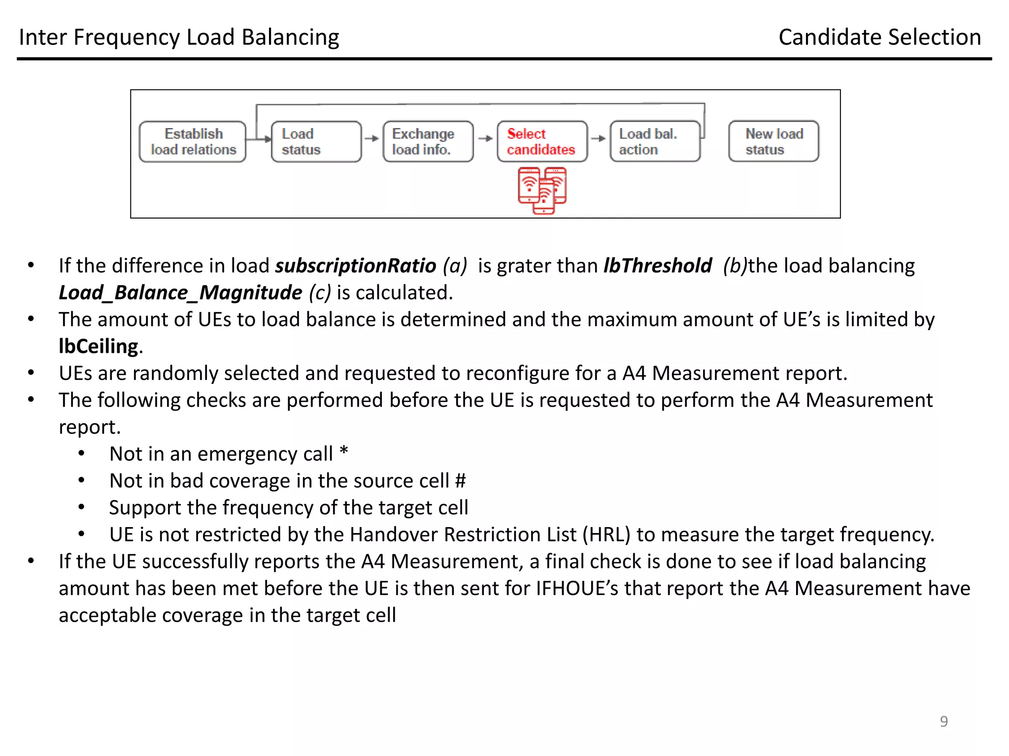
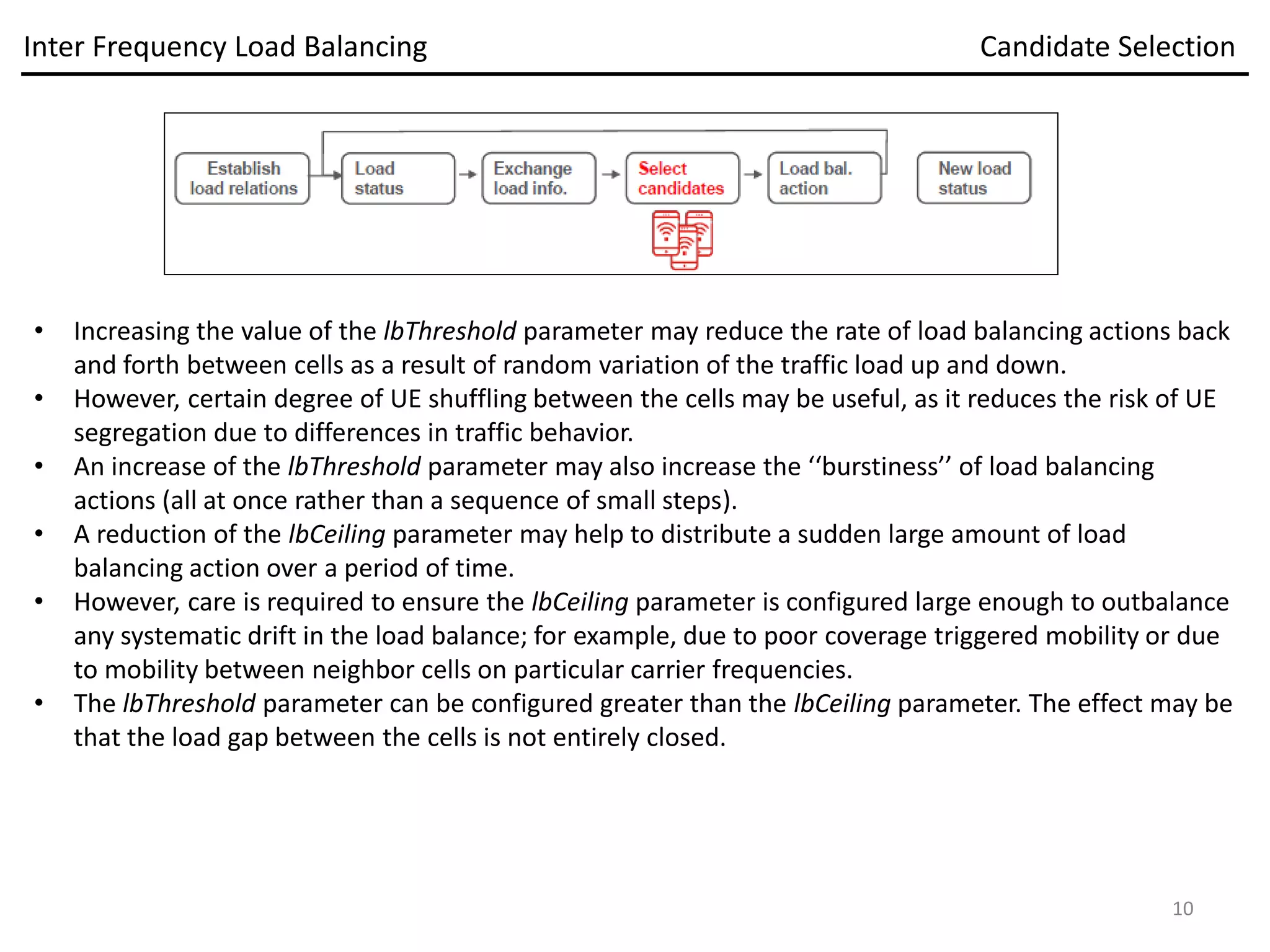
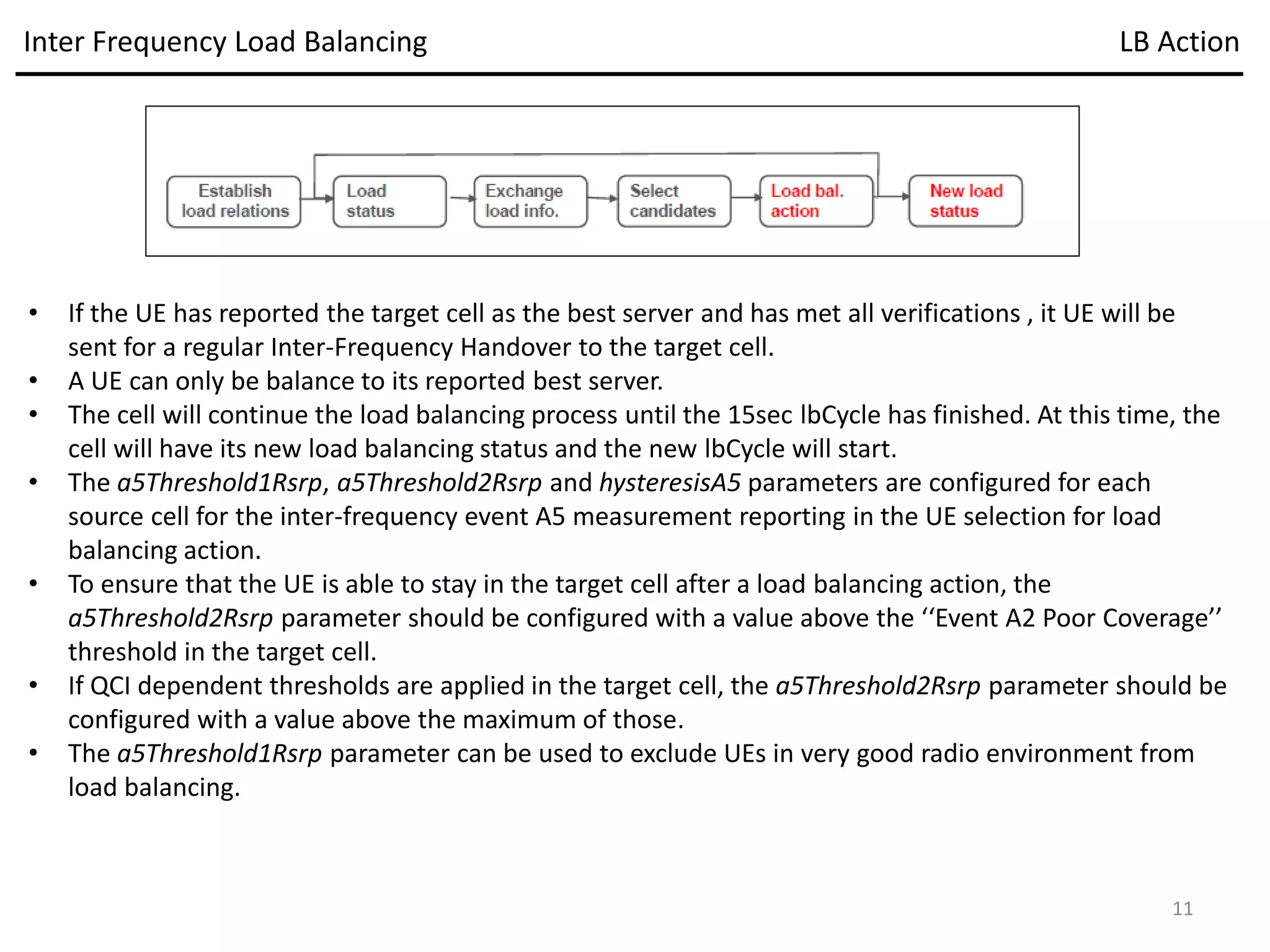
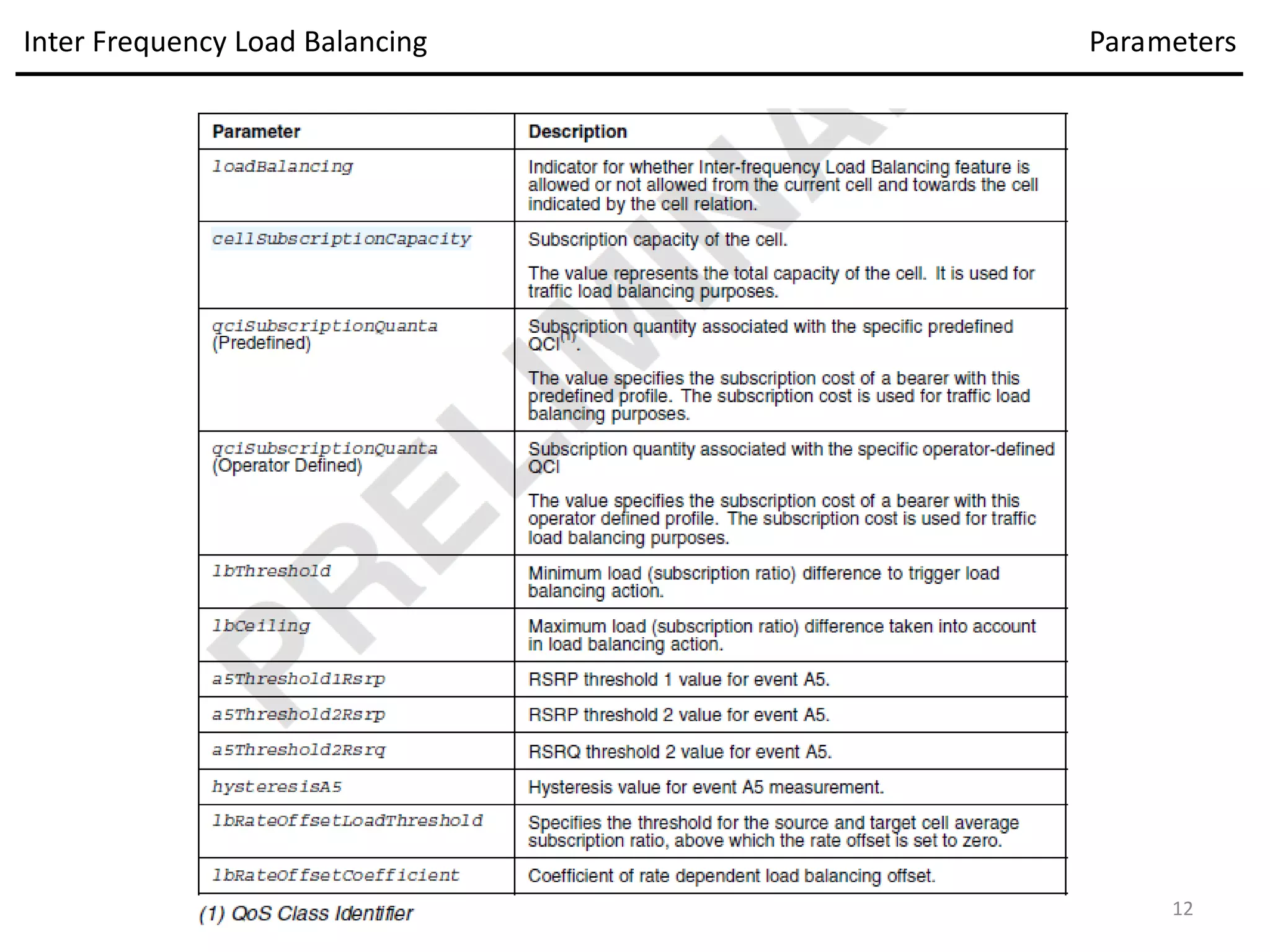
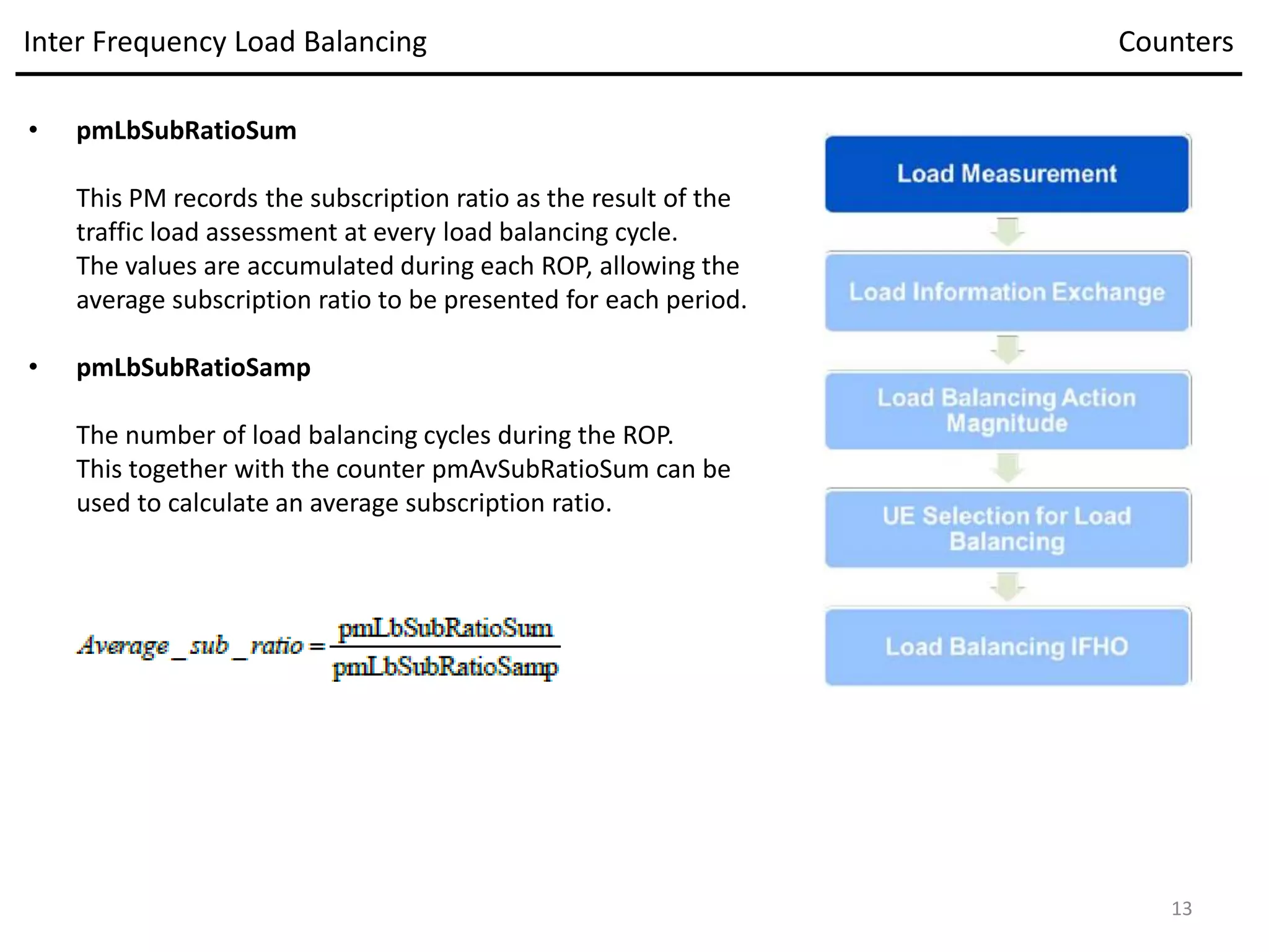
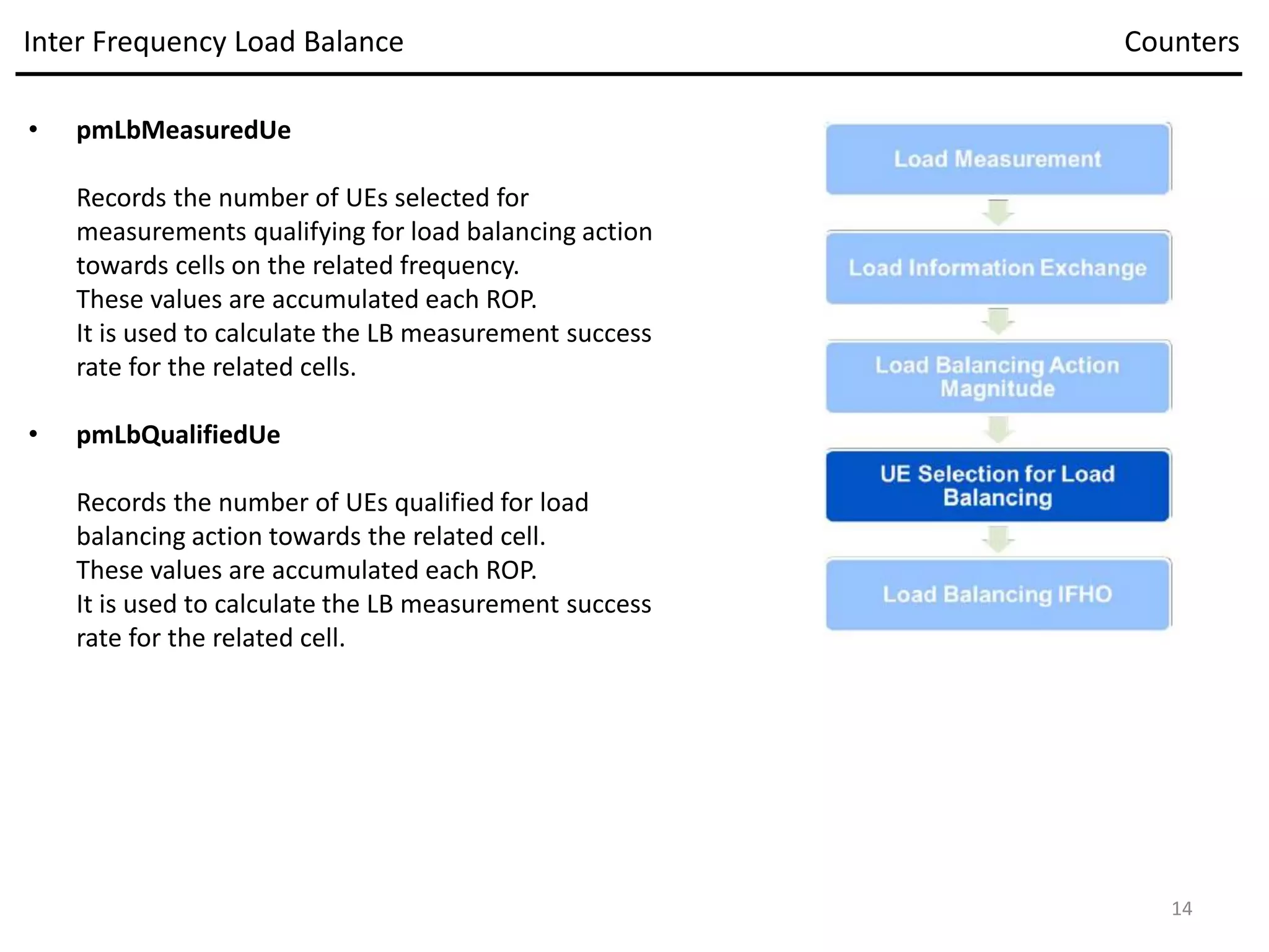
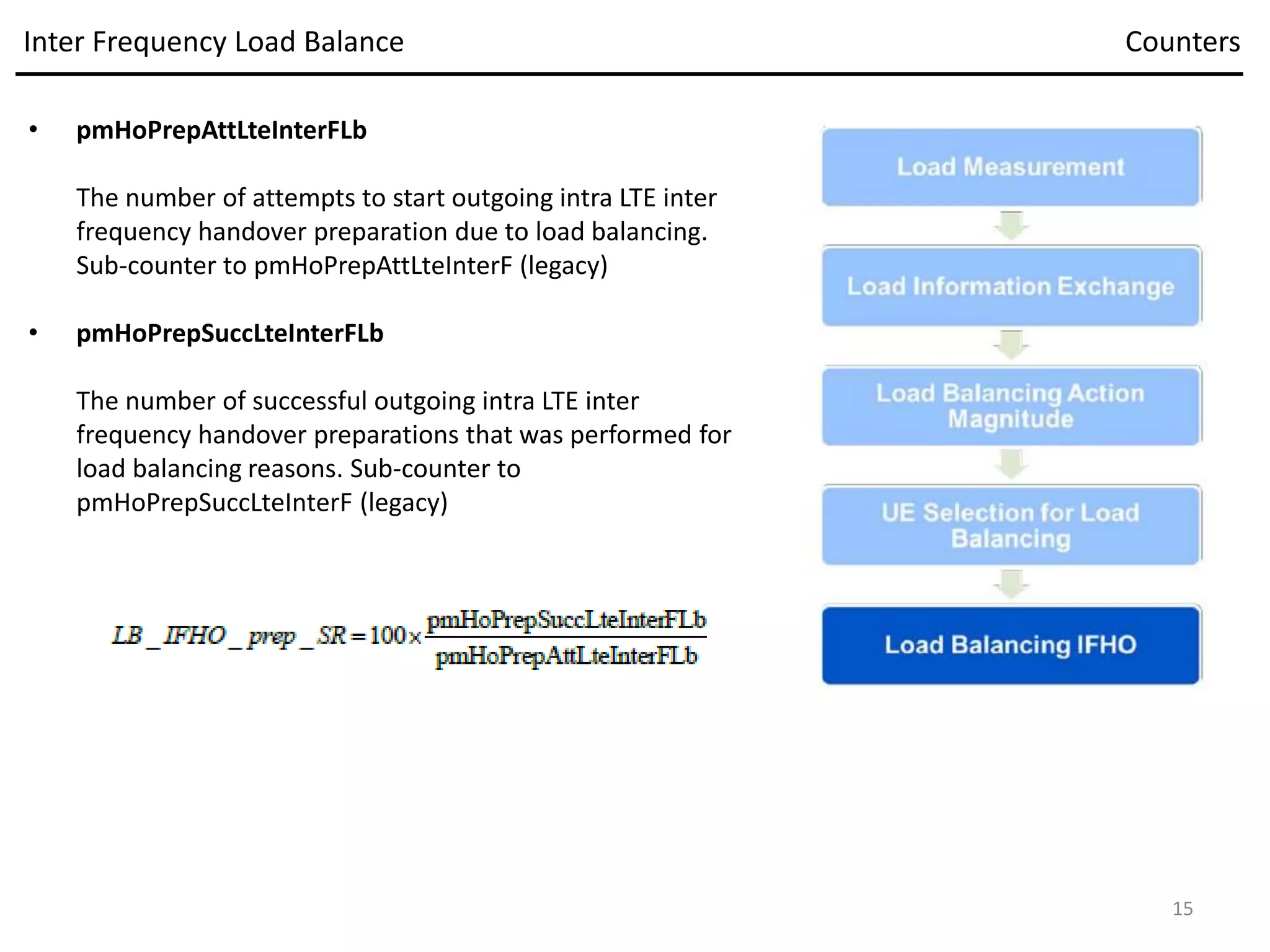
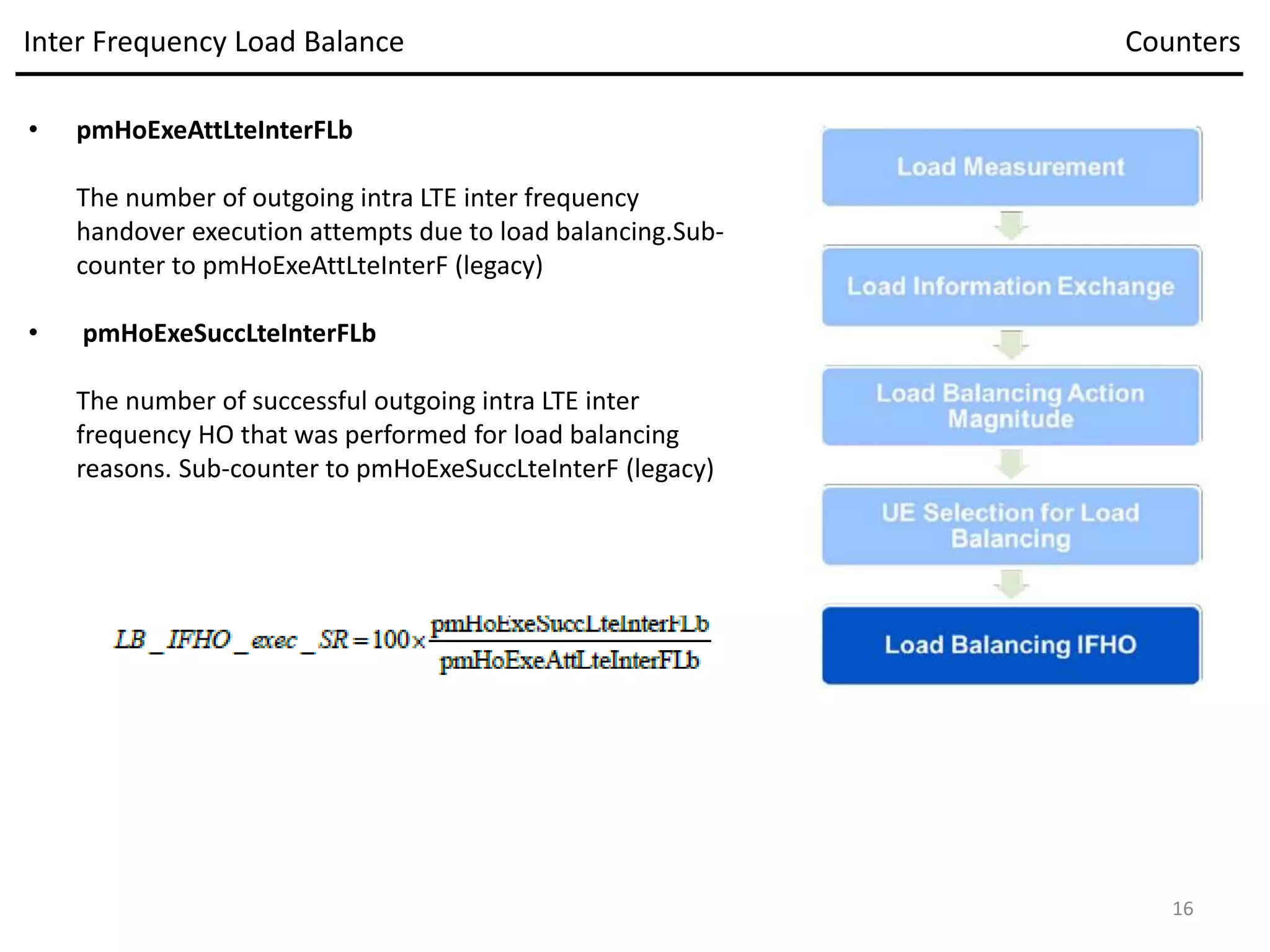
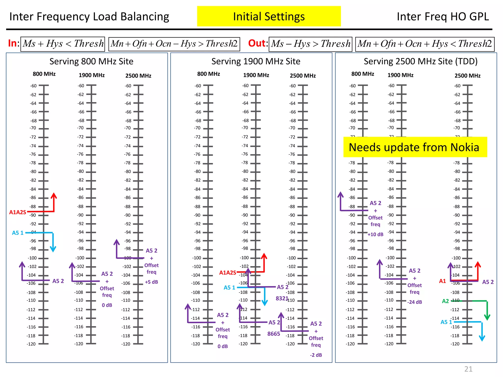
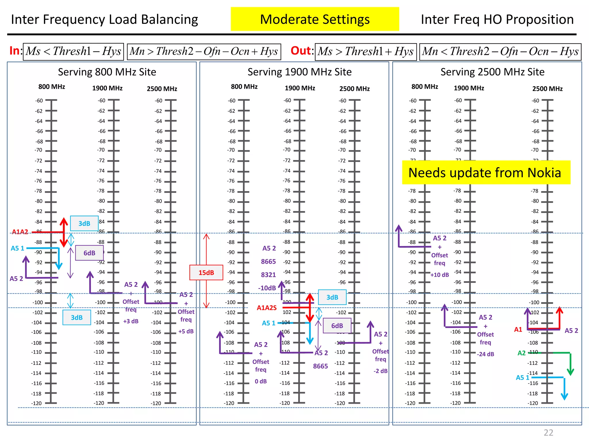
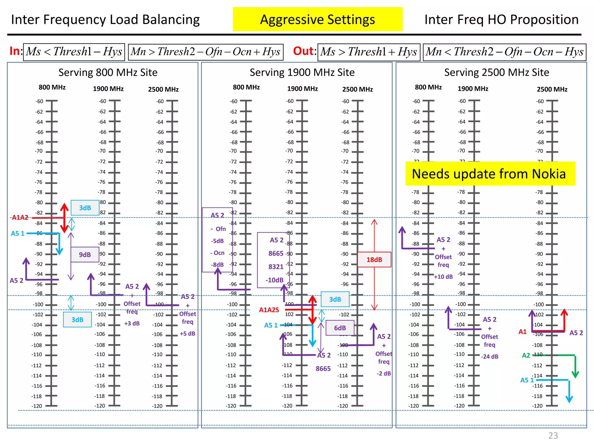
The document discusses the requirements and configuration of Inter Frequency Load Balancing (IFLB) in LTE networks. IFLB aims to balance traffic load across cells on different frequencies by offloading user equipment between those cells. Key steps in IFLB include determining cell load, exchanging load information, selecting offload candidates, and handing users over to target cells if their signal quality is sufficient. The document provides guidance on setting parameters that control IFLB behavior and thresholds.
Hello my friends
Unfortunately, if you want any of these files, please contact me by email and mention any reference you find, to give it to you.
My email: molham.shoriss@outlook.com
LTE
LTE Introduction
LTE Fundamental
LTE RNP Introduction
LTE Principles (Huawei eRAN 3.0)
LTE Access Fault Diagnosis
LTE Access Transport Network Dimensioning
LTE Air Interface ISSUE 1.05
LTE Cell Planning ISSUE1.10
LTE eRAN 3.0 Scheduling - Feature Parameter Description
LTE eRAN3.0 Idle Mode Behavior
LTE eRAN3.0 KPI Introduction
LTE eRAN3.0 - Mobility Management in Connected Mode - Feature Parameters Description
LTE Handover Fault Diagnosis
LTE Network Tuning ISSUE 1.00
LTE Protocols and Procedure
LTE Radio Network Capacity Dimensioning
LTE Radio Network Coverage Dimensioning
LTE Radio Resource Management Overview
LTE Scheduling
LTE (Eicsson)
01.LTE SAE System Overview
LTE 10A Air Interface
LTE L10A Access Transport Network
LTE L10A Radio Network Design
LTE L12 Initial Tuning
LTE L14 Radio Network Functionality LTE
LTE Protocols and Procedures
LTE System Techniques
LTE Throughput Troubleshooting Techniques
LTE Radio Access Radio Interface Dimensioning and Planning
MIMO in WCDMA and LTE
LTE L14 Radio Network Functionality LTE
LTE Huawei
LTE System Overview
LTE Air Interface
LTE Protocols and Signaling Procedures
LTE Network Performance Management (KPIs)
LTE Radio Network Coverage Dimensioning
LTE Cell Planning
LTE Access Fault Diagnosis
LTE Handover Fault Diagnosis
LTE Call Drop Diagnosis
LTE Traffic Fault Diagnosis
LTE Interference Troubleshooting Guide
LTE Optimization
LTE Troubleshooting Access Failures
Features 1. Idle Mode
Features 2. Intra Rat Handover
Features 3. Power Control
Features 4. Scheduling
Features 5. CS Fallback
Features 6. Physical Channel Resource Management
HedEx for LTE
eRAN_eRAN13.0_02_en_GEG09124
5G
5G System Design (Wiley)
HedEx for 5G
(For Engineer) 5G RAN2.0 Solution Technical Guideline
Hello my friends
Unfortunately, if you want any of these files, please contact me by email and mention any reference you find, to give it to you.
My email: molham.shoriss@outlook.com
Hello my friends
Unfortunately, if you want any of these files, please contact me by email and mention any reference you find, to give it to you.
My email: molham.shoriss@outlook.com
LTE
LTE Introduction
LTE Fundamental
LTE RNP Introduction
LTE Principles (Huawei eRAN 3.0)
LTE Access Fault Diagnosis
LTE Access Transport Network Dimensioning
LTE Air Interface ISSUE 1.05
LTE Cell Planning ISSUE1.10
LTE eRAN 3.0 Scheduling - Feature Parameter Description
LTE eRAN3.0 Idle Mode Behavior
LTE eRAN3.0 KPI Introduction
LTE eRAN3.0 - Mobility Management in Connected Mode - Feature Parameters Description
LTE Handover Fault Diagnosis
LTE Network Tuning ISSUE 1.00
LTE Protocols and Procedure
LTE Radio Network Capacity Dimensioning
LTE Radio Network Coverage Dimensioning
LTE Radio Resource Management Overview
LTE Scheduling
LTE (Eicsson)
01.LTE SAE System Overview
LTE 10A Air Interface
LTE L10A Access Transport Network
LTE L10A Radio Network Design
LTE L12 Initial Tuning
LTE L14 Radio Network Functionality LTE
LTE Protocols and Procedures
LTE System Techniques
LTE Throughput Troubleshooting Techniques
LTE Radio Access Radio Interface Dimensioning and Planning
MIMO in WCDMA and LTE
LTE L14 Radio Network Functionality LTE
LTE Huawei
LTE System Overview
LTE Air Interface
LTE Protocols and Signaling Procedures
LTE Network Performance Management (KPIs)
LTE Radio Network Coverage Dimensioning
LTE Cell Planning
LTE Access Fault Diagnosis
LTE Handover Fault Diagnosis
LTE Call Drop Diagnosis
LTE Traffic Fault Diagnosis
LTE Interference Troubleshooting Guide
LTE Optimization
LTE Troubleshooting Access Failures
Features 1. Idle Mode
Features 2. Intra Rat Handover
Features 3. Power Control
Features 4. Scheduling
Features 5. CS Fallback
Features 6. Physical Channel Resource Management
HedEx for LTE
eRAN_eRAN13.0_02_en_GEG09124
5G
5G System Design (Wiley)
HedEx for 5G
(For Engineer) 5G RAN2.0 Solution Technical Guideline
Hello my friends
Unfortunately, if you want any of these files, please contact me by email and mention any reference you find, to give it to you.
My email: molham.shoriss@outlook.com
In this paper, we discussed about LTE system throughput calculation for both TDD and FDD system.
3GPP LTE technology support both TDD and FDD multiplexing. The paper describes all the factors which affect the throughput like Bandwidth, Modulation, UE category and mulplexing. It also describes how we get throughput 300Mbps in DL and 75Mbps in UL and what are assumptions taken to calculate the same.
Paper describes the steps and formulae to calculate the throughput for FDD system for TDD Config 1 and Config 2.
The throughput calculations shown in this paper is theoretical and limited by the assumptions taken to calculate for calculations
Painless XML Authoring?: How DITA Simplifies XMLScott Abel
Presented at DocTrain East 2007 by Bob Doyle, DITA Users -- This introduction to XML Authoring will acquaint you with over fifty tools aimed at structuring content with DITA. They are not just DITA-compliant authoring tools (editors) for writers. They also include content management systems (CMS), translation management systems (TMS), and dynamic publishing engines that fully support DITA. You will also need to know about tools that convert legacy documents to DITA and help to design stylesheets for DITA deliverables. The best DITA tools for technical communicators implement the DITA standard while hiding all the complexity of the underlying XML (eXtensible Markup Language).
As a tech writer and not a tech, you should be able to forget about XML - except to know that you are using it (DITA is XML) and that it consists of named content elements (or components) with attributes. You need to know enough about the content elements so you can reference (conref) them for reuse. You need to know about their attributes so you can filter on them for conditional processing. And you should appreciate that because components are uniquely identifiable they lend themselves perfectly to automated dynamic assembly using a publishing engine.
We will describe how you can get started with structured writing without knowing XML or installing anything.
The promise of topic-based structured authoring is not simply better documentation. It is the creation of mission-critical information for your organization, written with a deep understanding of your most important audiences, that can be repurposed to multiple delivery channels and localized for multilingual global markets. You are not just writing content, you are preparing the information deliverables that enhance the value of your organization in all its markets.
To do that well, you must understand the latest tools in structured writing that are revolutionizing corporate information systems - today in documentation but tomorrow throughout the enterprise, from external marketing to internal human resources. Whether you are trying to push a new product into a new market or are “onboarding” a new employee, the need for high quality information to educate the customer or train the new salesperson is a challenge for technical communicators. You need to think outside the docs!
The key idea behind Darwin Information Typing Architecture is to create content in small chunks or modules called topics. A topic is the right size when it can stand alone as meaningful information. Topics are then assembled into documents using DITA maps, which are hierarchical lists of pointers or links to topics. The pointers are called “topicrefs” (for topic references).
Think of documents as assembled from single-source component parts. Assembly can be conditional, dependent on properties or metadata “tags” you attach to a topic. For example, the “audience” property might be “beginner” or “advanced.”
At a still finer level of granularity, individual elements of a topic can also be assigned property tags for conditional assembly. More importantly, a topic element can be assigned a unique ID that makes it a content component reusable in other topics.
As you will learn, DITA is a leading technology for “component content management,” which multiplies the value of your work. You need to leverage DITA and structured content to multiply your income.
Strategies for enhancing utilization levels in under utilized cells through targeted advertising using means such as SMS/ cell broadcast (SABP) require estimating the load and usage levels in those UMTS cells. This note lists the considerations involved in making this estimate and briefly describes the kinds of algorithms employed to maximize utilization levels by maximizing the efficient use of radio and network resources.
The amount of electric power that can be moved or transferred reliably from one area to another area of the interconnected transmission systems by way of all transmission lines (or paths) between those areas under specified system conditions……….16-Mar-2007(FERC)
As per 1995 document of NERC, following conditions need to be satisfied:
all facility loadings in pre-contingency are within normal ratings and all voltages are within normal limits
systems stable and capable of absorbing the dynamic power swings
before any post-contingency operator-initiated system adjustments are implemented, all transmission facility loadings are within emergency ratings and all voltages are within emergency limits”
Cell load KPIs in support of event triggered Cellular Yield MaximizationAsoka Korale
A scheme for enhancing cellular yield in 3G systems. Cell utilization can be enhanced by observing cell load on a near real time basis and making offers to those subscribers in under utilized cells at those times when the cell can accommodate a higher level of traffic.
Tungsten Connector / Proxy is truly the secret sauce for the Tungsten Clustering solution. Watch this webinar to learn how the Tungsten Connector enables zero-downtime MySQL maintenance via the manual switch operation, and gain an understanding of the various configuration options for doing local reads in remote composite clusters.
AGENDA
- Review the cluster architecture
- Understand the role of the Connector
- Describe Connector deployment best practices (app, dedicated with lb, db with lb)
- Explore zero-downtime MySQL maintenance using the manual role switch procedure
- Learn about Connector routing patterns inside a composite cluster
- Illustrate a manual site switch
- Explain read affinity and the vast performance improvement of local reads
- Examine Connector multi-cluster support
Load Balancing In Distributed ComputingRicha Singh
Load Balancing In Distributed Computing
The goal of the load balancing algorithms is to maintain the load to each processing element such that all the processing elements become neither overloaded nor idle that means each processing element ideally has equal load at any moment of time during execution to obtain the maximum performance (minimum execution time) of the system
Energy Efficient LEACH protocol for Wireless Sensor Network (I-LEACH)ijsrd.com
in the wireless sensor networks (WSNs), the sensor nodes (called motes) are usually scattered in a sensor field an area in which the sensor nodes are deployed. These motes are small in size and have limited processing power, memory and battery life. In WSNs, conservation of energy, which is directly related to network life time, is considered relatively more important souse of energy efficient routing algorithms is one of the ways to reduce the energy conservation. In general, routing algorithms in WSNs can be divided into flat, hierarchical and location based routing. There are two reasons behind the hierarchical routing Low Energy Adaptive Clustering Hierarchy (LEACH) protocol be in explored. One, the sensor networks are dense and a lot of redundancy is involved in communication. Second, in order to increase the scalability of the sensor network keeping in mind the security aspects of communication. Cluster based routing holds great promise for many to one and one to many communication paradigms that are pre valentines or networks.
THRESHOLD SENSITIVE HETEROGENOUS ROUTING PROTOCOL FOR BETTER ENERGY UTILIZATI...ijassn
Advancements in WSN have led to the wide applicability of sensor network in various fields. WSNs basic classification is Reactive and Proactive network. Reactive networks responds to the very immediate changes in its environment in required parameters of interest, as opposed to the Proactive network, due to continuous sensing nature of WSN. To make it more efficient and improved in terms of Energy in network’s
lifetime, we need to reduce the energy expense in the network model, which is one of the most significant issues in wireless sensor networks (WSNs) [1, 2]. In this paper, we proposed an efficient version of TSEP Protocol, which prolongs the networks lifetime by efficient utilization of sensor energy, as we have simulated. We evaluated the performance of our protocol and compared the results with the TSEP. And from the results of simulation, it can be concluded easily that our proposed efficient routing protocol performs better in terms of network lifetime and stability period
THRESHOLD SENSITIVE HETEROGENOUS ROUTING PROTOCOL FOR BETTER ENERGY UTILIZATI...ijassn
Advancements in WSN have led to the wide applicability of sensor network in various fields. WSNs basic classification is Reactive and Proactive network. Reactive networks responds to the very immediate changes in its environment in required parameters of interest, as opposed to the Proactive network, due to continuous sensing nature of WSN. To make it more efficient and improved in terms of Energy in network’s lifetime, we need to reduce the energy expense in the network model, which is one of the most significant issues in wireless sensor networks (WSNs) [1, 2]. In this paper, we proposed an efficient version of TSEP Protocol, which prolongs the networks lifetime by efficient utilization of sensor energy, as we have simulated. We evaluated the performance of our protocol and compared the results with the TSEP. And
from the results of simulation, it can be concluded easily that our proposed efficient routing protocol performs better in terms of network lifetime and stability period.
2. • Introduction
The description given on the next pages can be applied to Ericsson, Nokia or other vendor. It is always
needed to verify the associated features per Vendor and the associated “Golden Parameters List” and
strategy per operators.
• Requirements
For E/// LTE network, the following must be fulfilled at feature activation:
• A license key must be activated to operate these features:
• Coverage-Triggered Inter-Frequency Handover feature
• Inter-frequency Load Balancing feature
• The cell relations where load balancing is desired must be configured to allow load balancing actions
and reporting. The loadBalancing parameter is set to ALLOWED in the desired EUtranCellRelation MO.
• Load balancing between cells in different RBS nodes requires an X2 connection between the RBS
nodes.
More information about this feature and related topics can be found in the following documentation:
• 3GPP TS 36.300, Overall description; Stage 2
• 3GPP TS 36.331, Radio Resource Control (RRC); Protocol Specification
• 3GPP TS 36.423, X2 Application Protocol (X2AP)
Inter Frequency Load Balancing (IFLB) Network Requirements
2
3. • Subscription Ratio Definition
The IFLB feature uses a model for the assessment of traffic load in a cell, wherein the expected load of
each E-RAB is quantified based on the QoS class to which it belongs as follows:
• A qciSubscriptionQuanta value is associated with each E-RAB, and it is an estimate of the
expected traffic activity for an E-RAB of the particular QoS class.
• The assessment of traffic load in a cell is made in terms of a ‘‘subscription ratio’’ value;
• The cellSubscriptionCapacity value is an estimate of the total amount of qciSubscriptionQuanta
values the cell is expected to accommodate at full system load.
• A configuration of the qciSubscriptionQuanta and the cellSubscriptionCapacity values is
required to obtain the desired load balancing behavior.
• It enables the Inter-frequency Load Balancing feature to perform load balancing between cells
with different mix of UE population and between cells with different traffic capacity.
• The exchange of cell load information is performed over X2 private messages.
• Each cell may receive load reports from one or more other cells in the same RBS or in the
remote RBS.
• The selection of target cells is controlled with the loadBalancing parameter.
Inter Frequency Load Balancing Definitions
3
4. In practice, the following recommendations are made:
• The qciSubscriptionQuanta parameter for a GBR type of E-RAB is chosen in proportion to the typical
‘‘guaranteed downlink bit rate’’ (in kbps) for the particular QCI:
• QCI=1 (conversational voice) the value depends on the typical voice codec in use.
• Other GBR types of E-RAB (QCI=2..4, …) the value depends on the type of streaming media. The
qciSubscriptionQuanta parameter for a non-GBR type of E-RAB is chosen in proportion to what
is considered an acceptable downlink bit rate (in kbps) for UE in connected mode in LTE RAN at
high load: The ‘‘default’’ non-GBR types of E-RAB are activated whenever the UE enters
connected mode, irrespective if they are going to be used; conservative values should be
chosen, reflecting an expected low or moderate duty rate on these E-RABs.
• QCI=5 (default for IMS signaling), the expected bit rate is typically very low (not exceeding 3
kbps).
• for a default Internet Service Provision (ISP) E-RAB, a suitable value can be based on the typical
UE data consumption over a longer time period in relation to the time spent in connected
mode over the same time period; the value should focus on the conditions in LTE RAN at high
load.
• For on-demand non-GBR types of E-RAB, values should be chosen based on the typical
minimum QoS requirements of the intended applications.
Inter Frequency Load Balancing Definitions
4
5. (every 15 seconds)
1. Determine cell load status
2. Exchange and compare load status with
target relations
3. If own cell has higher load than target,
select offload candidate UEs
4. If target has good RSRP, then send UEs to
target to balance load
5. New own cell load status
Inter Frequency Load Balancing Flow Overview
Inter-Frequency Load Balancing feature handles uneven distribution of traffic in the Shared RAN
network. For cells that have load relations established, the high-level behavior is:
5
7. Every load balancing cycle, each cell determines its
load status.
The ratio load based is based on total sum of
qciSubscriptionQuanta over cellSubscriptionCapacity
– Subscription quanta is weighted based on QCI and
represents a generic cost of each
bearer.
› The value for each QCI is configured with the
parameter qciSubscriptionQuanta
(QciProfilePredefined / QciProfileOperatorDefined).
Cell subscription capacity represents an estimate of the total cell capacity.
The value for each cell is configured with the parameter cellSubscriptionCapacity (EUtranCellFDD /
EUtranCellTDD).
› Average subscription ratio is observed with the counters pmLbSubRatioSum and pmLbSubRatioSamp
(EUtranCellFDD / EUtranCellTDD)
Inter Frequency Load Balancing Load Status
7
8. This is done based on the following:
(a) Load difference to each target cell. Source and target cells exchange load info and the difference in
load are checked against minimum and maximum offload thresholds.
(b) Minimum load difference, lbThreshold, to trigger load balancing action.
Total off-loading from the source cell. If multiple target cells exist, the total off-loading is split
between those.
(c) Maximum load difference, lbCeiling, taken into account in one round of load balancing action.
Inter Frequency Load Balancing Info Exchange
(a)
(b)
(c)
8
9. • If the difference in load subscriptionRatio (a) is grater than lbThreshold (b)the load balancing
Load_Balance_Magnitude (c) is calculated.
• The amount of UEs to load balance is determined and the maximum amount of UE’s is limited by
lbCeiling.
• UEs are randomly selected and requested to reconfigure for a A4 Measurement report.
• The following checks are performed before the UE is requested to perform the A4 Measurement
report.
• Not in an emergency call *
• Not in bad coverage in the source cell #
• Support the frequency of the target cell
• UE is not restricted by the Handover Restriction List (HRL) to measure the target frequency.
• If the UE successfully reports the A4 Measurement, a final check is done to see if load balancing
amount has been met before the UE is then sent for IFHOUE’s that report the A4 Measurement have
acceptable coverage in the target cell
Inter Frequency Load Balancing Candidate Selection
9
10. • Increasing the value of the lbThreshold parameter may reduce the rate of load balancing actions back
and forth between cells as a result of random variation of the traffic load up and down.
• However, certain degree of UE shuffling between the cells may be useful, as it reduces the risk of UE
segregation due to differences in traffic behavior.
• An increase of the lbThreshold parameter may also increase the ‘‘burstiness’’ of load balancing
actions (all at once rather than a sequence of small steps).
• A reduction of the lbCeiling parameter may help to distribute a sudden large amount of load
balancing action over a period of time.
• However, care is required to ensure the lbCeiling parameter is configured large enough to outbalance
any systematic drift in the load balance; for example, due to poor coverage triggered mobility or due
to mobility between neighbor cells on particular carrier frequencies.
• The lbThreshold parameter can be configured greater than the lbCeiling parameter. The effect may be
that the load gap between the cells is not entirely closed.
Inter Frequency Load Balancing Candidate Selection
10
11. • If the UE has reported the target cell as the best server and has met all verifications , it UE will be
sent for a regular Inter-Frequency Handover to the target cell.
• A UE can only be balance to its reported best server.
• The cell will continue the load balancing process until the 15sec lbCycle has finished. At this time, the
cell will have its new load balancing status and the new lbCycle will start.
• The a5Threshold1Rsrp, a5Threshold2Rsrp and hysteresisA5 parameters are configured for each
source cell for the inter-frequency event A5 measurement reporting in the UE selection for load
balancing action.
• To ensure that the UE is able to stay in the target cell after a load balancing action, the
a5Threshold2Rsrp parameter should be configured with a value above the ‘‘Event A2 Poor Coverage’’
threshold in the target cell.
• If QCI dependent thresholds are applied in the target cell, the a5Threshold2Rsrp parameter should be
configured with a value above the maximum of those.
• The a5Threshold1Rsrp parameter can be used to exclude UEs in very good radio environment from
load balancing.
Inter Frequency Load Balancing LB Action
11
13. • pmLbSubRatioSum
This PM records the subscription ratio as the result of the
traffic load assessment at every load balancing cycle.
The values are accumulated during each ROP, allowing the
average subscription ratio to be presented for each period.
• pmLbSubRatioSamp
The number of load balancing cycles during the ROP.
This together with the counter pmAvSubRatioSum can be
used to calculate an average subscription ratio.
Inter Frequency Load Balancing Counters
13
14. • pmLbMeasuredUe
Records the number of UEs selected for
measurements qualifying for load balancing action
towards cells on the related frequency.
These values are accumulated each ROP.
It is used to calculate the LB measurement success
rate for the related cells.
• pmLbQualifiedUe
Records the number of UEs qualified for load
balancing action towards the related cell.
These values are accumulated each ROP.
It is used to calculate the LB measurement success
rate for the related cell.
Inter Frequency Load Balance Counters
14
15. • pmHoPrepAttLteInterFLb
The number of attempts to start outgoing intra LTE inter
frequency handover preparation due to load balancing.
Sub-counter to pmHoPrepAttLteInterF (legacy)
• pmHoPrepSuccLteInterFLb
The number of successful outgoing intra LTE inter
frequency handover preparations that was performed for
load balancing reasons. Sub-counter to
pmHoPrepSuccLteInterF (legacy)
Inter Frequency Load Balance Counters
15
16. • pmHoExeAttLteInterFLb
The number of outgoing intra LTE inter frequency
handover execution attempts due to load balancing.Sub-
counter to pmHoExeAttLteInterF (legacy)
• pmHoExeSuccLteInterFLb
The number of successful outgoing intra LTE inter
frequency HO that was performed for load balancing
reasons. Sub-counter to pmHoExeSuccLteInterF (legacy)
Inter Frequency Load Balance Counters
16
17. According to 3GPP **, the UE shall:
1) consider the entering condition for this event to be satisfied when
2) consider the leaving condition for this event to be satisfied when
where:
• Ms is the measurement of the serving cell, not taking into account any offsets.
• Mn is the measurement of the neighboring cell, not taking into account any offsets.
• Ofn is the frequency offset corresponding to the frequency of the neighbor cell.
• Ocn is the cell specific offset of the neighbor cell.
• Hys is the hysteresis parameter for this event .
• Thresh1 is the threshold parameter for this event (i.e. a5-Threshold1).
• Thresh2 is the threshold parameter for this event (i.e. a5-Threshold2).
• Mn, Ms are expressed in dBm in case of RSRP, or in dB in case of RSRQ.
• Ofn, Ocn, Hys are expressed in dB.
• Thresh1 is expressed in the same unit as Ms.
• Thresh2 is expressed in the same unit as Mn.
** 3GPP 36331 – RRC Protocol Specification, Measurement Report Triggering, Event A5 (Serving becomes worse than threshold1 and neighbour becomes
better than threshold2)
Inter Frequency Load Balance Event A5 Description
2ThreshHysOcnOfnMn ThreshHysMs
ThreshHysMs 2ThreshHysOcnOfnMn **
*
17
19. Inter Frequency Load Balancing Settings Plan
The Inter Frequency LB will be applied and it’s parameters will be updated according to:
• The feature should be applied per cell in a vertical relation (i.e. alpha 800 <-> alpha 1900 (1)&(2))
• IFLB parameters will follow the GPL setting
• A5 event thresholds will be the same for IFLB and for coverage trigger
• The feature will be applied as need according to CFR caused by load
• Test Site: zzz
• According to GPL, the following parameters must be updated:
• lbActivationThreshold: Not active from 8321 to 8665
• loadBalancing between same sector and different bands should be set to 1 (Allowed)
19
20. Inter Frequency Load Balancing Settings Plan
The Inter Frequency LB will be applied and it’s parameters will be updated according to:
20