Downloaded 267 times
![1—LTE
Channel Mapping
• Mapping of EPS/radio bearers into logical channels is performed
• Mapping of logical channels into transport channels is performed
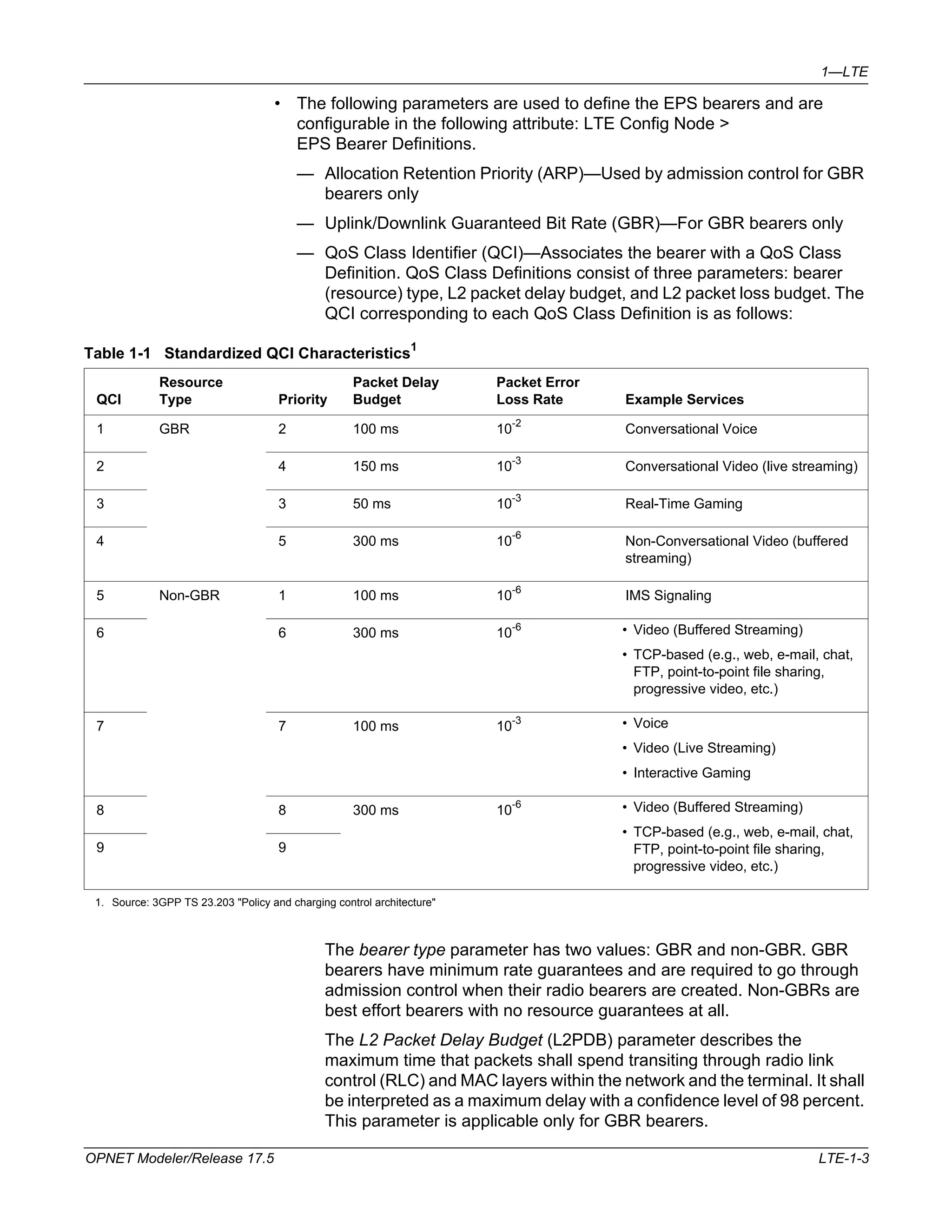
The following table shows the logical channels that are modeled together with
their transport channels and usage:
Table 1-2 Mapping of Logical Channels to Transport Channels
Direction Logical Channel Transport Channel Usage
Downlink Common Control Channel
Downlink Shared Channel (DL-SCH) Control messages sent before
UE's RRC connection
Dedicated Traffic Channel
(DTCH)
Downlink user data
Dedicated Control Channel
(DCCH)
Downlink control information
Uplink Common Control Channel
Uplink Shared Channel (UL-SCH) Control message sent before
RRC connection
Dedicated Traffic Channel
(DTCH)
Uplink user data
Dedicated Control Channel
(DCCH)
Uplink control information
The “starting” modulation and coding rate of the UE for both DL-SCH and
UL-SCH is determined by the “Modulation and Coding Rate” attribute
configured on the UE. If the simulation is run in the efficiency mode “PHY
Disabled”, this MCS index does not change during the simulation duration.
Otherwise, the MCS index for each UL-SCH and DL-SCH adapts itself
depending upon the channel conditions.
• MCS index values and their mapping to TBS indices are based on table
7.1.7.1-1 for PDSCH and table 8.6.1-1 for PUSCH in [36.213]
• The transport block size, in bits, is determined by applying the TBS index
(ITBS) and the number of transport blocks (NPRB) in table 7.1.7.2.1-1 of
[36.213]
Between each UE and its eNodeB, SRB0 and SRB1 are the radio bearers of
CCCH and DCCH, respectively. There is a separate radio bearer for the Default
bearer and each active EPS bearer.
(CCCH)
(CCCH)
LTE-1-12 OPNET Modeler/Release 17.5](https://image.slidesharecdn.com/ltemodeldrx-140912123921-phpapp02/75/Lte-model-drx-12-2048.jpg)
![1—LTE
Frame Generation and Scheduler
A common scheduler is used for the following tasks:
• At eNodeBs, while generating the MPDUs of a downlink subframe
• At eNodeBs, while creating the uplink grants for an uplink subframe
• At UEs, while filling an uplink grant with the data of active bearers
The scheduler operates based on the following main rules:
• Signaling bearers (that is, bearers carrying protocol packets) have higher
priority over data bearers
• GBR bearers have priority over non-GBR bearers. One exception is that
non-GBR bearers with a QCI of “5” have higher priority over GBR bearers.
• Frame capacity is expected to be sufficient to handle all the GBR bearer
traffic, since their radio bearers are accepted only through admission control.
The scheduling algorithm used for servicing the GBR bearers is proportional
fair scheduling, which guarantees a minimum transport of the bit rate
specified in the EPS bearer contract with delays below the values that are
specified in Table 1-1 on page LTE-1-3. Traffic contract for an uplink logical
channel group is the combination of the individual traffic contracts of its GBR
bearer members. The combined bit rate is the sum of the individual bearers'
bit rates. The combined delay is the minimum of the individual bearers'
delays.
— The remaining frame capacity is given to non-GBR bearers. The
non-GBR bearers are serviced using a fairness scheduling scheme, in
which available resources are shared equally among bearers with data
when they have the same QCI.
• In some cases, GBR bearers have traffic that exceeds their contract due to
underestimation of RLC and MAC layer overheads or due to a higher than
expected load from higher layers. In such cases, the excess traffic of GBR
bearers are served by the scheduler the same way the traffic of non-GBR
bearers is served but only after all the traffic of regular non-GBR bearers is
handled.
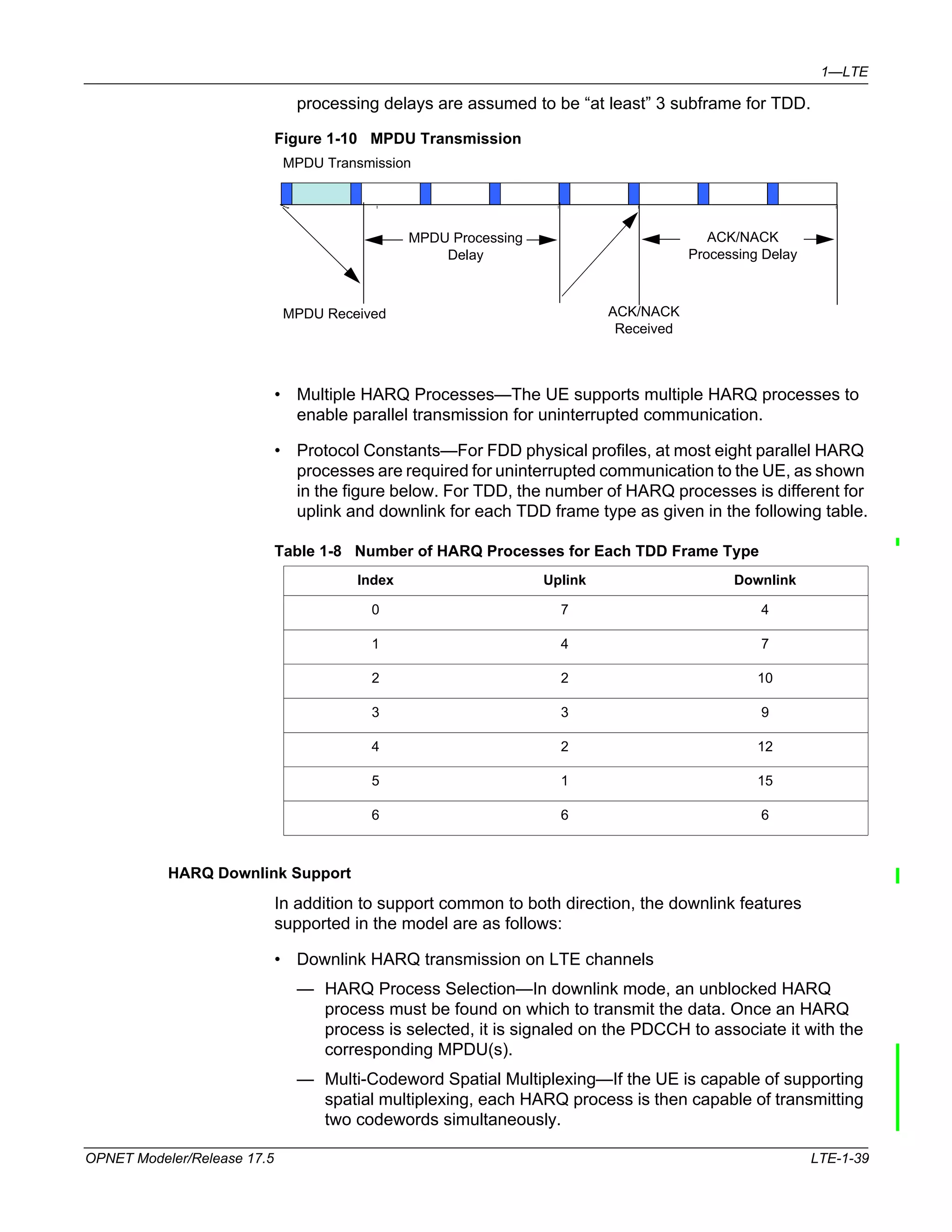
— The frame generator is run in every subframe for the FDD mode. For the
TDD mode, the frame generator is run only when the present subframe
is downlink. Grants for future uplink subframes are signaled in the
present downlink subframe. For the FDD, grants are signaled for an
uplink four subframes from now. For the TDD, this is determined by Table
10.1-1 in standard [36.213].
LTE-1-14 OPNET Modeler/Release 17.5](https://image.slidesharecdn.com/ltemodeldrx-140912123921-phpapp02/75/Lte-model-drx-14-2048.jpg)
![1—LTE
Fixed Parameters
• Frame Structure Type: Type 1
— Frame Length: 10 ms
— Subframe length:1 ms
— Slot length: 0.5 ms
• Frequency Domain
— A resource block consists of 12 sub-carriers, each 15 kHz wide. The
length of a resource block is one slot.
— A resource element is a tile that is one symbol wide and one sub-carrier
high. Therefore a resource block has 84 or 72 resource elements
depending on the configured cyclic prefix length.
— A pair of two Resource Blocks (RBs) is the minimum allocation unit used
by the scheduler while determining the allocations on a frame. The
pairing is in time domain, making the allocation unit one subframe (1 ms)
in length.
— Downlink reference symbols occupy four resource elements in each RB
of the downlink channel. This overhead is accounted for while computing
the frame capacity for the admission control procedure.
— Uplink reference symbols occupy 12 resource elements in each RB of the
uplink channel. This overhead is accounted for while computing the
frame capacity for the admission control procedure.
Configurable Parameters on LTE Config Node
• Duplexing Scheme—Both Frequency Division Duplex (FDD) and Time
Division Duplex (TDD) are modeled. FDD Profiles are configured under
LTE PHY Profiles > FDD Profiles and TDD Profiles are configured under
LTE PHY Profiles > TDD Profiles.
FDD/TDD
Parameters
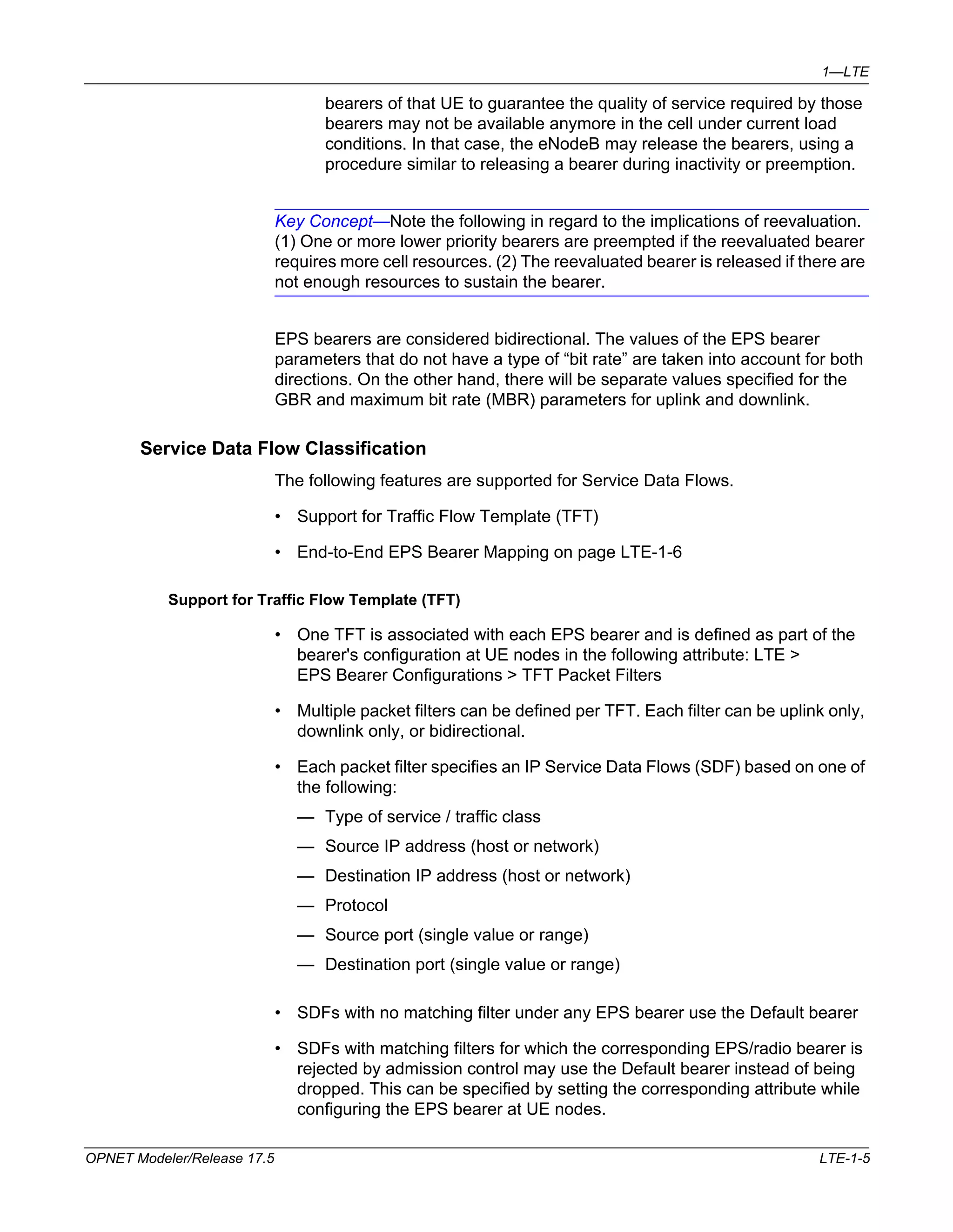
• Bandwidth—Allowed values are 1.4, 3.0, 5.0, 10.0, 15.0, and 20.0 MHz. For
FDD profiles, this is configurable under FDD Profiles >
UL SC-FDMA Channel Configuration > Bandwidth for uplink and
FDD Profiles > DL OFDMA Channel Configuration > Bandwidth for
downlink. For TDD profiles, this is configurable under TDD Profiles >
TDD Channel Configuration > Bandwidth. The respective number of
resource blocks NRB is as follows:
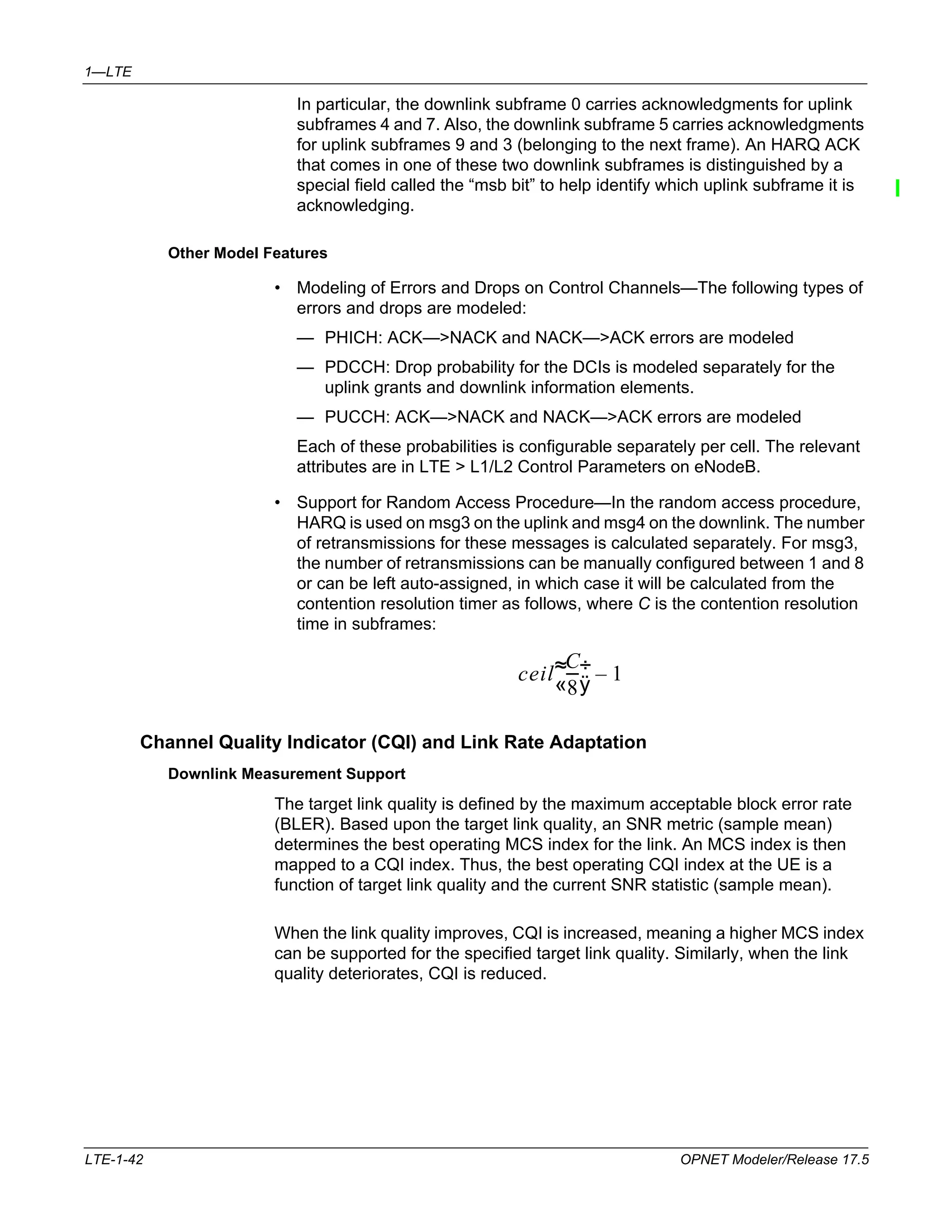
Table 1-4 Channel Bandwidth Parameters1
Channel Bandwidth
BWChannel [MHz] 1.4 3 5 10 15 20
NRB 6 15 25 50 75 100
1. 3GPP TS 36.101 "User Equipment (UE) radio transmission and reception
LTE-1-22 OPNET Modeler/Release 17.5](https://image.slidesharecdn.com/ltemodeldrx-140912123921-phpapp02/75/Lte-model-drx-22-2048.jpg)
![1—LTE
• Base Frequency—Determines the operational frequency of the channel
together with the channel bandwidth. For FDD profiles, this is configurable
under FDD Profiles > UL SC-FDMA Channel Configuration >
Base Frequency for uplink and FDD Profiles >
DL OFDMA Channel Configuration > Base Frequency for downlink. For TDD
profiles, this is configurable under TDD Profiles >
TDD Channel Configuration > Base Frequency.
• Cyclic Prefix Length—Allowed values include normal cyclic prefix and
extended cyclic prefix, which result in seven and six symbols per slot,
respectively. For FDD profiles, this is configurable under FDD Profiles >
UL SC-FDMA Channel Configuration > Cyclic Prefix Length for uplink and
FDD Profiles > DL OFDMA Channel Configuration > Cyclic Prefix Length for
downlink. For TDD profiles, this is configurable under TDD Profiles >
TDD Channel Configuration > Cyclic Prefix Length.
TDD Only
Parameters
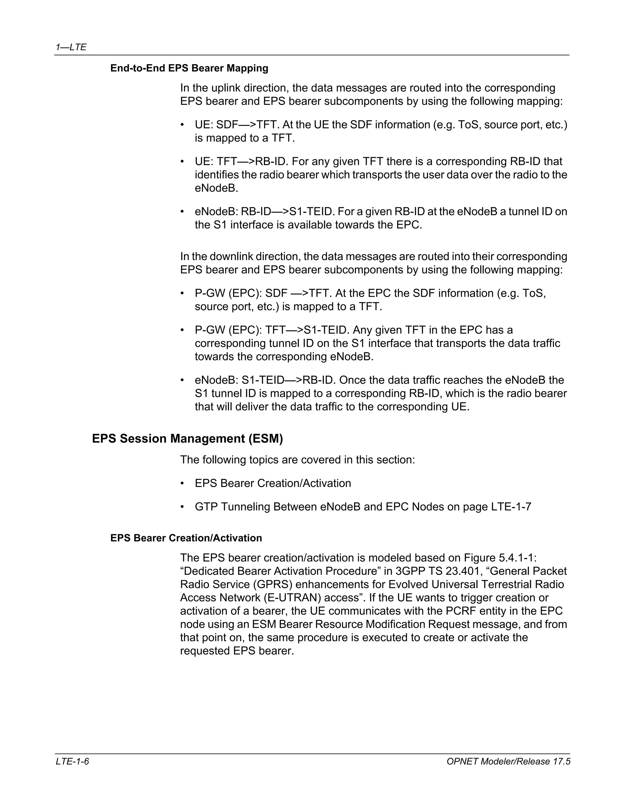
• TDD Channel Index—Determines the "type" of TDD physical profile. Seven
types are defined in standard [36.213]. Each type differentiates itself from the
others in how the Uplink and Downlink subframes repeat within one frame.
This is configurable under TDD Profiles > TDD Channel Configuration >
TDD Channel Index.
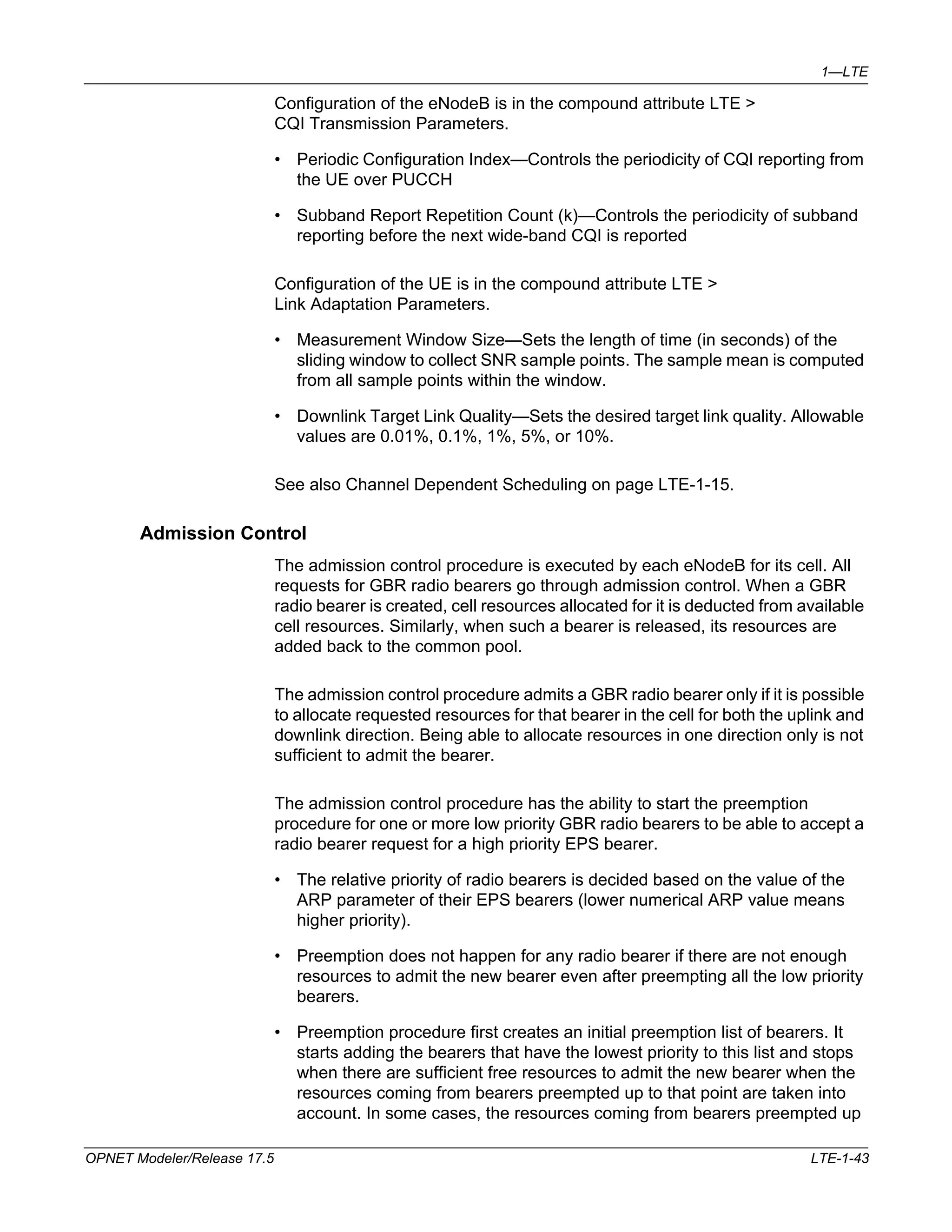
Table 1-5 TDD Configurations
Index
Scheme
(Uplink:Downlink) Downlink %
0 3:2 40
1 2:3 60
2 1:41
3 3:7 70
4 2:8 80
5 1:9 90
6 3:3:2:2 50
1. Default value.
80
OPNET Modeler/Release 17.5 LTE-1-23](https://image.slidesharecdn.com/ltemodeldrx-140912123921-phpapp02/75/Lte-model-drx-23-2048.jpg)
![1—LTE
Multipath Fading
The model supports ITU Multipath Channel models Pedestrian A, Pedestrian B,
Vehicular A, and Vehicular B. You can add more multipath channel models in
the LTE configuration node under the attribute “Multipath Channel Definitions”.
Selecting Multipath Fading Definitions in the UE The Multipath Channel Model
is selectable on each UE in the following attributes:
• LTE > PHY > Multipath Channel Model (Downlink) and
• LTE > PHY > Multipath Channel Model (Uplink)
By default, LTE OFDMA ITU Pedestrian B and
LTE SCFDMA ITU Pedestrian B multipath channel models are configured,
respectively.
Defining the Multipath Channel Models You can define multipath channels in
the LTE configuration utility node that can be selected on each UE node, as
described above. You can either specify the multipath parameters manually or
import the parameters from a file.
Figure 1-8 Setting Multipath Parameters on the LTE Config Node
Key Concept—If you create a directory containing custom files (for example,
custom probability matrixes or Signal-to-Noise [SNR] mapping functions), you
must add this directory to the model directories (mod_dirs) in OPNET Modeler.
Custom probability matrix files and SNR mapping files must be formatted
according to the supported type. For example, “mpath_tpm” (Transition
Probability Matrix) or “mpath_snr” prefixes must be used in the file names,
respectively. These files are text files with the extension gdf, which contain
OPNET Modeler/Release 17.5 LTE-1-33](https://image.slidesharecdn.com/ltemodeldrx-140912123921-phpapp02/75/Lte-model-drx-33-2048.jpg)


![1—LTE
• Downlink HARQ scheduler at the eNodeB
— Downlink Scheduler Sequence—The downlink scheduler adheres to the
following order: a) Random access response messages, b) CCCH
messages, c) All HARQ retransmissions, and d) All new data
transmissions.
— Dynamic Retransmissions—All retransmissions are scheduled
dynamically. A DCI is created on PDCCH to signal the HARQ process ID
for the retransmission element.
Note—Retransmissions are adaptive, and although adaptive modulation and
coding is supported, retransmissions by default use the same MCS index as the
original transmissions.
• HARQ transmission on LTE channels
— MPDU Transmission—HARQ MPDUs are transmitted on PDSCH.
Control information is signaled on PDCCH. The following information is
signaled: HARQ process identifier (three bits), New Data Indicator (one
bit), Redundancy Version (two bits).
If multi-codeword spatial multiplexing is used, then the above information
will be available in PDCCH for each of the two codewords transmitted. If
multi-codeword spatial multiplexing is used, then two ACK/NACK bits,
one per each codeword, will be generated; otherwise only one
ACK/NACK bit will be generated as the response to HARQ
transmissions.
— Acknowledgements—Downlink HARQ ACKs are either sent on PUCCH
or PUSCH. If no PUCCH resource exists for the UE at frame n+k (where
k is 4 for FDD and is given by Table 10.1-1, standard [36.213] for TDD),
eNodeB creates a grant with the minimum block size (one allocation
block). If the grant is successful, the uplink scheduler can reuse this grant
for data transmission. In this case, the HARQ ACK bits will be multiplexed
with uplink data.
For TDD, multiple downlink HARQ processes can be ACKed by a single
ACK bit per codeword on the uplink. This scheme is called ACK bundling.
Table 10.1-1, standard [36.213] details which HARQ transmissions are
ACKed on the current uplink subframe. In the worse case (for TDD index
5), up to nine downlink MPDUs can be acked by a single bit.
— Attributes—Maximum Number of Retransmissions (allowable values:
1-9, default: 3).
LTE-1-40 OPNET Modeler/Release 17.5](https://image.slidesharecdn.com/ltemodeldrx-140912123921-phpapp02/75/Lte-model-drx-40-2048.jpg)
![1—LTE
HARQ Uplink Support
In addition to features common to both directions, the uplink features supported
in the model are as follows:
• Uplink HARQ transmission on LTE channels
— Attributes—Maximum Number of Retransmissions (allowable values:
1-9, default: 3).
— HARQ Process Selection—In uplink, the HARQ process ID is implicit and
is not signaled on PDCCH. The process ID (for FDD) is calculated as
follows:
10*frame_number + subframe_number modulo 8
— For TDD, since the number of HARQ processes is different from 8, the
process ID is not calculated using the formula above. Rather it is
obtained using a static table lookup that is a function of the current
subframe number. For the cases of TDD index 0 or 6, the HARQ process
ID also depends upon the current frame number.
• MPDU Transmission—HARQ MPDU is transmitted on PUSCH. If control
information needs to be signaled, it is signaled on PDCCH. In the latter case,
the following information is signaled: New Data Indicator (one bit),
Redundancy Version (two bits).
• Uplink HARQ scheduler at eNodeB
— Persistent/Synchronous Retransmissions—On uplink, only synchronous
mode is supported. This means an initial transmission determines all
future retransmissions in advance. All retransmissions occur after eight
subframes, and if TTI bundling is enabled, retransmissions occur after 16
subframes. Reception of an ACK on PHICH or reception of a new grant
with NDI = 1 stops the synchronous retransmissions.
— In some cases, adaptive retransmission may be performed on the uplink,
in which case a new control element (DCI) is signaled on the PDCCH with
the NDI bit set to 0. This DCI may carry a different location on the uplink
subframe relative to the original transmission.
Uplink HARQ ACKs are sent on PHICH. Reception of a new grant (NDI = 0
stands for NACK, and NDI = 1 stands for ACK) also implicitly signals the ACK
for the previous MPDU transmission and takes a higher priority over the ACK
communicated via PHICH. There is no dedicated space in the frame for
PHICH, rather HARQ ACK bits are modulated and spread over the entire
downlink spectrum. HARQ ACKs are always sent at frame n+4, for FDD, and
at frame n+k, for TDD, where k is obtained using Table 8-2, standard
[36.213]. A user-specified error rate is used to model the error probability on
the PHICH channel.
OPNET Modeler/Release 17.5 LTE-1-41](https://image.slidesharecdn.com/ltemodeldrx-140912123921-phpapp02/75/Lte-model-drx-41-2048.jpg)
![1—LTE
If the selected cell is not a "prepared" eNodeB, then the Connection
Re-establishment procedure will fail, and the UE will detach and perform
the initial cell selection procedure. If the selected cell is the serving cell,
then handover is cancelled, and the eNodeB continues to serve the UE.
• Handover Cancel—The handover procedure is protected by timers. If
handover fails due to loss of control messages, then upon timer expiry, the
Handover Cancel procedure will be executed.
Radio Link Monitoring and Failure
The model supports radio link failure detection and recovery based on the
procedures in 3GPP TS 36.331.
The UE continuously monitors the downlink signal quality of the serving cell and
detects radio link failure based on link monitoring and other triggers.
• Radio Link Monitoring—The physical layer of the UE continuously monitors
the signal quality (RSRQ) of the serving cell. The physical layer sends an
out-of-sync indication to the AS process if the measured RSRQ is lower than
Qout. An in-sync indication is sent if the measured RSRQ is greater than the
Qin threshold [Section 7.6 in 3GPP TS 36.133].
The model supports detection of radio link problems upon receiving N310
continuous out-of-sync indications and recovery from radio layer problem
upon receiving N311 continuous in-sync indications.
Qin, Qout, N310, and N311 are configurable attributes.
• Radio Link Failure Triggers—The model supports all of the radio link failure
detection triggers specified in the standard [Section 5.3 in 3GPP TS 36.331].
— Detection of radio link failure upon expiry of T310
— Detection of radio link failure upon RACH failure
— Detection of radio link failure upon retransmission threshold reached
indication from RLC AM
• Radio Link Recovery—The model supports the RRC Connection
Re-establishment procedure as specified in Section 5.3.7 in 3GPP TS
36.331.
Upon detection radio link failure, a UE will reset MAC and PHY parameters,
and then perform cell search and selection to determine a suitable cell.
Once a cell has been selected, the UE will perform the Connection
Re-establishment procedure. If the procedure is successful, the UE
continues with normal operation.
• Radio Link Recovery Failure—After a radio link failure detection—due to
either a suitable cell not found during cell selection or the failure of the RRC
Connection Re-establishment procedure—the UE moves to the RRC Idle
state.
OPNET Modeler/Release 17.5 LTE-1-57](https://image.slidesharecdn.com/ltemodeldrx-140912123921-phpapp02/75/Lte-model-drx-57-2048.jpg)
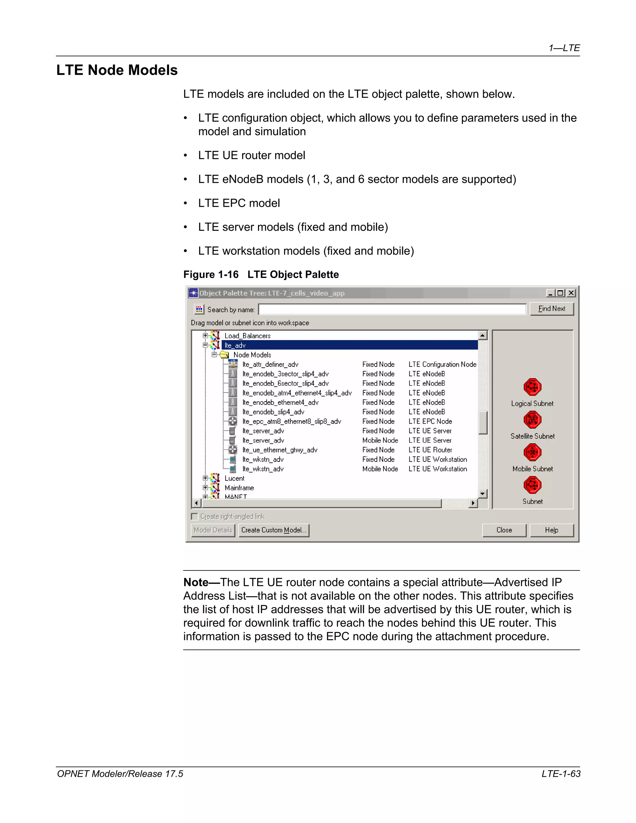
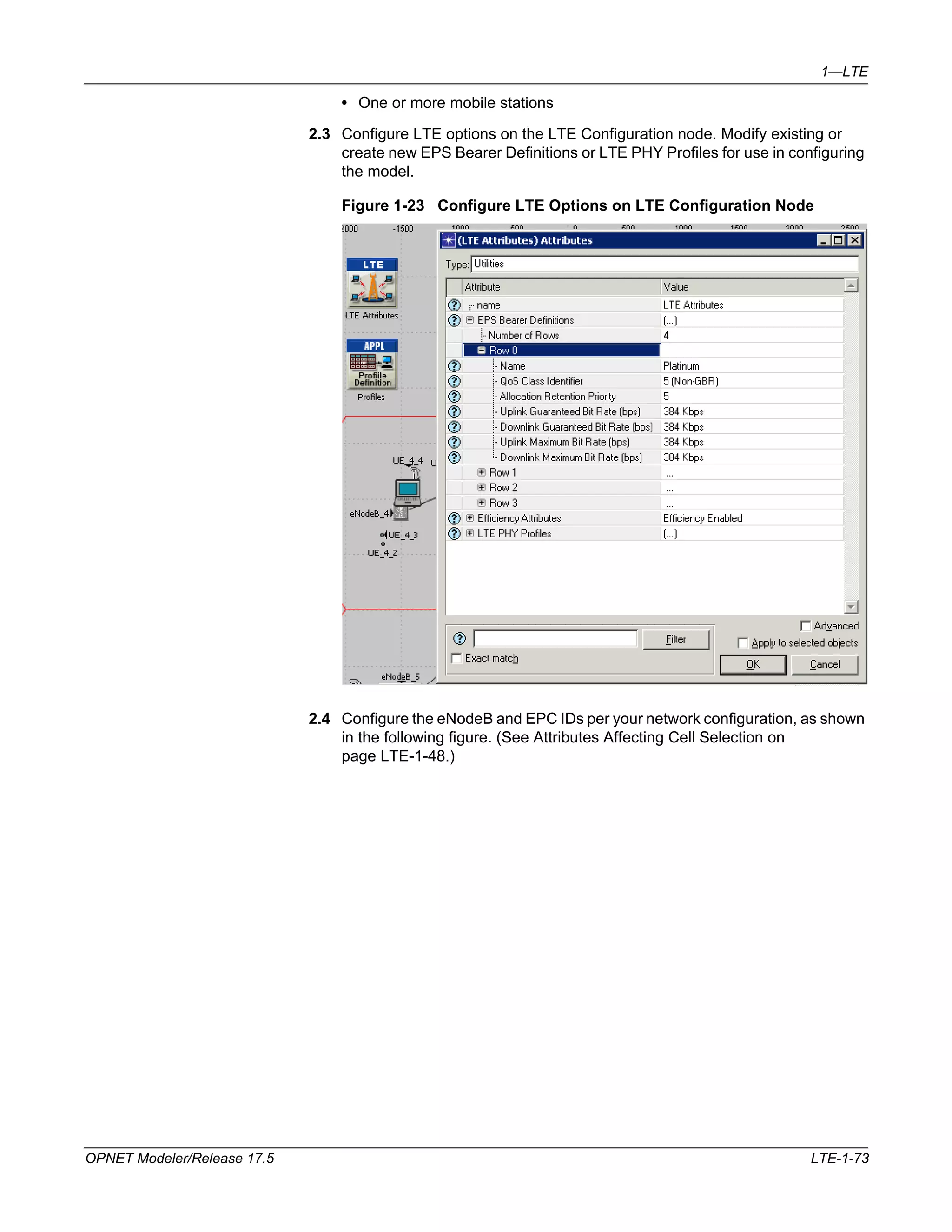
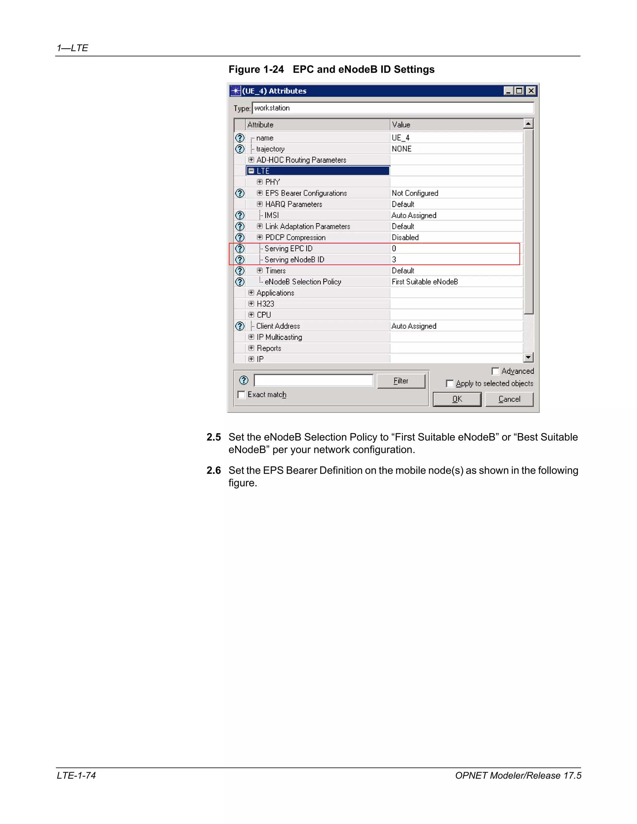
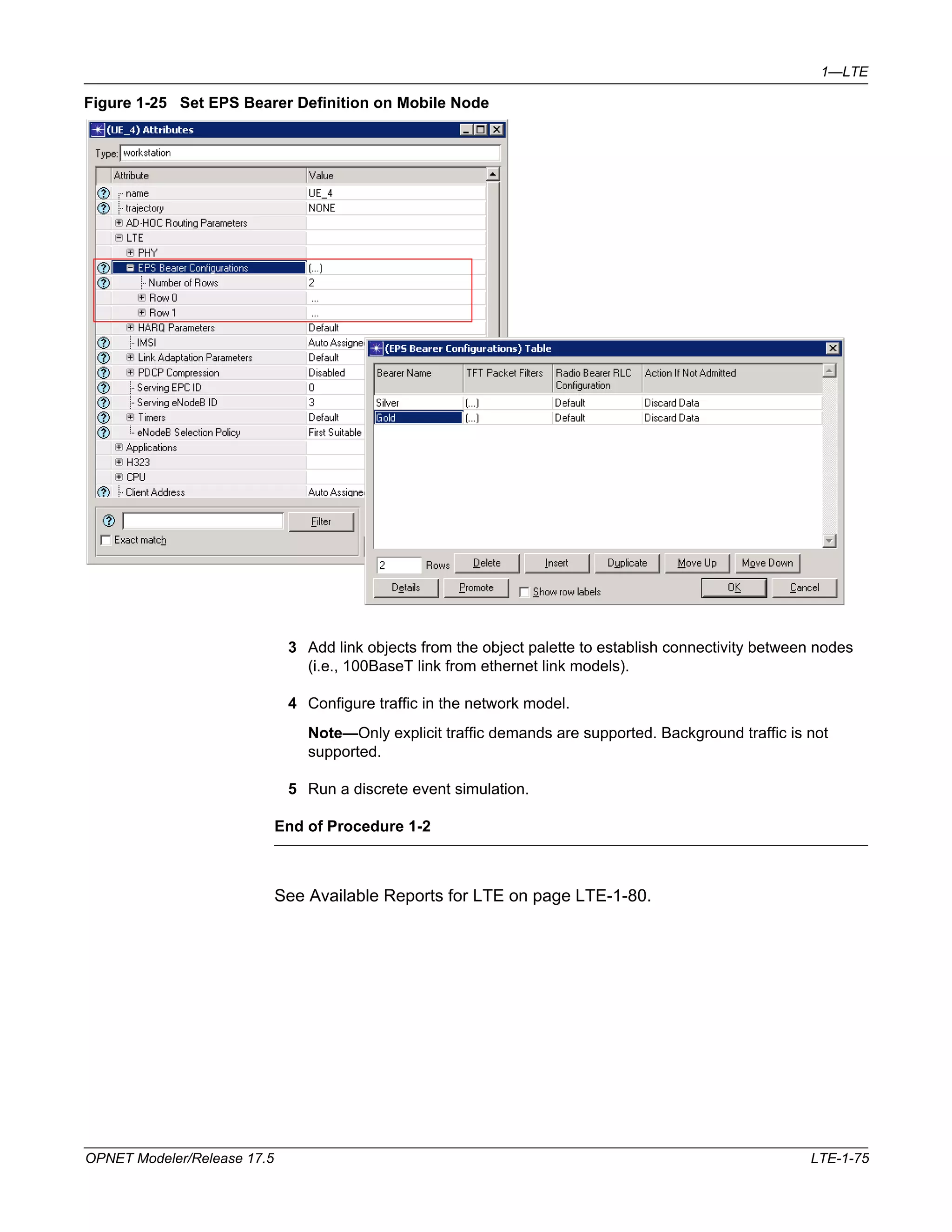
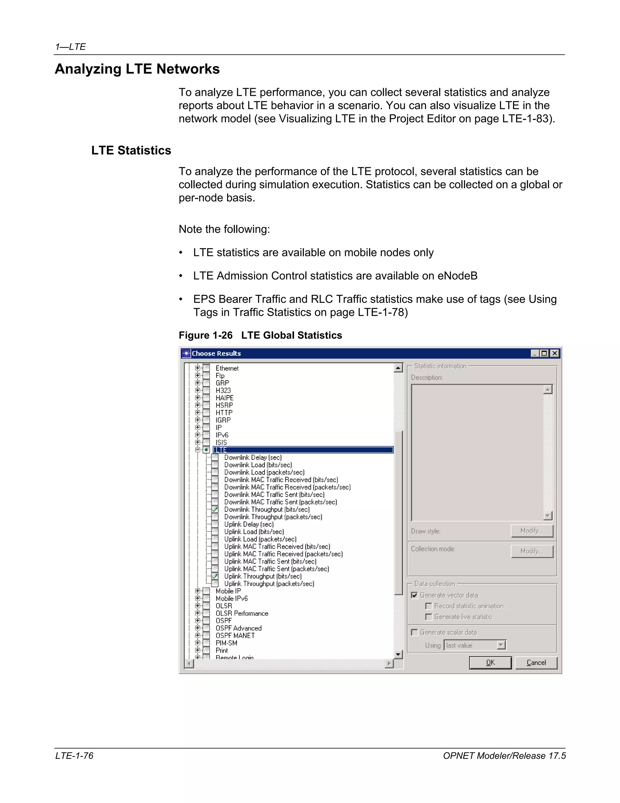
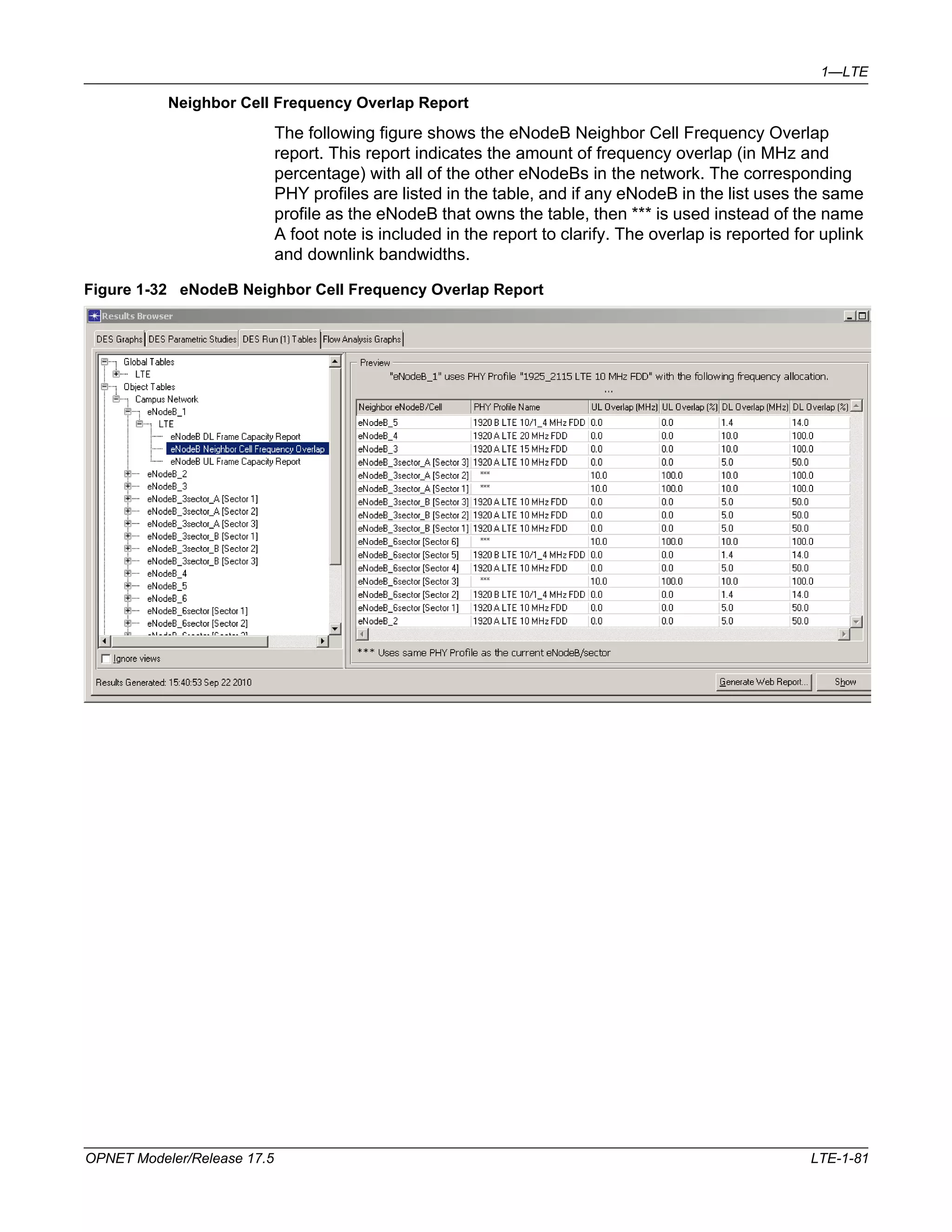
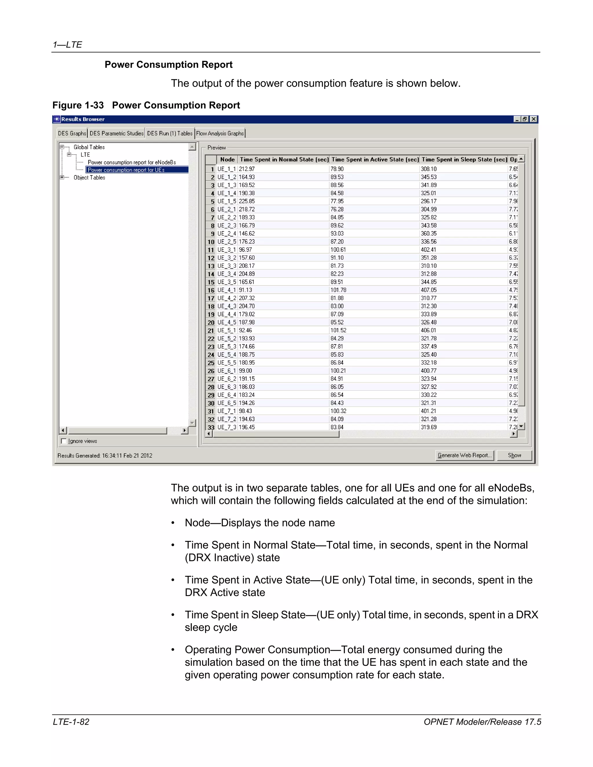
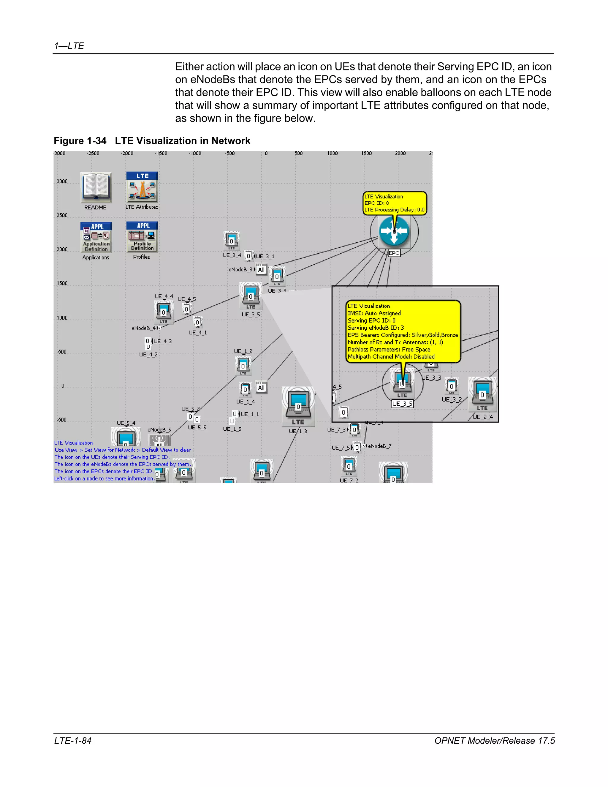

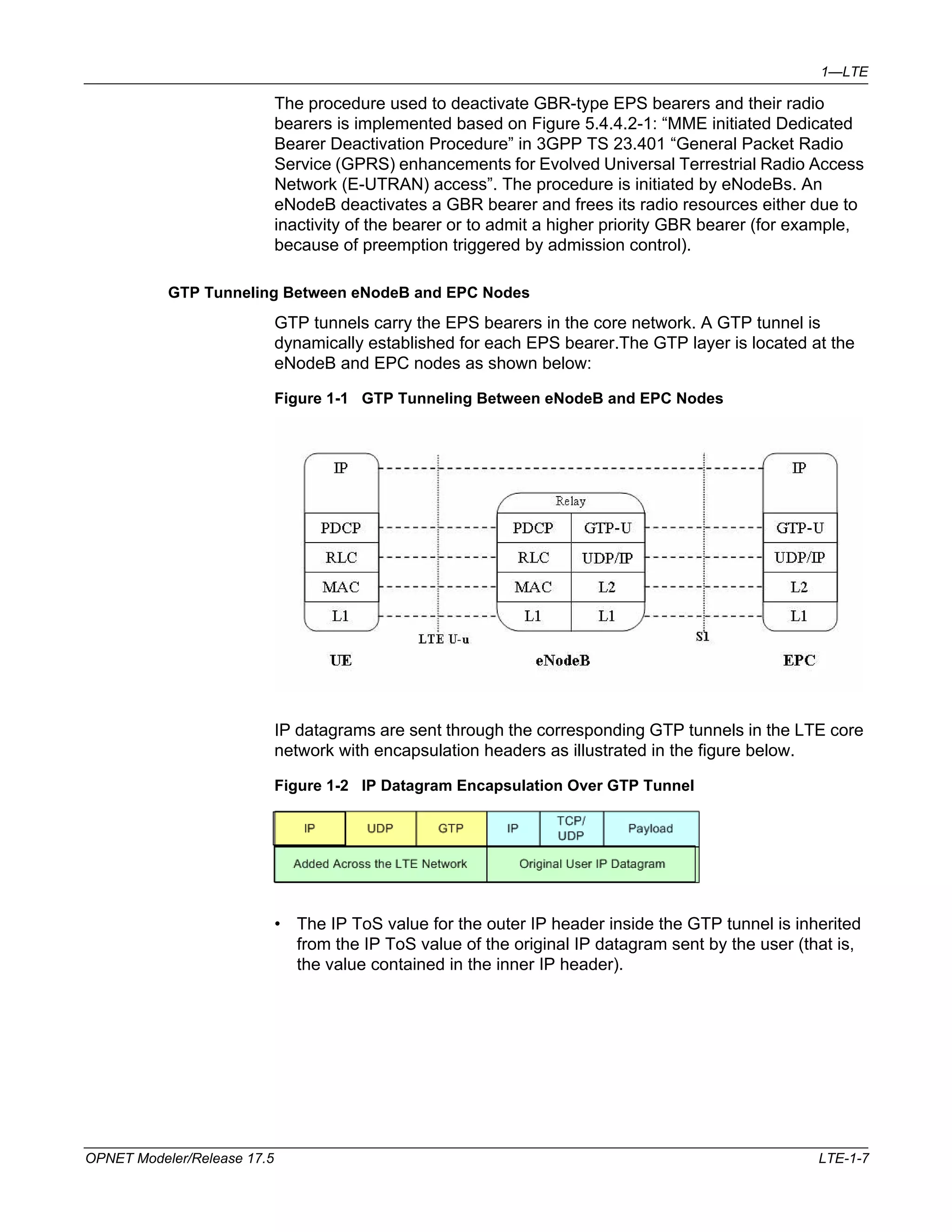
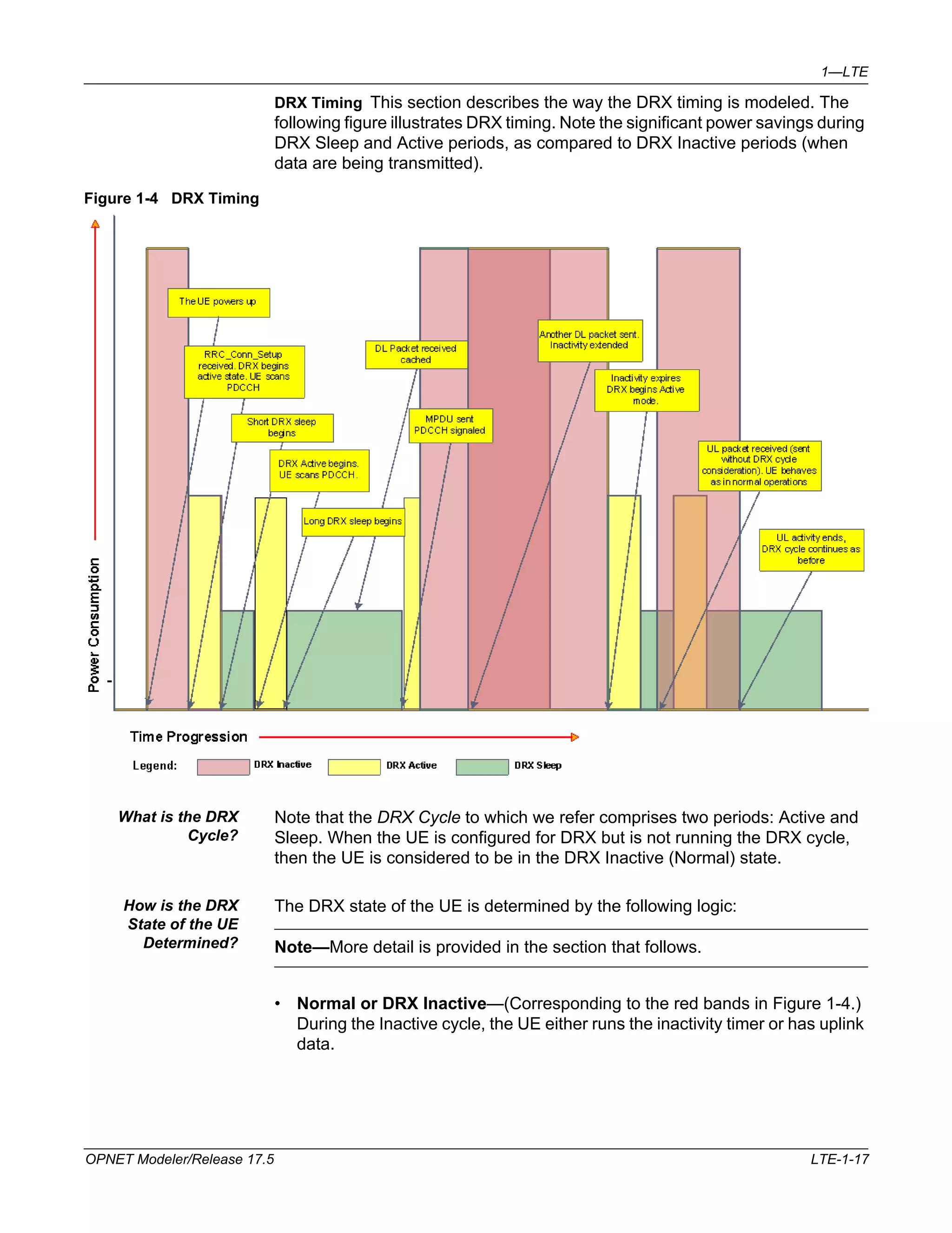
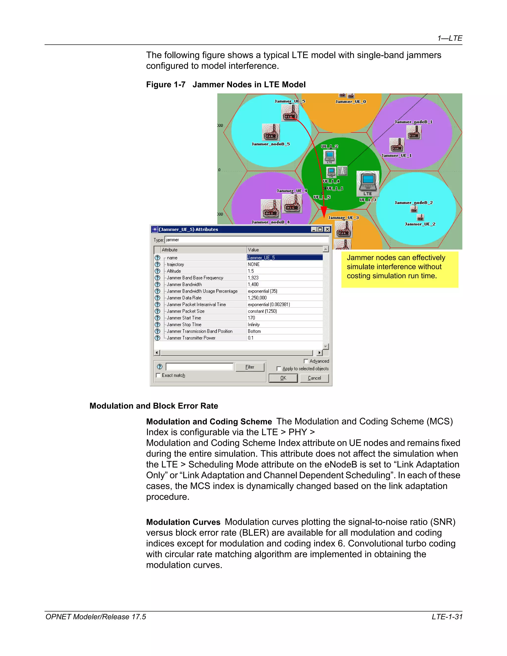
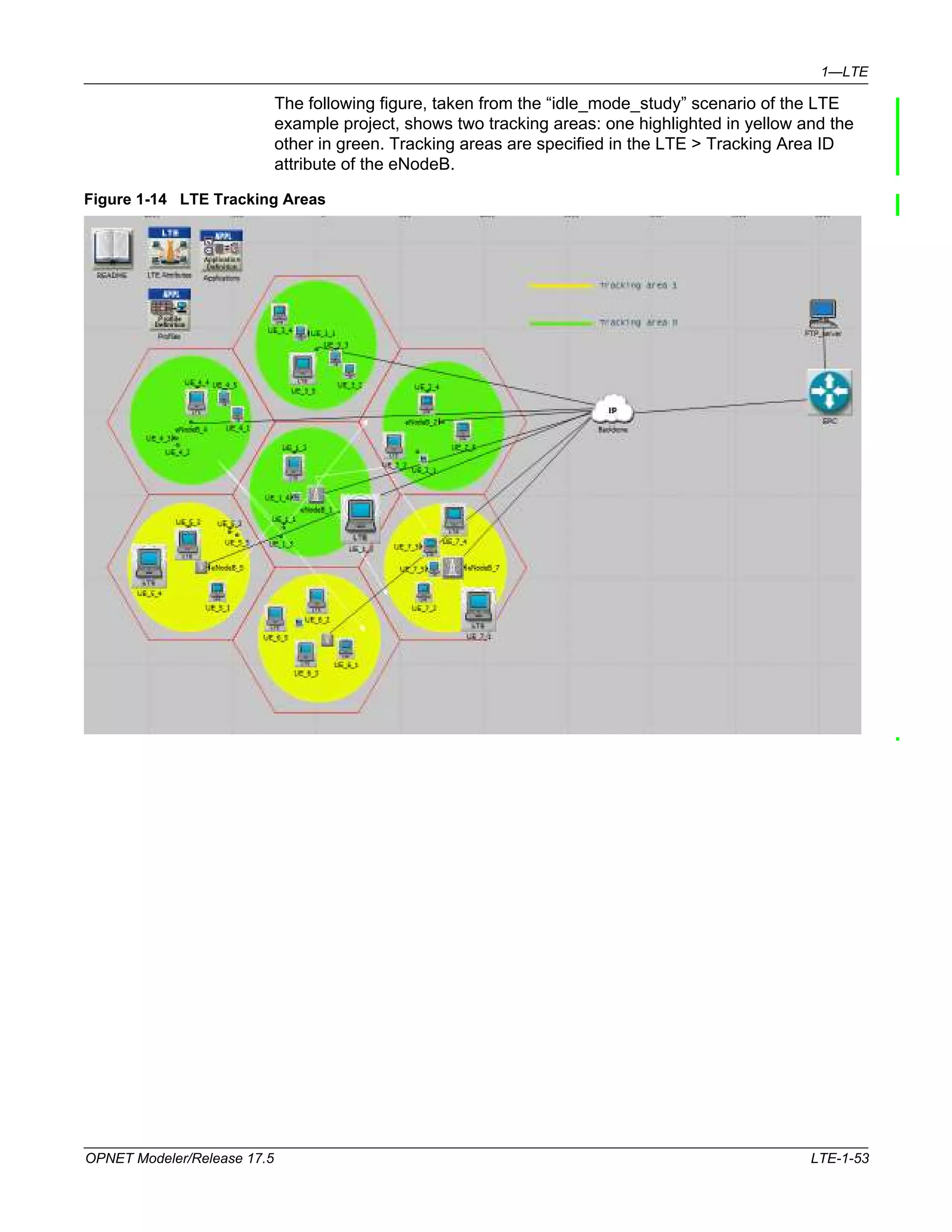
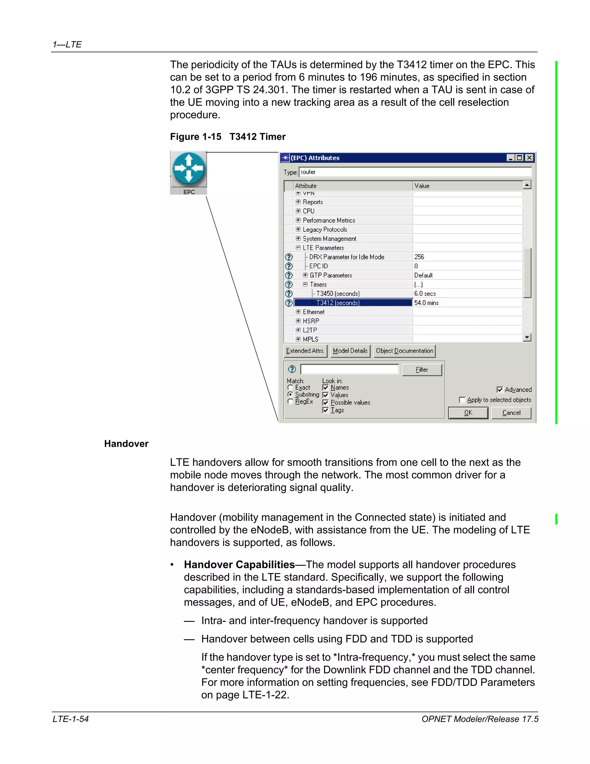
Long Term Evolution (LTE) is an all-IP wireless protocol that provides increased data rates and improved user response times compared to previous standards. The LTE model simulates key aspects of LTE including EPS bearers, traffic flow classification, session management, broadcast/multicast traffic using MBMS, and protocol layers like PDCP, RLC, MAC and the physical layer for both FDD and TDD schemes. Configuration and analysis of LTE networks is also supported.