LTE and LTE-Advanced are cellular communication standards that provide higher data speeds and improved network performance over previous standards. Key points:
- LTE was developed as an upgrade to 3G UMTS networks by 3GPP to support higher data rates and lower latency.
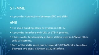
- The LTE architecture uses E-UTRAN base stations (eNodeBs) connected to an Evolved Packet Core (EPC) via an S1 interface.
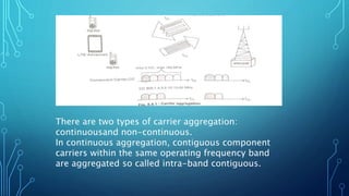
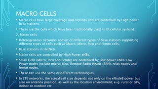
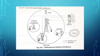
- LTE-Advanced further improves LTE capabilities through carrier aggregation, advanced MIMO techniques, and support for relay nodes to enhance coverage.