Downloaded 690 times

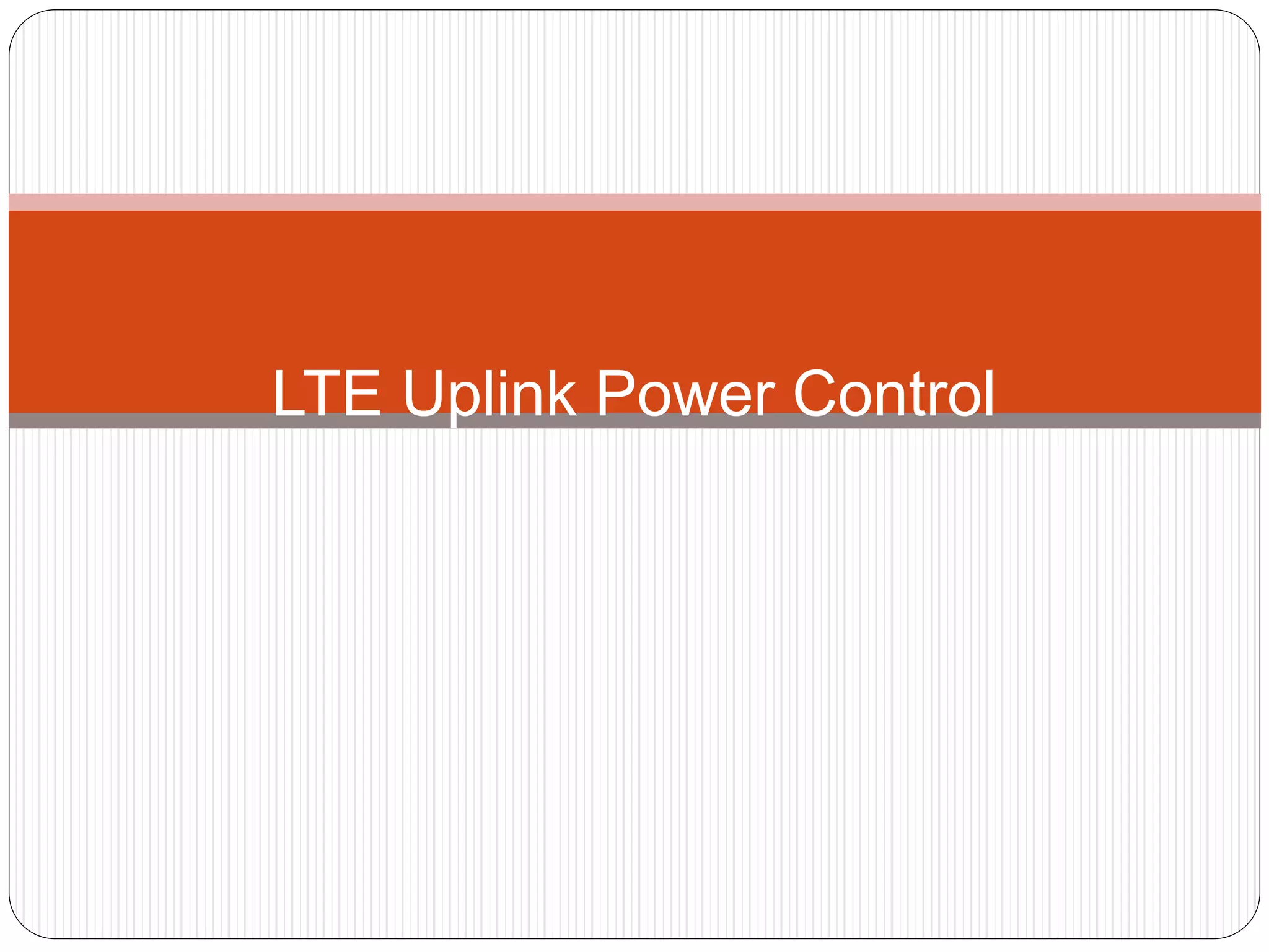
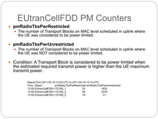
![referenceSignalPower
Downlink reference-signal EPRE (Energy Per
Resource Element).
Why 21dBm?
10MHz LTE carrier -> 50 RB
1 RB = 12 sub carriers (12 symbols)
Assuming 40W RDLT, then 40 [W]/50 [RB]= 0.8 [W/RB]
Pwr per symbol = 0.8 [W]/12 [symbols] = 0.0667 [W]/[symbol]
0.0667 [W] = 18.24 [dBm]
2 TX antennas = 18.24 [dBm] + 3 [dB] = 21.24 [dBm]
“The downlink reference-signal EPRE can be derived from the downlink reference-signal transmit
power given by the parameter Reference-signal-power provided by higher layers. The downlink
reference-signal transmit power is defined as the linear average over the power contributions (in
[W]) of all resource elements that carry cell-specific reference signals within the operating system
bandwidth.”(2x2 MIMO: 4 RS out of 14 in every 3rd sub-carrier 9.6% of total
power 46dBm)](https://image.slidesharecdn.com/ltepowercontrol-160928142150/85/Lte-power-control-8-320.jpg)
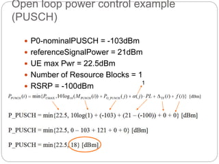
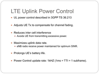
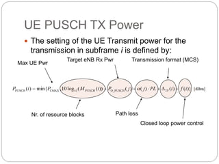
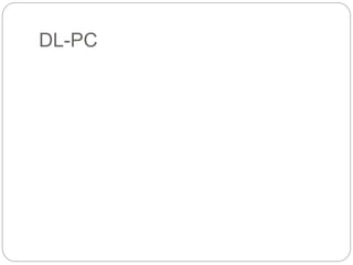
![UL Power control (PUSCH) – Open
loop
UE transmit power for PUSCH transmission:
is the maximum allowable UE power;
M is the number of scheduled resource blocks; (broadcasted on PDCCH)
PL is the downlink pathloss, estimated by UE. The UE can use
measurements of DL pathloss for estimation of UL pathloss. (Open-
loop)
is to enable fractional pathloss compensation;
PO_PUSCH set according to SINRtarget. SINRtarget is a parameter set to fulfill
the HARQ operating Point (OPP) quality requirements using the most
efficient MCS. PO_PUSCH is broadcasted on BCCH SIB2
is a Transport Format (TF) specific offset.
][)}(log10,min{ TFO_PUSCH10MAXPUSCH dBmifPLPMPP
O_UE_PUSCHPUSCHO_NOMINAL__
argarg_ )1(
PPP
NSINRPSDP
PUSCHO
ettetRXtPUSCHO
TF
MAXP](https://image.slidesharecdn.com/ltepowercontrol-160928142150/85/Lte-power-control-11-320.jpg)
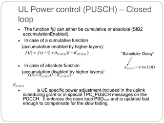
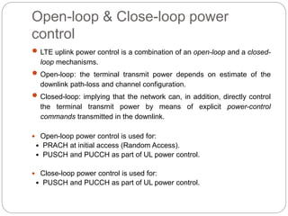
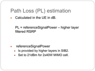
![PUSCH
PUSCHTPC Command
Accumulated
[dB]
Absolute [dB]
0 -1 -4
1 0 -1
2 1 1
3 3 4
UL Power control (PUSCH) – Closed
loop
PUSCH
is set according to:](https://image.slidesharecdn.com/ltepowercontrol-160928142150/85/Lte-power-control-13-320.jpg)
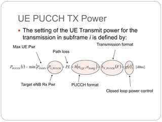
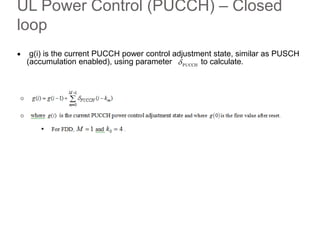
![UL Power Control (PUCCH) – Open
loop
UE transmit power for PUCCH transmission:
is the maximum allowable UE power;
PL is the downlink pathloss, estimated by UE. The UE can use
measurements of DL pathloss for estimation of UL pathloss. (Open-
loop)
h(n) is a PUCCH format dependent value where n(cqi) corresponds to
the number of information bits for the CQI, and n(harq) the number of
HARQ bits. For PUCCH formats 1, 1a and 1b, h(n) is always 0. For
PUCCH format 2, h(n) is 0 for normal cyclic prefix and n(cqi)<4, but
may take on other values with extended cyclic prefix or for n(cqi)>4.
corresponds to a PUCCH format offset. Provided by
higher layers.
][)}()(),(,min{ F_PUCCHO_PUCCHMAXPUCCH dBmigFnnhPLPPP harqcqi
)(_ FPUCCHF
MAXP](https://image.slidesharecdn.com/ltepowercontrol-160928142150/85/Lte-power-control-14-320.jpg)
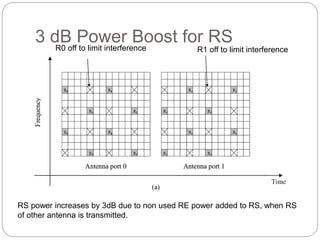
![UL Power Control (PUCCH) – Closed
loop
PUCCHTPC Command Accumulated [dB]
0 -1
1 0
2 1
3 3
The open loop part controls PO_PUCCH, and the closed loop part controls g(i). This
function works much the same way as for PUSCH, except the TPC commands
for PUCCH can be transmitted in the downlink scheduling assignments, and
w i t h o u t a n y u p l i n k g r a n t .](https://image.slidesharecdn.com/ltepowercontrol-160928142150/85/Lte-power-control-16-320.jpg)
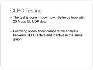
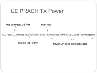
![EUtranCellFDD PM Counters
pmRadioRecInterferencePwr
The measured Noise and Interference Power on PUSCH, according to 36.214
PDF ranges:
[0]: N+I <= -121
[1]: -121 < N+I <= -120
[2]: -120 < N+I <= -119
[3]: -119 < N+I <= -118
[4]: -118 < N+I <= -117
[5]: -117 < N+I <= -116
[6]: -116 < N+I <= -115
[7]: -115 < N+I <= -114
[8]: -114< N+I <= -113
[9]: -113 < N+I <= -112
[10]: -112 < N+I <= -108
[11]: -108 < N+I <= -104
[12]: -104 < N+I <= -100
[13]: -100 < N+I <= -96
[14]: -96 < N+I <= -92
[15]: -92 < N+I
Condition: An average value is measured on a TTI basis
Unit: dBm/PRB
Report from 2011-02-16 14:00 UTC to 2011-02-16 14:14 UTC
Time Object pmRadioRecInterferencePwr
14:00 EUtranCellFDD=172169_1 5664,880660,8739,3020,1372,364,21,0,0,0,0,0,0,0,0,0
14:00 EUtranCellFDD=172169_2 617247,282277,309,7,0,0,0,0,0,0,0,0,0,0,0,0
14:00 EUtranCellFDD=172169_3 761490,138350,0,0,0,0,0,0,0,0,0,0,0,0,0,0](https://image.slidesharecdn.com/ltepowercontrol-160928142150/85/Lte-power-control-22-320.jpg)


The document discusses LTE uplink power control. It describes that uplink power control uses both open-loop and closed-loop mechanisms. Open-loop power control estimates path loss to set the initial transmission power, while closed-loop allows the network to directly control transmission power through power control commands. Power control helps reduce interference, maximize data rates, and prolong UE battery life by adjusting transmission power on a subframe basis.


![Getting Started with Apache Spark: Big Data Made Simple [Free Meetup]](https://cdn.slidesharecdn.com/ss_thumbnails/apachesparkgettingstarted-260203175547-8361bcc3-thumbnail.jpg?width=640&height=640&fit=bounds)


