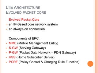
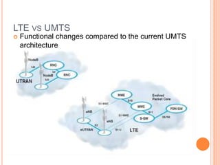
LONG TERM EVOLUTION 
Reporters: 
Michael Pablo Dela Paz Mark Anthony Juanillo 
Carlo Bonne Matienzo Neo Gabriel Pablo
UMTS 
 Universal Mobile Telecommunications System (UMTS) 
 UMTS is an upgrade from GSM via GPRS or EDGE 
 The standardization work for UMTS is carried out by Third 
Generation Partnership Project (3GPP) 
 Data rates of UMTS are: 
 144 kbps for rural 
 384 kbps for urban outdoor 
 2048 kbps for indoor and low range outdoor 
 Virtual Home Environment (VHE)
UMTS FREQUENCY SPECTRUM 
 UMTS Band 
 1900-2025 MHz and 2110-2200 MHz for 3G 
transmission 
 In the US, 1710–1755 MHz and 2110– 
2155 MHz will be used instead, as the 1900 MHz 
band was already used.
UMTS FREQUENCY SPECTRUM
UMTS NETWORK ARCHITECTURE 
 UMTS network architecture consists of three 
domains: 
 Core Network (CN) 
 Provide switching, routing and transit for user traffic 
 UMTS Terrestrial Radio Access Network (UTRAN) 
 Provides the air interface access method for user equipment. 
 User Equipment (UE) 
 Terminals work as air interface counterpart for base stations.
UMTS ARCHITECTURE
3.5G (HSPA) 
High Speed Packet Access (HSPA) is the combination of 
two mobile telephony protocols; 
High Speed Downlink Packet Access (HSDPA) and 
High Speed Uplink Packet Access (HSUPA), 
that extends and improves the performance of existing 
WCDMA protocols 
3.5G introduces many new features that will enhance the 
UMTS technology in future. 
These include: 
- Adaptive Modulation and Coding 
- Fast Scheduling 
- Backward compatibility with 3G 
- Enhanced Air Interface
WHAT IS LTE ?? 
 LTE stands for Long Term Evolution 
 Next Generation mobile broadband technology 
 Promises data transfer rates of 100 Mbps 
 Based on UMTS 3G technology 
 Optimized for All-IP traffic
MOTIVATION FOR LTE 
 Need for optimised system 
• Evolve UMTS towards packet only system 
 Need for higher data rates 
• Can be achieved with HSDPA/HSUPA 
• And/or new air interface defined by 3GPP LTE 
 Need for high quality of service 
• Use of licensed frequencies to guarantee quality of services 
• Always-on experience (reduce control plane latency 
significantly) 
• Reduce round trip delay 
 Need for cheaper infrastructure 
• Simply architecture, reduce number of network elements 
• Most data users are less mobile
ADVANTAGES OF LTE
COMPARISON OF LTE SPEED
LTE ARCHITECTURE 
LTE Architecture mainly consists of 3 Main 
Components: 
 Evolved Packet Core (EPC) 
 User Equipment (UE) 
 E-UTRAN - Evolved UMTS Terrestrial Radio 
Access Network.
LTE ARCHITECTURE 
EVOLVED PACKET CORE 
Evolved Packet Core 
 an IP-Based core network system 
 an always-on connection 
Components of EPC: 
 MME (Mobile Management Entity) 
 S-GW (Serving Gateway) 
 P-GW (Packet Data Network – PDN Gateway) 
 HSS (Home Subscriber Server) 
 PCRF (Policy Control & Charging Rule Function)
LTE ARCHITECTURE 
EVOLVED PACKET CORE 
Mobile Management Entity (MME) 
 responsible for Establishment & Releasing of 
connection between the user and packet core 
network 
 handles Mobility management like location 
registration, authentication, handover with HSS. 
Serving Gateway (S-GW) 
 acts as Router, forward & receive data between 
Wireless Base Station eNodeb or 3GPP access 
networks such as 2G / 3G & the PDN Gateways 
 for roaming, the S-GW & P-GW provides 
boundaries between operators
LTE ARCHITECTURE 
EVOLVED PACKET CORE 
Packet Data Network – PDN Gateway (P-GW) 
 communicates with outside world using SGi interface. Each 
PDN is identified by an Access Point Name (APN). 
 functions include IP Address Assignment to Terminals, User 
Authentication, QoS (Quality of Service) Control, Charging 
Data (as per PCRF), 
 capable of Deep Packet Inspection (DPI) - Involves either to 
Pass or Drop the User Data Packet.
LTE ARCHITECTURE 
EVOLVED PACKET CORE 
Home Subscriber Server (HSS) 
 Its like HLR (Home Location Register), Its a Central 
Database, contains all information about all network 
operator's subscriber. 
Policy Control & Charging Rule Function (PCRF) 
 responsible for Policy Control Decision Making. 
 function as to either accept or reject data packets 
 check the charging method from users & instruct 
S/P-GW & Access Network to work accordingly.
LTE ARCHITECTURE 
USER EQUIPMENT 
User Equipment (UE) 
Its the same as the mobile equipment used in UMTS 
& GSM Network. 
It contains following modules: 
 Mobile Equipment (ME) - handles all Communication 
functions. 
 Terminal Equipment (TE) - terminates the Data 
Stream. 
 Universal Integrated Circuit Card (UICC) - Also known 
as SIM Card, which stores user specific data, like home 
network identity, security keys, user's phone number.
LTE ARCHITECTURE 
EVOLVED UMTS TERRESTRIAL RADIO ACCESS 
NETWORK. 
E-UTRAN (the Access Network) 
 handles all the Radio Communications between 
Mobile & EPC. 
 provides Higher Data Rates, Lower Latency & 
Specifically designed for Packet Data. 
It has just one component Evolved Base Station 
called eNodeB or eNB, which interfaces with UE. 
Each eNB is a Base Station that controls mobiles in 
one or more cells.
LTE ARCHITECTURE
MAJOR LTE RADIO TECHNOLOGIES 
 Uses Orthogonal Frequency Division Multiplexing 
(OFDM) for downlink 
 Uses Single Carrier Frequency Division Multiple Access 
(SC-FDMA) for uplink 
 Uses Multi-input Multi-output(MIMO) for enhanced 
throughput 
 Reduced power consumption 
 Higher RF power amplifier efficiency (less battery power 
used by handsets)
ANTENNA TECHNIQUES
LTE VS UMTS 
 Functional changes compared to the current UMTS 
architecture

Long Term Evolution

  • 1.
    LONG TERM EVOLUTION Reporters: Michael Pablo Dela Paz Mark Anthony Juanillo Carlo Bonne Matienzo Neo Gabriel Pablo
  • 2.
    UMTS  UniversalMobile Telecommunications System (UMTS)  UMTS is an upgrade from GSM via GPRS or EDGE  The standardization work for UMTS is carried out by Third Generation Partnership Project (3GPP)  Data rates of UMTS are:  144 kbps for rural  384 kbps for urban outdoor  2048 kbps for indoor and low range outdoor  Virtual Home Environment (VHE)
  • 3.
    UMTS FREQUENCY SPECTRUM  UMTS Band  1900-2025 MHz and 2110-2200 MHz for 3G transmission  In the US, 1710–1755 MHz and 2110– 2155 MHz will be used instead, as the 1900 MHz band was already used.
  • 4.
  • 5.
    UMTS NETWORK ARCHITECTURE  UMTS network architecture consists of three domains:  Core Network (CN)  Provide switching, routing and transit for user traffic  UMTS Terrestrial Radio Access Network (UTRAN)  Provides the air interface access method for user equipment.  User Equipment (UE)  Terminals work as air interface counterpart for base stations.
  • 6.
  • 7.
    3.5G (HSPA) HighSpeed Packet Access (HSPA) is the combination of two mobile telephony protocols; High Speed Downlink Packet Access (HSDPA) and High Speed Uplink Packet Access (HSUPA), that extends and improves the performance of existing WCDMA protocols 3.5G introduces many new features that will enhance the UMTS technology in future. These include: - Adaptive Modulation and Coding - Fast Scheduling - Backward compatibility with 3G - Enhanced Air Interface
  • 8.
    WHAT IS LTE??  LTE stands for Long Term Evolution  Next Generation mobile broadband technology  Promises data transfer rates of 100 Mbps  Based on UMTS 3G technology  Optimized for All-IP traffic
  • 9.
    MOTIVATION FOR LTE  Need for optimised system • Evolve UMTS towards packet only system  Need for higher data rates • Can be achieved with HSDPA/HSUPA • And/or new air interface defined by 3GPP LTE  Need for high quality of service • Use of licensed frequencies to guarantee quality of services • Always-on experience (reduce control plane latency significantly) • Reduce round trip delay  Need for cheaper infrastructure • Simply architecture, reduce number of network elements • Most data users are less mobile
  • 10.
  • 11.
  • 12.
    LTE ARCHITECTURE LTEArchitecture mainly consists of 3 Main Components:  Evolved Packet Core (EPC)  User Equipment (UE)  E-UTRAN - Evolved UMTS Terrestrial Radio Access Network.
  • 13.
    LTE ARCHITECTURE EVOLVEDPACKET CORE Evolved Packet Core  an IP-Based core network system  an always-on connection Components of EPC:  MME (Mobile Management Entity)  S-GW (Serving Gateway)  P-GW (Packet Data Network – PDN Gateway)  HSS (Home Subscriber Server)  PCRF (Policy Control & Charging Rule Function)
  • 14.
    LTE ARCHITECTURE EVOLVEDPACKET CORE Mobile Management Entity (MME)  responsible for Establishment & Releasing of connection between the user and packet core network  handles Mobility management like location registration, authentication, handover with HSS. Serving Gateway (S-GW)  acts as Router, forward & receive data between Wireless Base Station eNodeb or 3GPP access networks such as 2G / 3G & the PDN Gateways  for roaming, the S-GW & P-GW provides boundaries between operators
  • 15.
    LTE ARCHITECTURE EVOLVEDPACKET CORE Packet Data Network – PDN Gateway (P-GW)  communicates with outside world using SGi interface. Each PDN is identified by an Access Point Name (APN).  functions include IP Address Assignment to Terminals, User Authentication, QoS (Quality of Service) Control, Charging Data (as per PCRF),  capable of Deep Packet Inspection (DPI) - Involves either to Pass or Drop the User Data Packet.
  • 16.
    LTE ARCHITECTURE EVOLVEDPACKET CORE Home Subscriber Server (HSS)  Its like HLR (Home Location Register), Its a Central Database, contains all information about all network operator's subscriber. Policy Control & Charging Rule Function (PCRF)  responsible for Policy Control Decision Making.  function as to either accept or reject data packets  check the charging method from users & instruct S/P-GW & Access Network to work accordingly.
  • 17.
    LTE ARCHITECTURE USEREQUIPMENT User Equipment (UE) Its the same as the mobile equipment used in UMTS & GSM Network. It contains following modules:  Mobile Equipment (ME) - handles all Communication functions.  Terminal Equipment (TE) - terminates the Data Stream.  Universal Integrated Circuit Card (UICC) - Also known as SIM Card, which stores user specific data, like home network identity, security keys, user's phone number.
  • 18.
    LTE ARCHITECTURE EVOLVEDUMTS TERRESTRIAL RADIO ACCESS NETWORK. E-UTRAN (the Access Network)  handles all the Radio Communications between Mobile & EPC.  provides Higher Data Rates, Lower Latency & Specifically designed for Packet Data. It has just one component Evolved Base Station called eNodeB or eNB, which interfaces with UE. Each eNB is a Base Station that controls mobiles in one or more cells.
  • 19.
  • 20.
    MAJOR LTE RADIOTECHNOLOGIES  Uses Orthogonal Frequency Division Multiplexing (OFDM) for downlink  Uses Single Carrier Frequency Division Multiple Access (SC-FDMA) for uplink  Uses Multi-input Multi-output(MIMO) for enhanced throughput  Reduced power consumption  Higher RF power amplifier efficiency (less battery power used by handsets)
  • 21.
  • 22.
    LTE VS UMTS  Functional changes compared to the current UMTS architecture

Editor's Notes

  • #23 3G operators have already experienced difficulties in coping with data-hungry smart phones that saturate the network and can prevent subscribers from making voice calls. LTE promotes an even richer and more diverse mix of subscriber services – including voice, video, web browsing, e-mail and social networking – that will have very different data traffic profiles and therefore impact the network performance in a way that is difficult to predict. This is much more difficult to test than for 2G networks like GSM, where the bulk of traffic is centred on voice and SMS. At the same time, compared to UMTS, the LTE standard has removed the Radio Network Controller (RNC) that was a governing element in the UMTS Radio Access Network (UTRAN). This was traditionally used as the access point into the 3G network for high capacity testing, so it becomes necessary to test over the air interface. For 2G and 3G networks, some operators adopted the ‘wall of phones’ approach for end-to-end testing into the NodeB in the UTRAN, but due to the larger number of UEs per cell that LTE supports, along with the increased service complexity and feature churn, this becomes impractical. Figure 2 shows a comparison of the UTRAN with the LTE network architecture. As mentioned above, the LTE network has been simplified compared to 3G UTRAN with the removal of the RNC node. This simplification of the network has concentrated more functionality into the eNodeB base station, which can now communicate directly with other eNBs to handle functionality such as device handover between base stations. A flatter network architecture leads to improved data latency (the transmission delay between the transmitter sending data and the receiver receiving it) and better support of delay-sensitive, interactive and real-time communications.