Downloaded 437 times

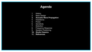

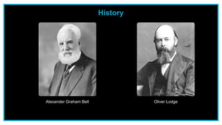

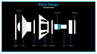
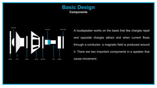
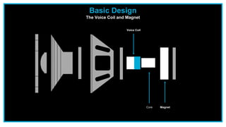
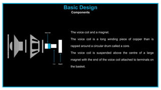


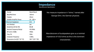
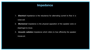


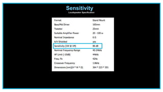


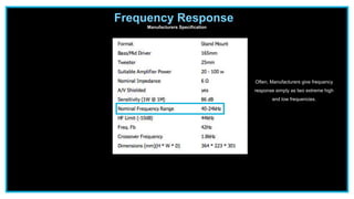


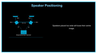

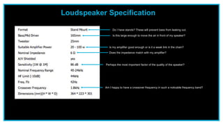

The document provides an overview of loudspeakers, including their history, basic design, acoustic wave propagation, impedance, power, sensitivity, distortion, frequency response, speaker positioning, and some studio classics. It discusses how a loudspeaker works based on the voice coil and magnet creating a magnetic field. Impedance is described as the opposition to electric current flow and how manufacturers specify nominal impedance. Crossovers are explained as either passive or active systems to separate signal frequencies sent to individual drivers. Common studio monitors are also highlighted.


![Acoustics [Microphones]](https://cdn.slidesharecdn.com/ss_thumbnails/acousticsfinalfinal-190716163521-thumbnail.jpg?width=640&height=640&fit=bounds)