Download to read offline


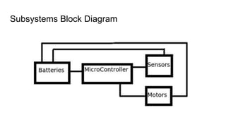
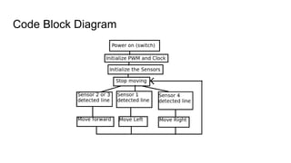
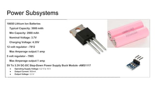
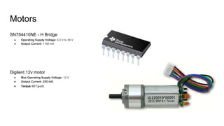
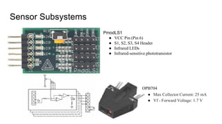
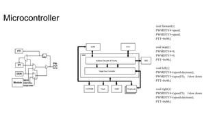
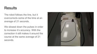

This document summarizes the subsystems of a line following robot, including its power system using lithium ion batteries and voltage regulators, motors controlled by an H-bridge circuit, line-sensing sensors, and microcontroller code for moving the robot forward, backward, and turning. It describes the results of testing where the robot initially overcorrected when following the line but increasing accuracy after slowing the motor pulses. The conclusion reflects on the challenges of the project and designing an affordable learning platform.