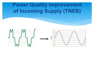
Power Quality Improvement
of Incoming Supply (TNEB)
 Steps planned to Improve Power Quality:
 1. Install HT AVR to ensure Voltage variation within ±1%.

 2. Install UPS to reduce losses due to Power Brown outs &
Black
 outs (M/c Breakdown, Tool Breakdown etc.).

 3. Upgrade the Voltage from 11KV to 33KV.
Steps Planned to Improve Power
Quality
• Failure of Motor windings in Heat Treatment Machines due to
 Low voltage (VHF, SQF etc.,).

• Imported CNC,PLC M/c’s fails to run without coolant pump due to
 voltage fluctuation.
• lights are flickering and capacitors burst due to low voltage.
• Frequent tripping of Circuit breakers due to low voltage during
 full load.
• Frequent tripping of Air conditioner and compressors due to
 voltage fluctuation.
Problems occurred before
installing AVR
AVR Installation
Before
After
Incoming
supply
(TNEB)
VCB 2
Bus bar
Tr-1 Tr-2 Tr-3 Tr-4
Load LoadLoadLoad
Tr-1 Tr-2 Tr-3 Tr-4
Load LoadLoadLoad
Bus bar
VCB 2
VCB 1
Incoming
supply (TNEB)
6.3 MVA
AVR
Additionally
Inserted
AVR system installed
Voltage stabilization process in
LT side
Input voltage to AVR : 9000V to 12000V
Output voltage from AVR : 11000V ± 1% (10890V to 11110V)
Stabilization process : HT voltage LT voltage
conventional : 9000V to 12000V 340V to 470V
Recommended : 11000V±1% 415V±6%
(i.e.390V
to 440V)
By AVR : 11000V±1% 410V to 420V
voltage bandwidth for motors
D
GOOD
ALLOWED
DANGEROUS
410
V
420
V
390
V
440
V
340
V
470
V
Voltage Bandwidth
Voltage in LT before & after
installation of AVRVoltage in LT side
0
50
100
150
200
250
300
350
400
450
500
8
A
.M
.
1
0
A
.M
.
1
2
P
.M
.2
P
.M
.4
P
.M
.6
P
.M
.8
P
.M
.
1
0
P
.M
.
1
2
A
.M
.2
A
.M
.4
A
.M
.6
A
.M
.
Time
Voltage
Before After Required
After installation of AVR
Avoided M/c brownouts, blackouts due to voltage variation.
Avoided failure of Motor winding and CNC M/c down time due
to voltage fluctuation.
Avoided failure of lights and fans due to low voltage.
Avoided tripping of Air conditioner and compressors due to under
voltage.
Up gradation of voltage from 11 KV
to 33 KV
6.3 MVA
AVR
33 KV TNEB
SUPPLY
RMG 33 KV
VCB
6.3 MVA,33KV / 11KV
TRANSFORMER
11 KV VCB
VCB
VCB VCB VCB
To
Power House
To
DI building
To
E & D
Increasing the Capacity of UPS
Bus bar
Tr-1 Tr-2 Tr-3 Tr-4
Load Load
Load
160 KVA
Existing
160 KVA 550 KVA 160 KVA
Load
Existing Capacity
Rotary = 870 KVA
UPCR = 160 KVA
Planned Capacity
Rotary = 2360KVA
UPCR = 320 KVA
Thank You…

sujesh

  • 1.
    Power Quality Improvement ofIncoming Supply (TNEB)
  • 2.
     Steps plannedto Improve Power Quality:  1. Install HT AVR to ensure Voltage variation within ±1%.   2. Install UPS to reduce losses due to Power Brown outs & Black  outs (M/c Breakdown, Tool Breakdown etc.).   3. Upgrade the Voltage from 11KV to 33KV. Steps Planned to Improve Power Quality
  • 3.
    • Failure ofMotor windings in Heat Treatment Machines due to  Low voltage (VHF, SQF etc.,).  • Imported CNC,PLC M/c’s fails to run without coolant pump due to  voltage fluctuation. • lights are flickering and capacitors burst due to low voltage. • Frequent tripping of Circuit breakers due to low voltage during  full load. • Frequent tripping of Air conditioner and compressors due to  voltage fluctuation. Problems occurred before installing AVR
  • 4.
    AVR Installation Before After Incoming supply (TNEB) VCB 2 Busbar Tr-1 Tr-2 Tr-3 Tr-4 Load LoadLoadLoad Tr-1 Tr-2 Tr-3 Tr-4 Load LoadLoadLoad Bus bar VCB 2 VCB 1 Incoming supply (TNEB) 6.3 MVA AVR Additionally Inserted
  • 5.
  • 6.
    Voltage stabilization processin LT side Input voltage to AVR : 9000V to 12000V Output voltage from AVR : 11000V ± 1% (10890V to 11110V) Stabilization process : HT voltage LT voltage conventional : 9000V to 12000V 340V to 470V Recommended : 11000V±1% 415V±6% (i.e.390V to 440V) By AVR : 11000V±1% 410V to 420V
  • 7.
    voltage bandwidth formotors D GOOD ALLOWED DANGEROUS 410 V 420 V 390 V 440 V 340 V 470 V Voltage Bandwidth
  • 8.
    Voltage in LTbefore & after installation of AVRVoltage in LT side 0 50 100 150 200 250 300 350 400 450 500 8 A .M . 1 0 A .M . 1 2 P .M .2 P .M .4 P .M .6 P .M .8 P .M . 1 0 P .M . 1 2 A .M .2 A .M .4 A .M .6 A .M . Time Voltage Before After Required
  • 9.
    After installation ofAVR Avoided M/c brownouts, blackouts due to voltage variation. Avoided failure of Motor winding and CNC M/c down time due to voltage fluctuation. Avoided failure of lights and fans due to low voltage. Avoided tripping of Air conditioner and compressors due to under voltage.
  • 10.
    Up gradation ofvoltage from 11 KV to 33 KV 6.3 MVA AVR 33 KV TNEB SUPPLY RMG 33 KV VCB 6.3 MVA,33KV / 11KV TRANSFORMER 11 KV VCB VCB VCB VCB VCB To Power House To DI building To E & D
  • 11.
    Increasing the Capacityof UPS Bus bar Tr-1 Tr-2 Tr-3 Tr-4 Load Load Load 160 KVA Existing 160 KVA 550 KVA 160 KVA Load Existing Capacity Rotary = 870 KVA UPCR = 160 KVA Planned Capacity Rotary = 2360KVA UPCR = 320 KVA
  • 12.