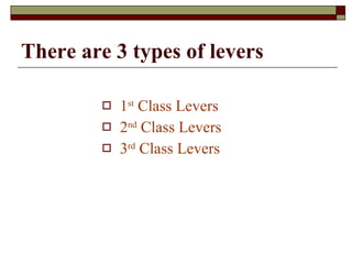
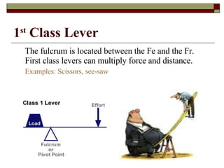
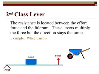
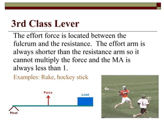
S: Types of Levers
Levers May 16, 2008
~ Archimedes Give me a place to stand and I will move the Earth.
Objectives Analyze and label the parts of a lever Provide examples of first, second and third class levers. Calculate and determine the mechanical advantage of a lever.
Forces in Machines   A  simple machine  is an unpowered mechanical device, such as a  lever .
Lever A bar that is free to move about a fixed point Parts of a lever Fulcrum  – The fixed point of a lever Effort Arm  – The part of the lever that the effort force is applied to (measured from the fulcrum to the point at which the force is applied) Resistance Arm  – The part of the lever that applies the resistance force (measured from the fulcrum to the center of the resistance force)
Anatomy of the lever Fulcrum  – point around which the lever rotates Input Force  – Force exerted  ON  the lever Output Force  – Force exerted  BY  the lever
Ideal Mechanical Advantage (IMA)  – What the mechanical advantage of a machine would be if there were no energy lost due to friction IMA  =  length of effort arm  =  l e   .  length of resistance arm  l r
By using the length of the effort arm and the resistance arm you can find the ideal mechanical advantage.  We can find the ideal mechanical advantage of any simple machine by dividing the effort distance by the resistance distance.
There are 3 types of levers 1 st  Class Levers 2 nd  Class Levers 3 rd  Class Levers
1 st  Class Lever The fulcrum is located between the Fe and the Fr.  First class levers can multiply force and distance. Examples: Scissors, see-saw
2 nd  Class Lever The resistance is located between the effort force and the fulcrum.  These levers multiply the force but the direction stays the same. Example:  Wheelbarrow
The effort force is located between the fulcrum and the resistance.  The effort arm is always shorter than the resistance arm so it cannot multiply the force and the MA is always less than 1. Examples: Rake, hockey stick 3rd Class Lever

Lever2008

  • 1.
  • 2.
  • 3.
    ~ Archimedes Giveme a place to stand and I will move the Earth.
  • 4.
    Objectives Analyze andlabel the parts of a lever Provide examples of first, second and third class levers. Calculate and determine the mechanical advantage of a lever.
  • 5.
    Forces in Machines A simple machine is an unpowered mechanical device, such as a lever .
  • 6.
    Lever A barthat is free to move about a fixed point Parts of a lever Fulcrum – The fixed point of a lever Effort Arm – The part of the lever that the effort force is applied to (measured from the fulcrum to the point at which the force is applied) Resistance Arm – The part of the lever that applies the resistance force (measured from the fulcrum to the center of the resistance force)
  • 7.
    Anatomy of thelever Fulcrum – point around which the lever rotates Input Force – Force exerted ON the lever Output Force – Force exerted BY the lever
  • 8.
    Ideal Mechanical Advantage(IMA) – What the mechanical advantage of a machine would be if there were no energy lost due to friction IMA = length of effort arm = l e . length of resistance arm l r
  • 9.
    By using thelength of the effort arm and the resistance arm you can find the ideal mechanical advantage. We can find the ideal mechanical advantage of any simple machine by dividing the effort distance by the resistance distance.
  • 10.
    There are 3types of levers 1 st Class Levers 2 nd Class Levers 3 rd Class Levers
  • 11.
    1 st Class Lever The fulcrum is located between the Fe and the Fr. First class levers can multiply force and distance. Examples: Scissors, see-saw
  • 12.
    2 nd Class Lever The resistance is located between the effort force and the fulcrum. These levers multiply the force but the direction stays the same. Example: Wheelbarrow
  • 13.
    The effort forceis located between the fulcrum and the resistance. The effort arm is always shorter than the resistance arm so it cannot multiply the force and the MA is always less than 1. Examples: Rake, hockey stick 3rd Class Lever