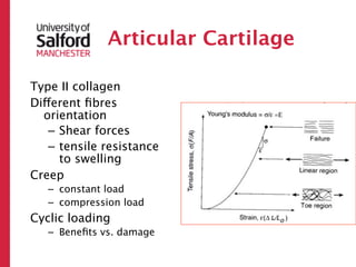
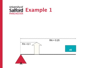
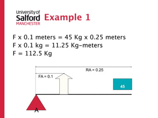
Torque = Force x Force Arm
= Resistance x Resistance Arm
= 45 kg x 0.25 m
= 11.25 Nm
So the force needed is 11.25 N
Therefore, the torque needed is 1.125 Nm (11.25 N x 0.1 m)
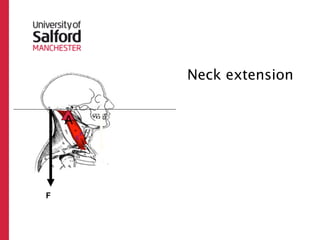
Joint Mobility and
Mobilitysometimes has very distinct
endpoints
– Elbow or knee hyperextension
In other cases variable soft tissue
properties and other factors limit ROM
Some see stability as the joint’s ability to
resist dislocation.
Stability
10.
Joint Mobility and
Mobilitysometimes has very distinct
endpoints
– Elbow or knee hyperextension
In other cases variable soft tissue
properties and other factors limit ROM
Some see stability as the joint’s ability to
resist dislocation.
Stability
hi p!
pt the
e
Exc
11.
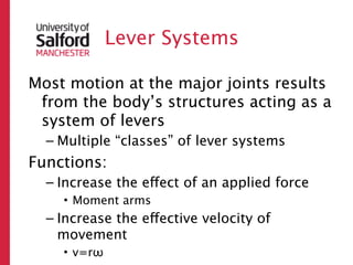
Lever Systems
Most motionat the major joints results
from the body’s structures acting as a
system of levers
– Multiple “classes” of lever systems
Functions:
– Increase the effect of an applied force
• Moment arms
– Increase the effective velocity of
movement
• v=rω
Levers
• Levers areused to alter the resulting
direction of the applied force
14.
Levers
• Levers areused to alter the resulting
direction of the applied force
• A lever is a rigid bar (bone) that turns
about an axis of rotation or fulcrum (joint)
15.
Levers
• Levers areused to alter the resulting
direction of the applied force
• A lever is a rigid bar (bone) that turns
about an axis of rotation or fulcrum (joint)
• The lever rotates about the axis as a result
of a force (from muscle contraction)
16.
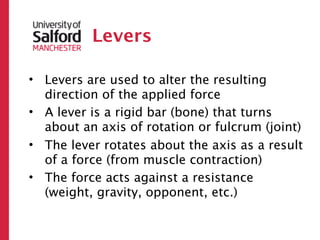
Levers
• Levers areused to alter the resulting
direction of the applied force
• A lever is a rigid bar (bone) that turns
about an axis of rotation or fulcrum (joint)
• The lever rotates about the axis as a result
of a force (from muscle contraction)
• The force acts against a resistance
(weight, gravity, opponent, etc.)
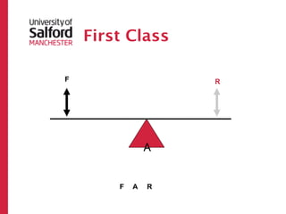
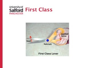
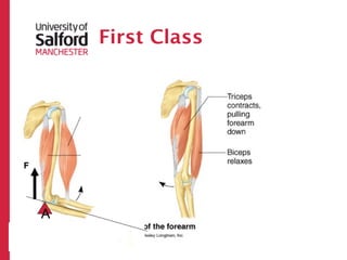
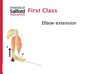
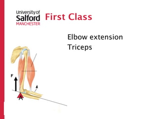
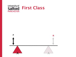
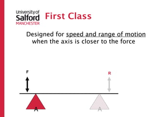
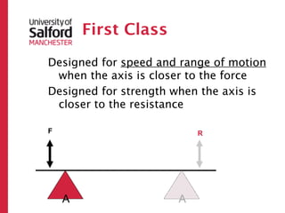
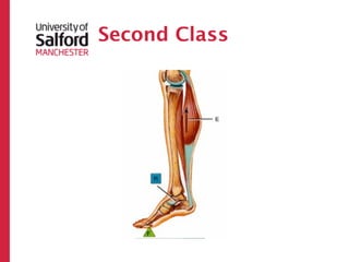
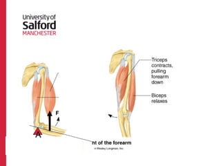
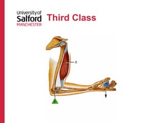
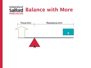
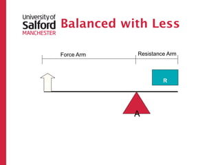
First Class
Designed forspeed and range of motion
when the axis is closer to the force
Designed for strength when the axis is
closer to the resistance
F R
A A
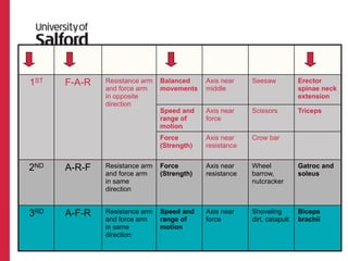
FUNCTIONAL RELATIONSHIP PRACTICAL HUMAN
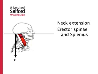
CLASS ARRANGEMENT ARM MOVEMENT DESIGN TO AXIS EXAMPLE EXAMPLE
1ST F-A-R Resistance arm Balanced Axis near Seesaw Erector
and force arm movements middle spinae neck
in opposite extension
direction
Speed and Axis near Scissors Triceps
range of force
motion
Force Axis near Crow bar
(Strength) resistance
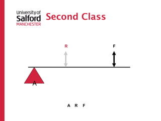
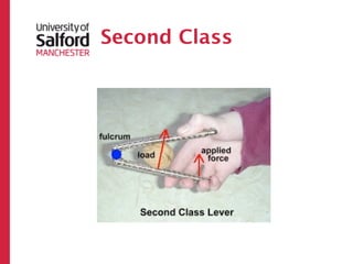
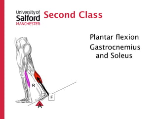
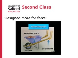
2ND A-R-F Resistance arm Force Axis near Wheel Gatroc and
and force arm (Strength) resistance barrow, soleus
in same nutcracker
direction
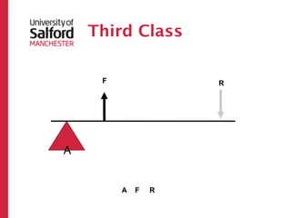
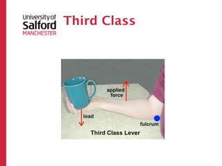
3RD A-F-R Resistance arm Speed and Axis near Shoveling Biceps
and force arm range of force dirt, catapult brachii
in same motion
direction
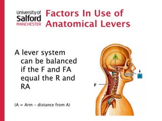
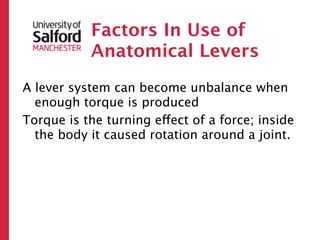
Factors In Useof
Anatomical Levers
A lever system can become unbalance when
enough torque is produced
55.
Factors In Useof
Anatomical Levers
A lever system can become unbalance when
enough torque is produced
Torque is the turning effect of a force; inside
the body it caused rotation around a joint.
56.
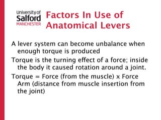
Factors In Useof
Anatomical Levers
A lever system can become unbalance when
enough torque is produced
Torque is the turning effect of a force; inside
the body it caused rotation around a joint.
Torque = Force (from the muscle) x Force
Arm (distance from muscle insertion from
the joint)
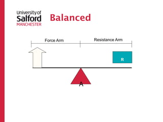
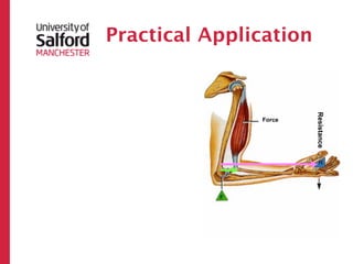
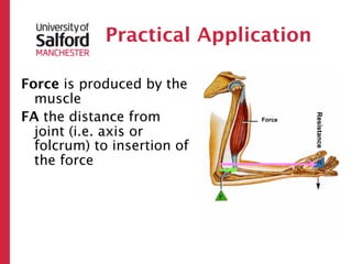
Practical Application
Force isproduced by the
muscle
FA the distance from
Resistance
Force
joint (i.e. axis or
folcrum) to insertion of
the force
60.
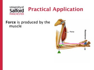
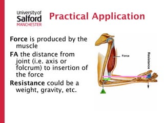
Practical Application
Force isproduced by the
muscle
FA the distance from
Resistance
Force
joint (i.e. axis or
folcrum) to insertion of
the force
Resistance could be a
weight, gravity, etc.
61.
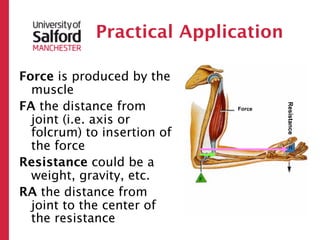
Practical Application
Force isproduced by the
muscle
FA the distance from
Resistance
Force
joint (i.e. axis or
folcrum) to insertion of
the force
Resistance could be a
weight, gravity, etc.
RA the distance from
joint to the center of
the resistance
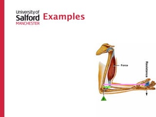
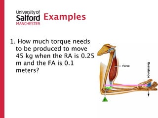
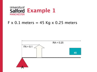
Examples
1. How muchtorque needs
to be produced to move
45 kg when the RA is 0.25
m and the FA is 0.1
Resistance
Force
meters?
64.
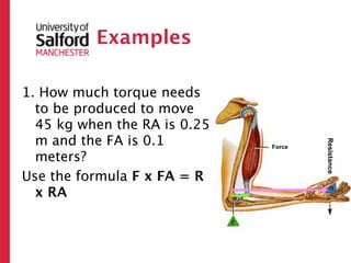
Examples
1. How muchtorque needs
to be produced to move
45 kg when the RA is 0.25
m and the FA is 0.1
Resistance
Force
meters?
Use the formula F x FA = R
x RA
65.
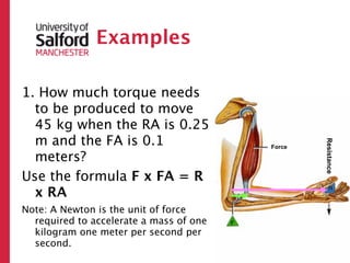
Examples
1. How muchtorque needs
to be produced to move
45 kg when the RA is 0.25
m and the FA is 0.1
Resistance
Force
meters?
Use the formula F x FA = R
x RA
Note: A Newton is the unit of force
required to accelerate a mass of one
kilogram one meter per second per
second.
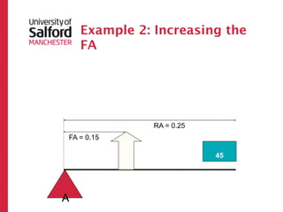
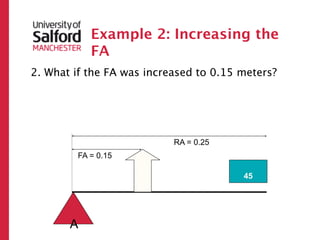
Example 2: Increasingthe
FA
2. What if the FA was increased to 0.15 meters?
RA = 0.25
FA = 0.15
?
45
A
72.
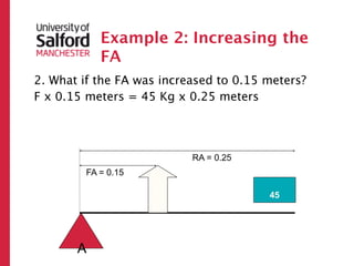
Example 2: Increasingthe
FA
2. What if the FA was increased to 0.15 meters?
F x 0.15 meters = 45 Kg x 0.25 meters
RA = 0.25
FA = 0.15
?
45
A
73.
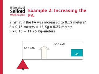
Example 2: Increasingthe
FA
2. What if the FA was increased to 0.15 meters?
F x 0.15 meters = 45 Kg x 0.25 meters
F x 0.15 = 11.25 Kg-meters
RA = 0.25
FA = 0.15
?
45
A
74.
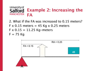
Example 2: Increasingthe
FA
2. What if the FA was increased to 0.15 meters?
F x 0.15 meters = 45 Kg x 0.25 meters
F x 0.15 = 11.25 Kg-meters
F = 75 Kg
RA = 0.25
FA = 0.15
?
45
A
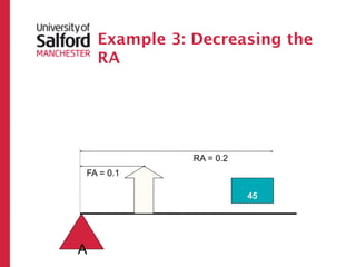
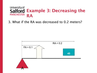
Example 3: Decreasingthe
RA
3. What if the RA was decreased to 0.2 meters?
RA = 0.2
FA = 0.1
?
45
A
77.
Example 3: Decreasingthe
RA
3. What if the RA was decreased to 0.2 meters?
F x 0.1 meters = 45 Kg x 0.2 meters
RA = 0.2
FA = 0.1
?
45
A
78.
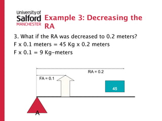
Example 3: Decreasingthe
RA
3. What if the RA was decreased to 0.2 meters?
F x 0.1 meters = 45 Kg x 0.2 meters
F x 0.1 = 9 Kg-meters
RA = 0.2
FA = 0.1
?
45
A
79.
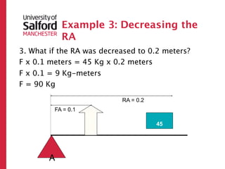
Example 3: Decreasingthe
RA
3. What if the RA was decreased to 0.2 meters?
F x 0.1 meters = 45 Kg x 0.2 meters
F x 0.1 = 9 Kg-meters
F = 90 Kg
RA = 0.2
FA = 0.1
?
45
A
Summary
• The actualtorque needed to move a
given resistance depends on the
length of the FA and RA
82.
Summary
• The actualtorque needed to move a
given resistance depends on the
length of the FA and RA
• As the FA increases or RA
decreases, the required torque
decreases.
83.
Summary
• The actualtorque needed to move a
given resistance depends on the
length of the FA and RA
• As the FA increases or RA
decreases, the required torque
decreases.
• As the FA decreases or RA
increases, the required torque
Levers Continued
Inside thebody, several joints can be
“added” together to increase
leverage (e.g. shoulder, elbow, and
wrist.
86.
Levers Continued
Inside thebody, several joints can be
“added” together to increase
leverage (e.g. shoulder, elbow, and
wrist.
An increase in leverage can increase
velocity
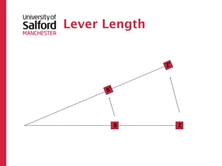
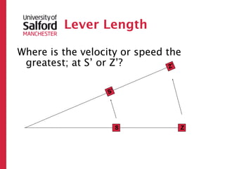
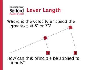
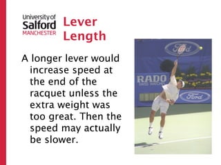
Lever
Length
A longer lever would
increase speed at
the end of the
racquet unless the
extra weight was
too great. Then the
speed may actually
be slower.
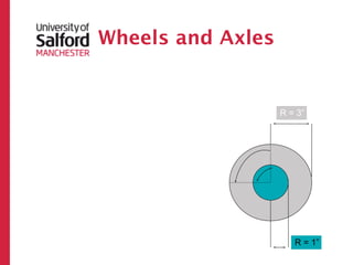
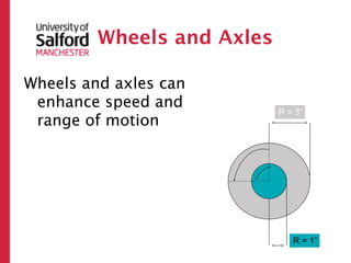
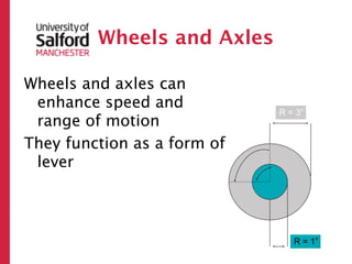
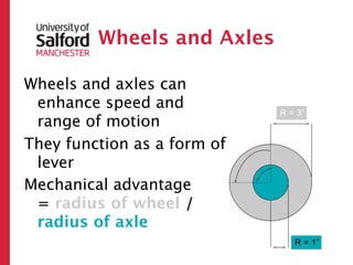
Wheels and Axles
Wheelsand axles can
enhance speed and
R = 3”
range of motion
They function as a form of
lever
R = 1”
100.
Wheels and Axles
Wheelsand axles can
enhance speed and
R = 3”
range of motion
They function as a form of
lever
Mechanical advantage
= radius of wheel /
radius of axle
R = 1”
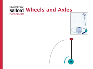
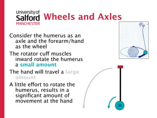
Wheels and Axles
Considerthe humerus as an
axle and the forearm/hand
as the wheel
The rotator cuff muscles
inward rotate the humerus
a small amount
H
104.
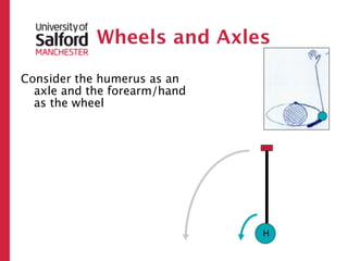
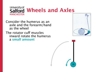
Wheels and Axles
Considerthe humerus as an
axle and the forearm/hand
as the wheel
The rotator cuff muscles
inward rotate the humerus
a small amount
The hand will travel a large
amount
H
105.
Wheels and Axles
Considerthe humerus as an
axle and the forearm/hand
as the wheel
The rotator cuff muscles
inward rotate the humerus
a small amount
The hand will travel a large
amount
A little effort to rotate the
humerus, results in a
significant amount of
movement at the hand
H
106.
Joints and
moments
Note, as a joint moves through its
ROM, two things change:
– Instantaneous Center of Rotation
• Rotation
• Sliding
• Rolling
– Muscle Line of Action
These combine to change the moment
arm
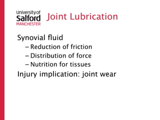
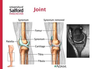
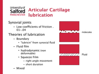
#8 Synovial joint lubrication: in spite of the massive loads generated in them, synovial joints are efficient bearings with very low friction. The coefficient of friction of a synovial joint is around 0.02. This compares to 0.03 for ice sliding on ice. A coefficient of friction of 0.01 means that a load of 100 lb could be made to slide by applying a force of 1lb. Joint lubrication is the key to reduced friction. So, it is helpful to understand them in order to better understand and treat joint wear. It is still unclear how lubrication works, but there are many theories, based on man-made ball-bearings. What is clear is that no single mechanism is responsible and different modes of lubrication work at different stages of joint function. The joint is lined by wear resistant hyaline cartilage and is bathed by synovial fluid. Unlike a typical newtonian fluid synovial fluid has a viscosity that decreases with increasing shear rate. The function of a lubricant is to provide an intermediate layer with low shear resistance in between the two sliding surfaces to reduce friction. A thixotropic fluid would fit the bill perfectly.\nBasic lubrication is of two types: fluid-film, boundary and mixed.\nFluid film : a thin fluid film separates the bearing surfaces. Of two types: hydrodynamic and squeeze film. Hydrodynamic lubrication is unlikely to be feasible in vivo as the sliding velocity of joints are too low to generate a substantial fluid film. Squeeze film lubrication takes place by the production of a fluid film under pressure as the two bearing surfaces move perpendicularly towards each other. Fluid film and resultant load bearing capacity depends on fluid viscosity. It could explain lubrication under sudden loading but is not suitable for prolong loading conditions.\nBoundary: the bearing surfaces come to contact with each other, but "lubricin" from synovial fluid is attached to the cartilage surface and offers an interposed layer which when rubbed provides less resistance to shear.\nMixed: weeping lubrication: on load application synovial fluid is released or "wept" from articular cartilage. It separates the two bearing surfaces and reduces friction due to the hydrostatic pressure. On unloading the fluid is squeezed back in. This mechanism is not dependent on sliding speed .\n