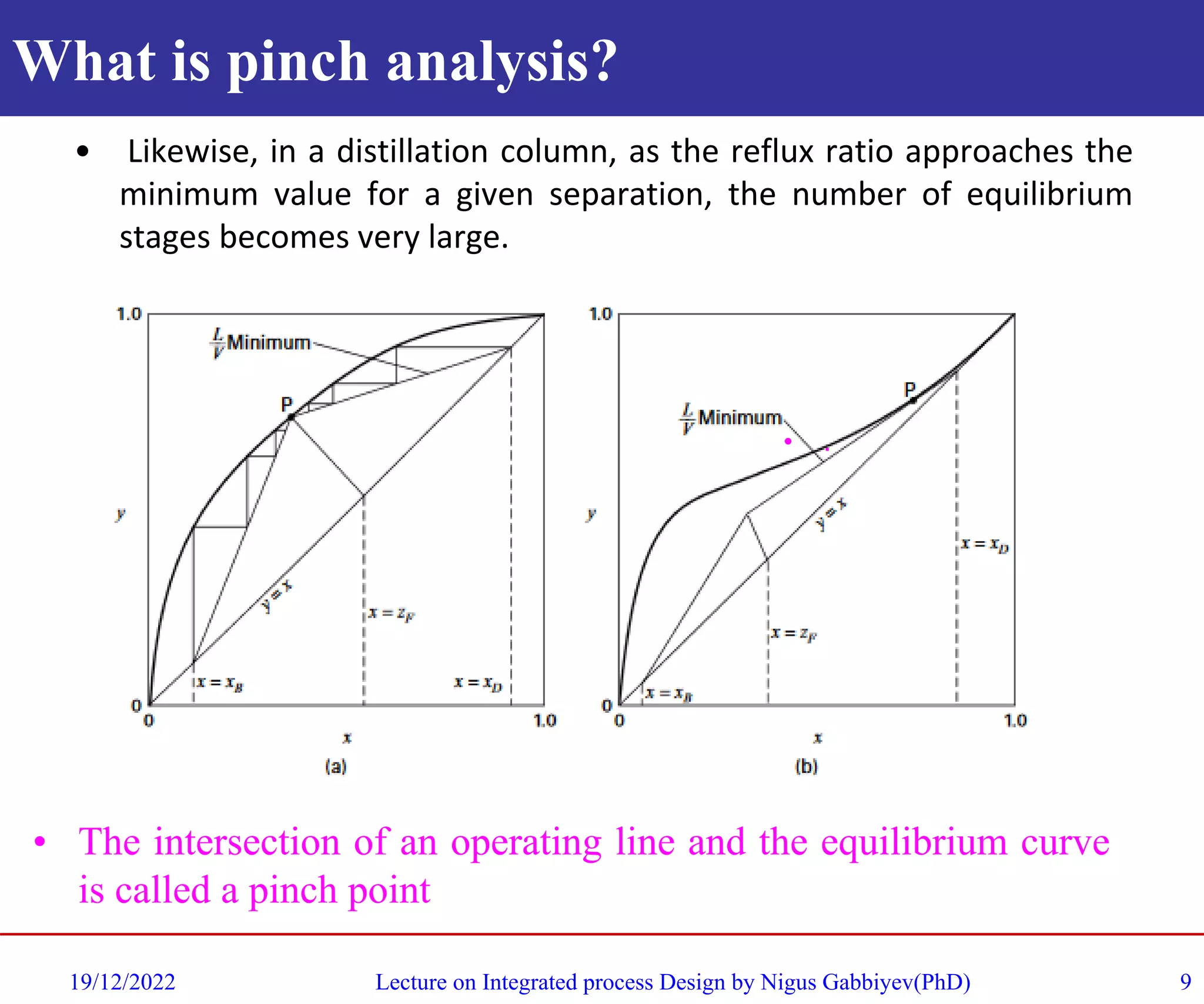
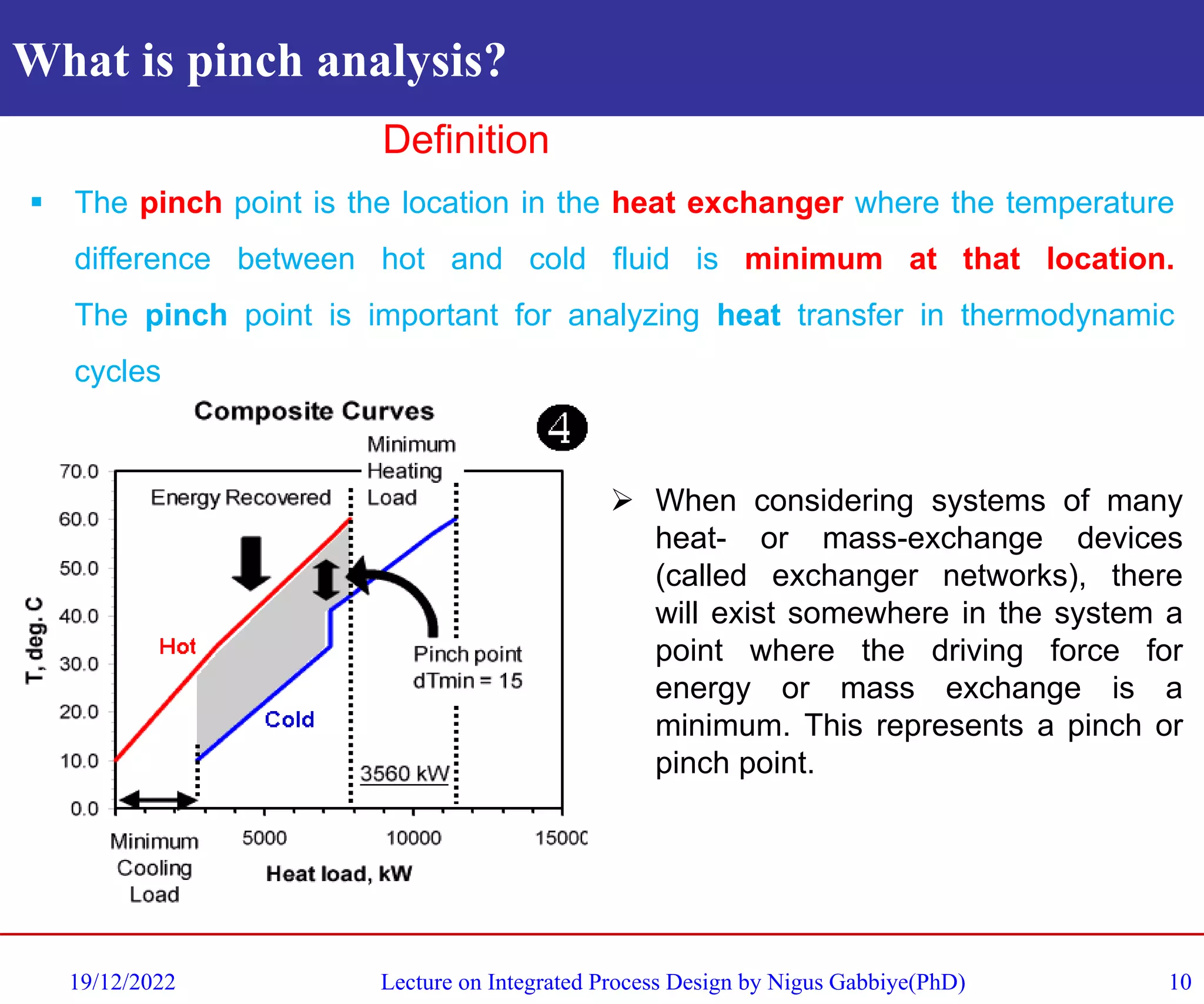
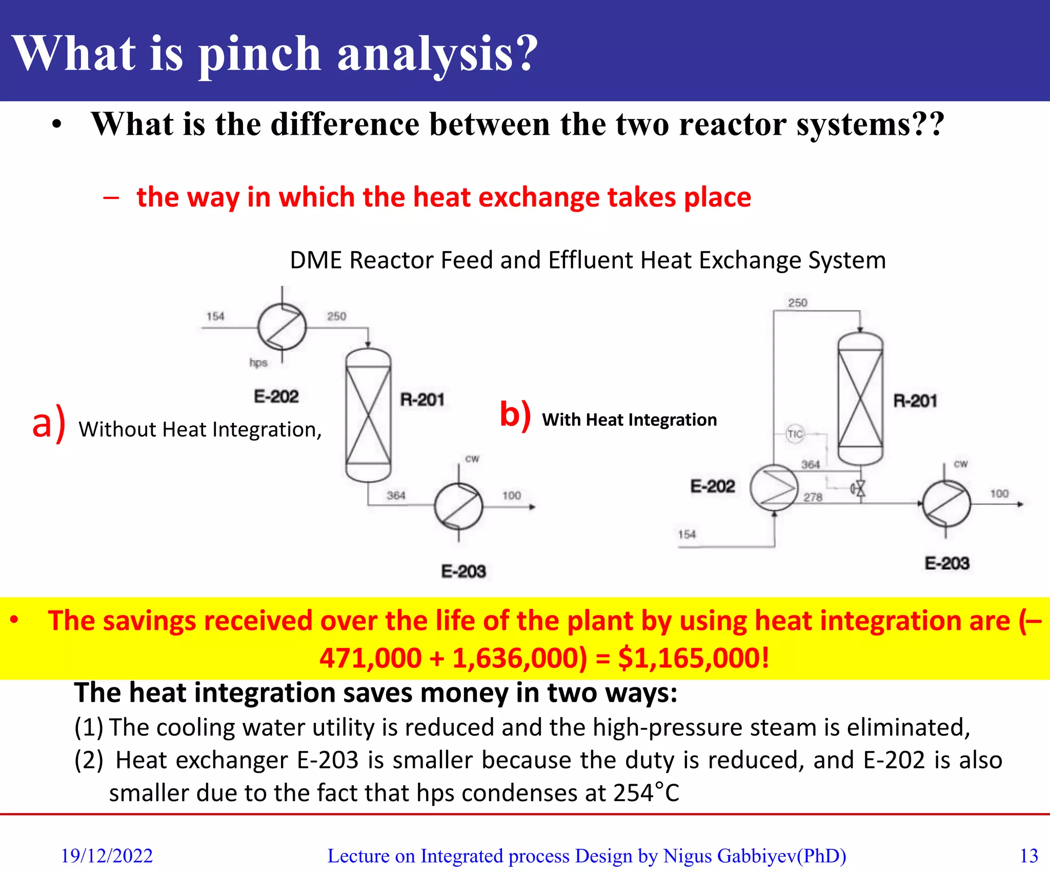
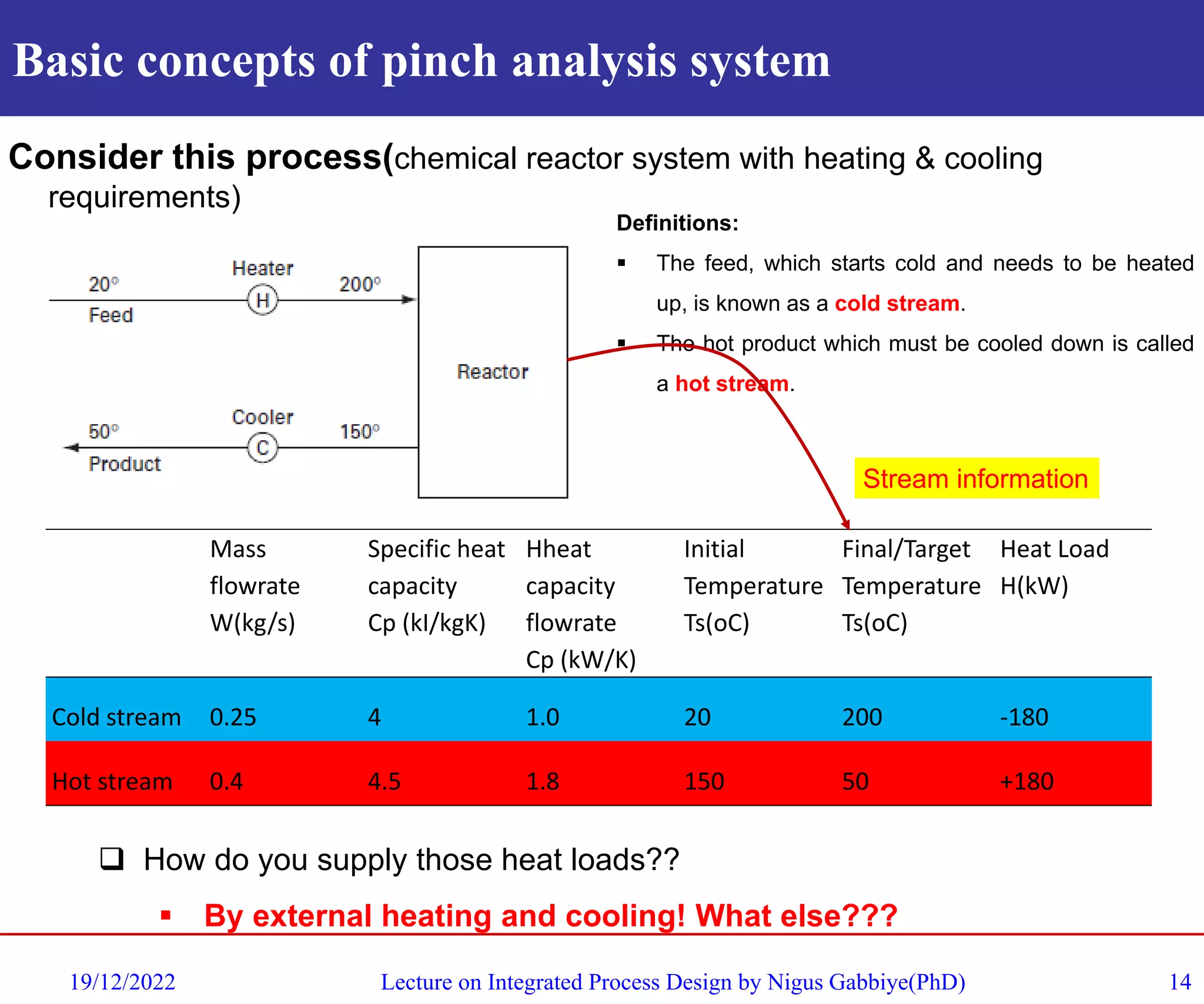
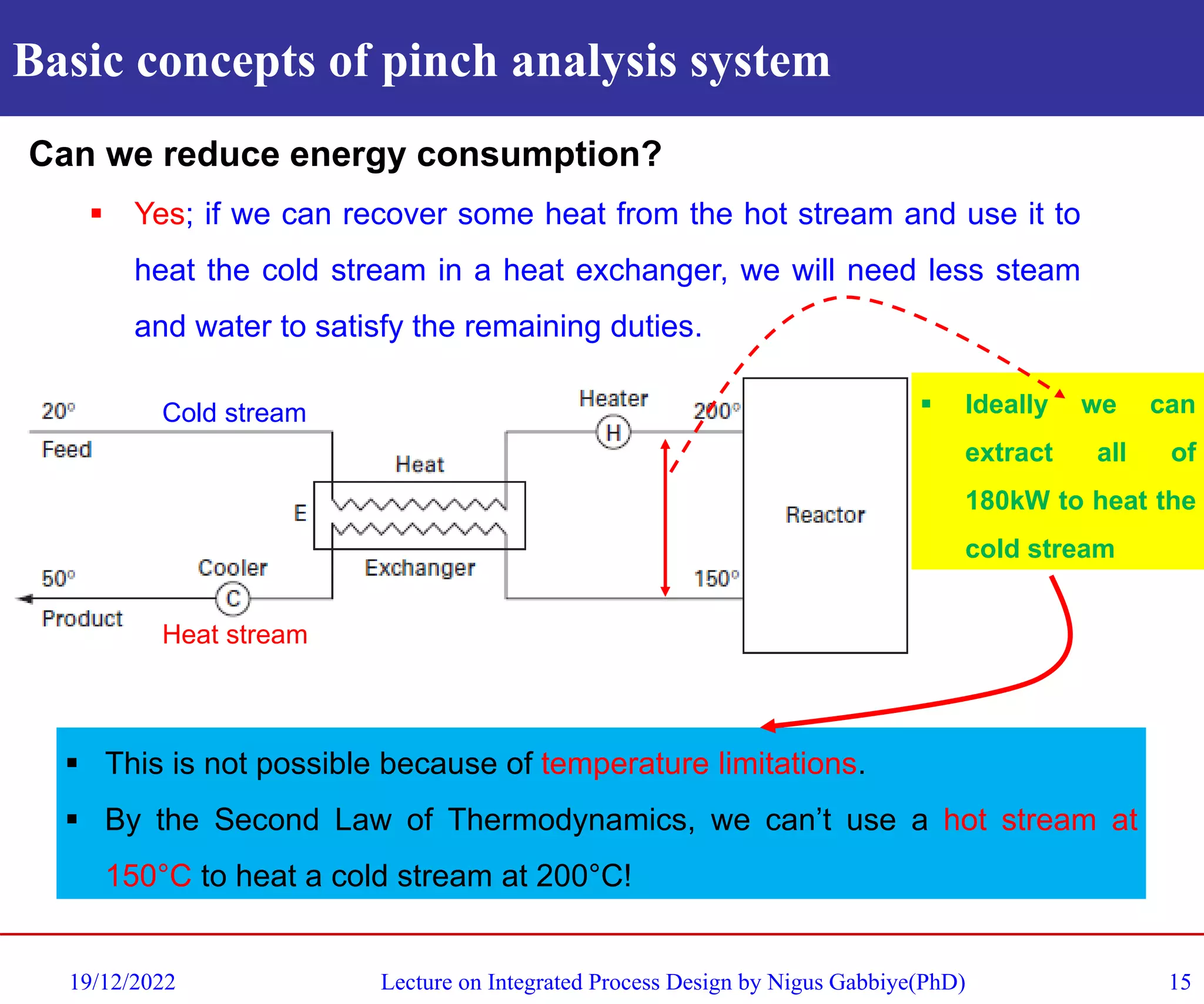
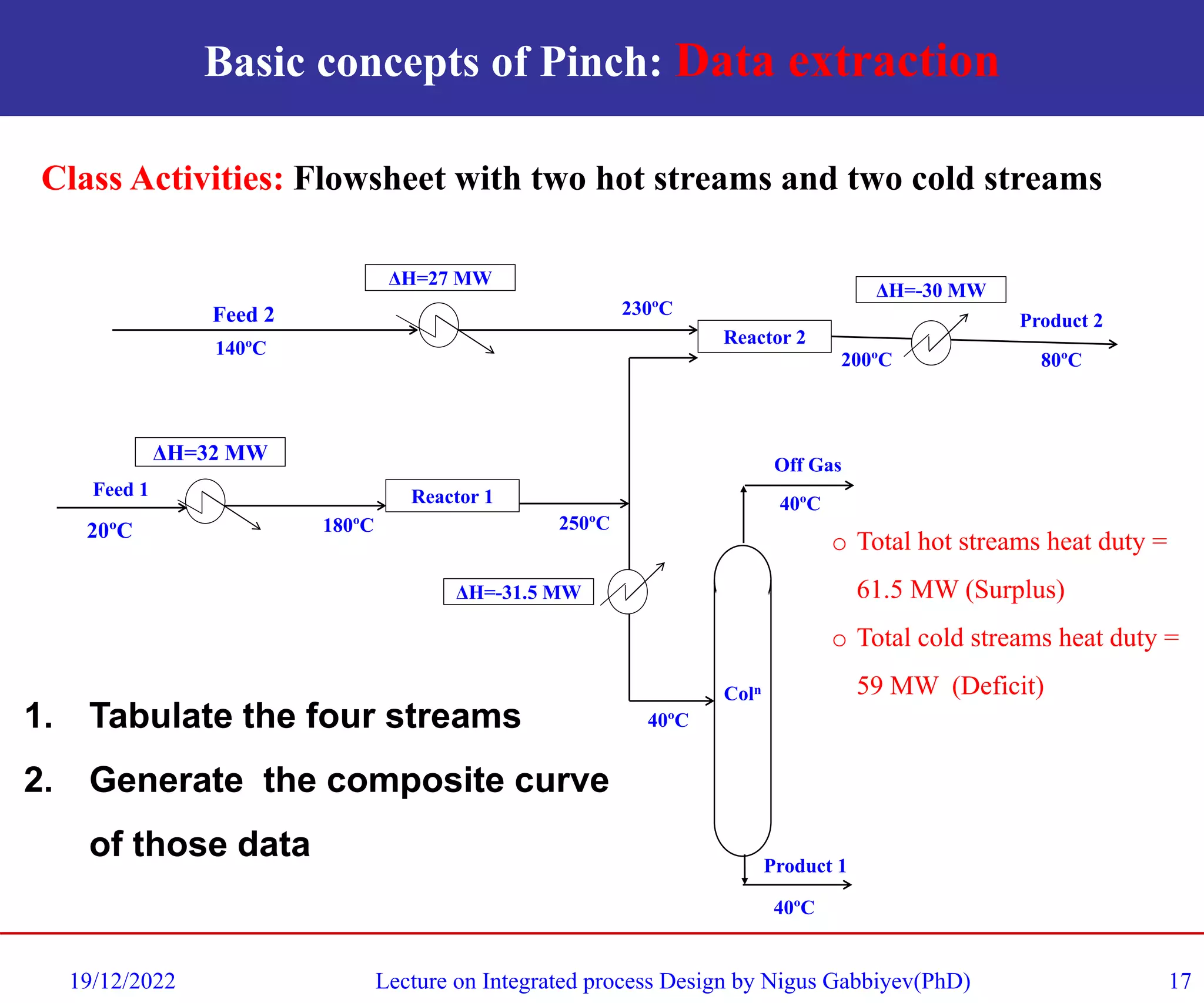
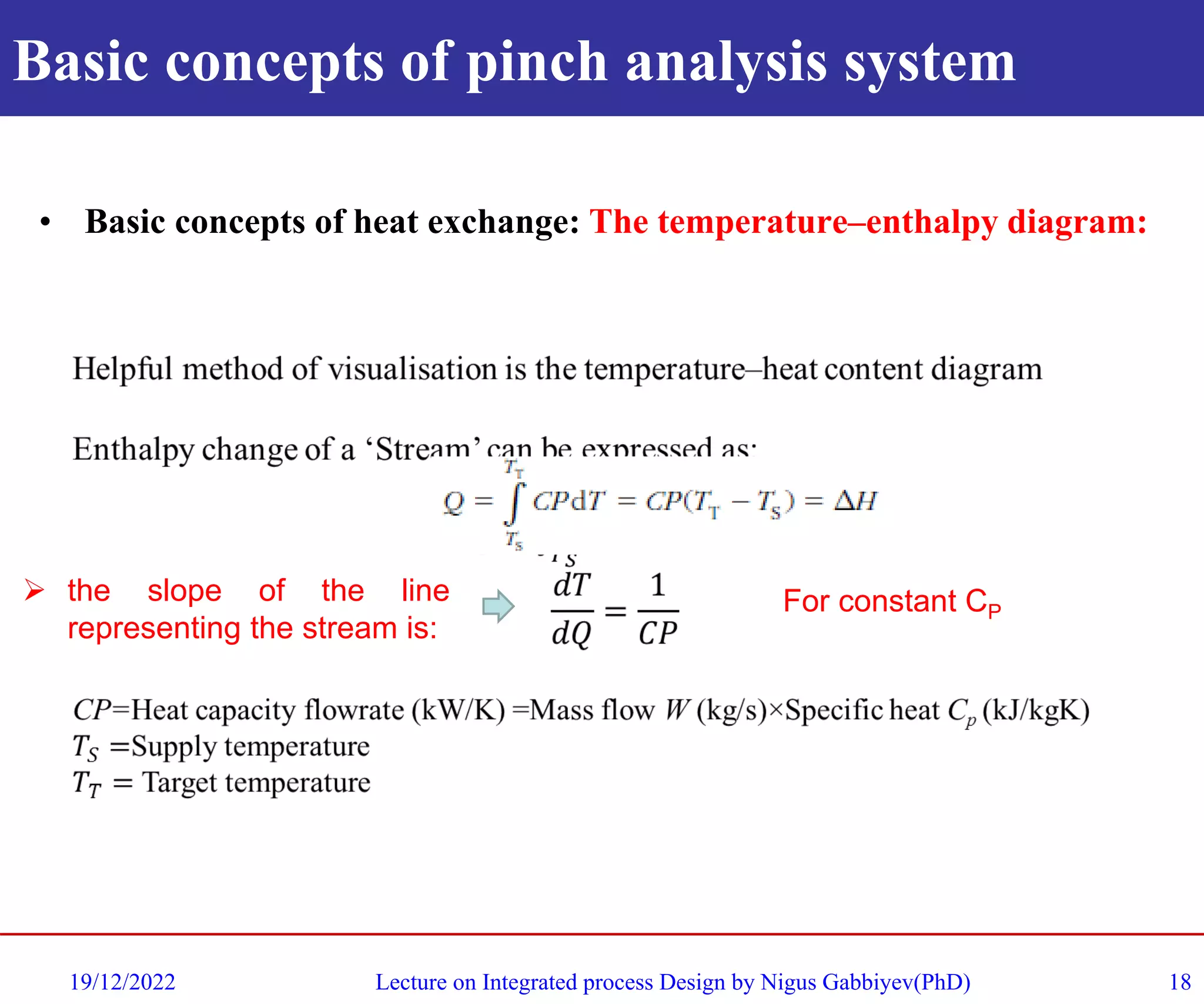
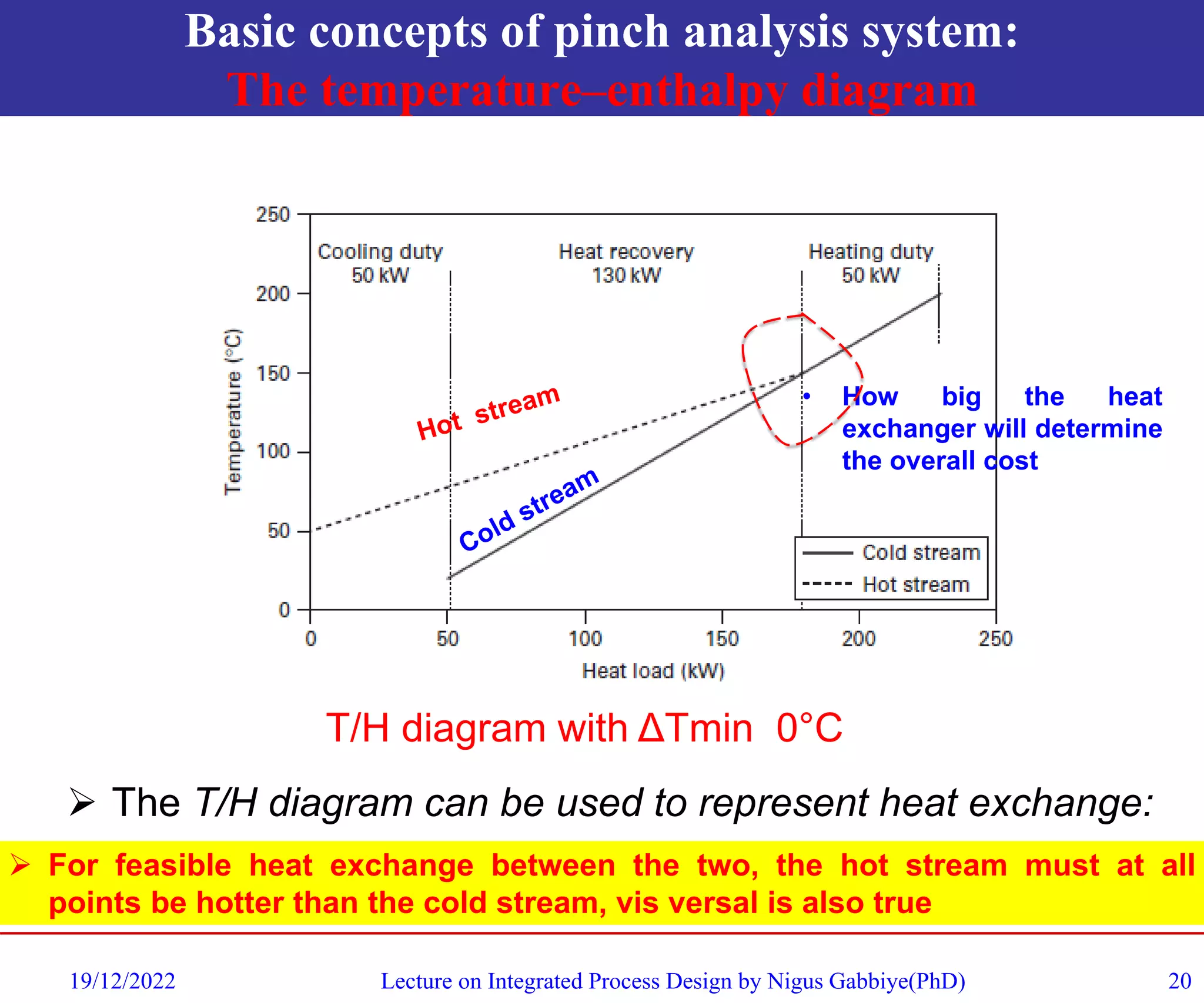
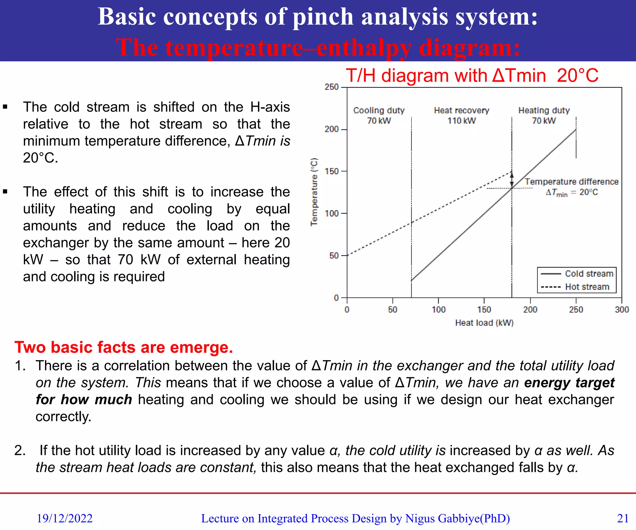
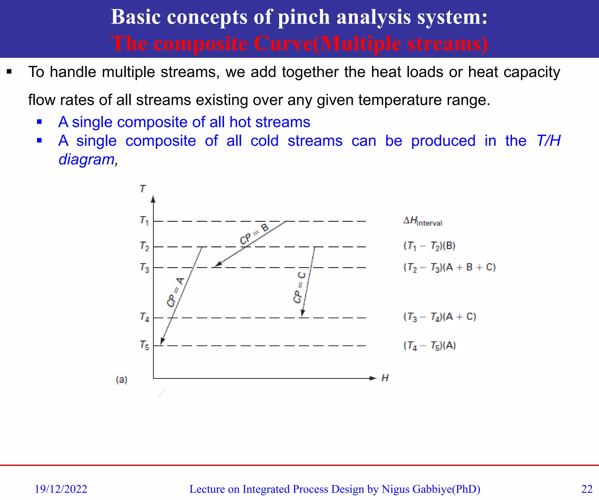
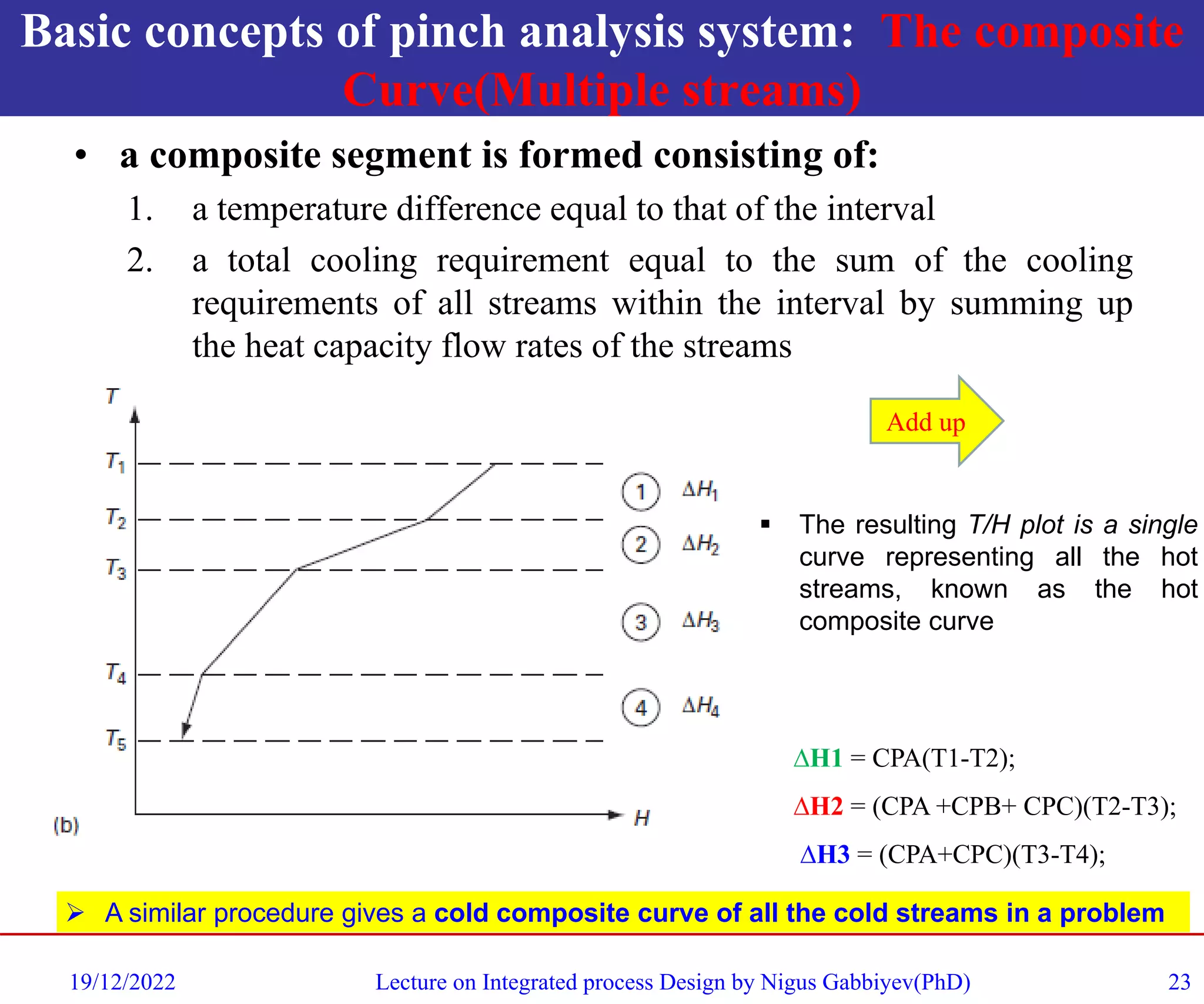
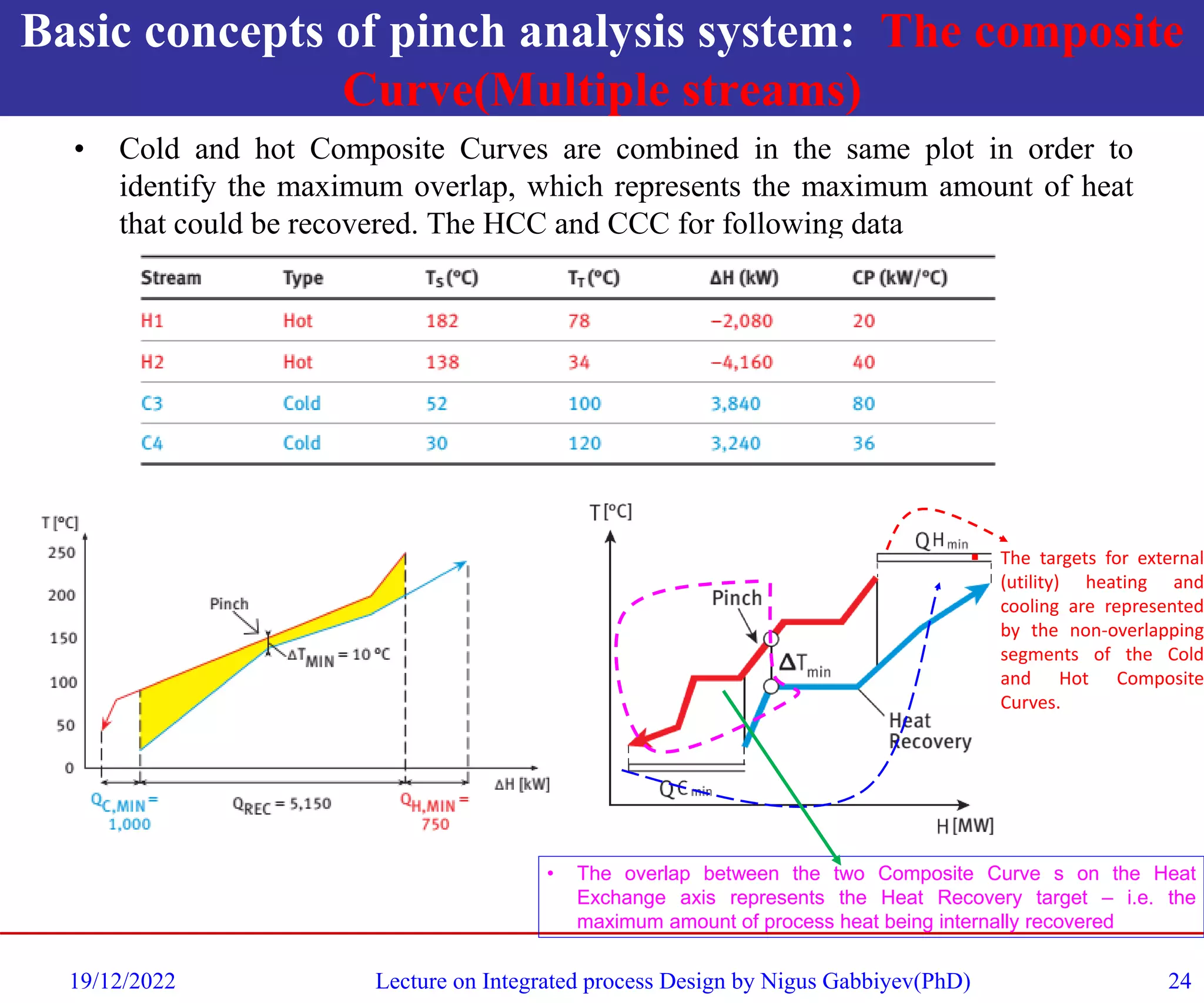
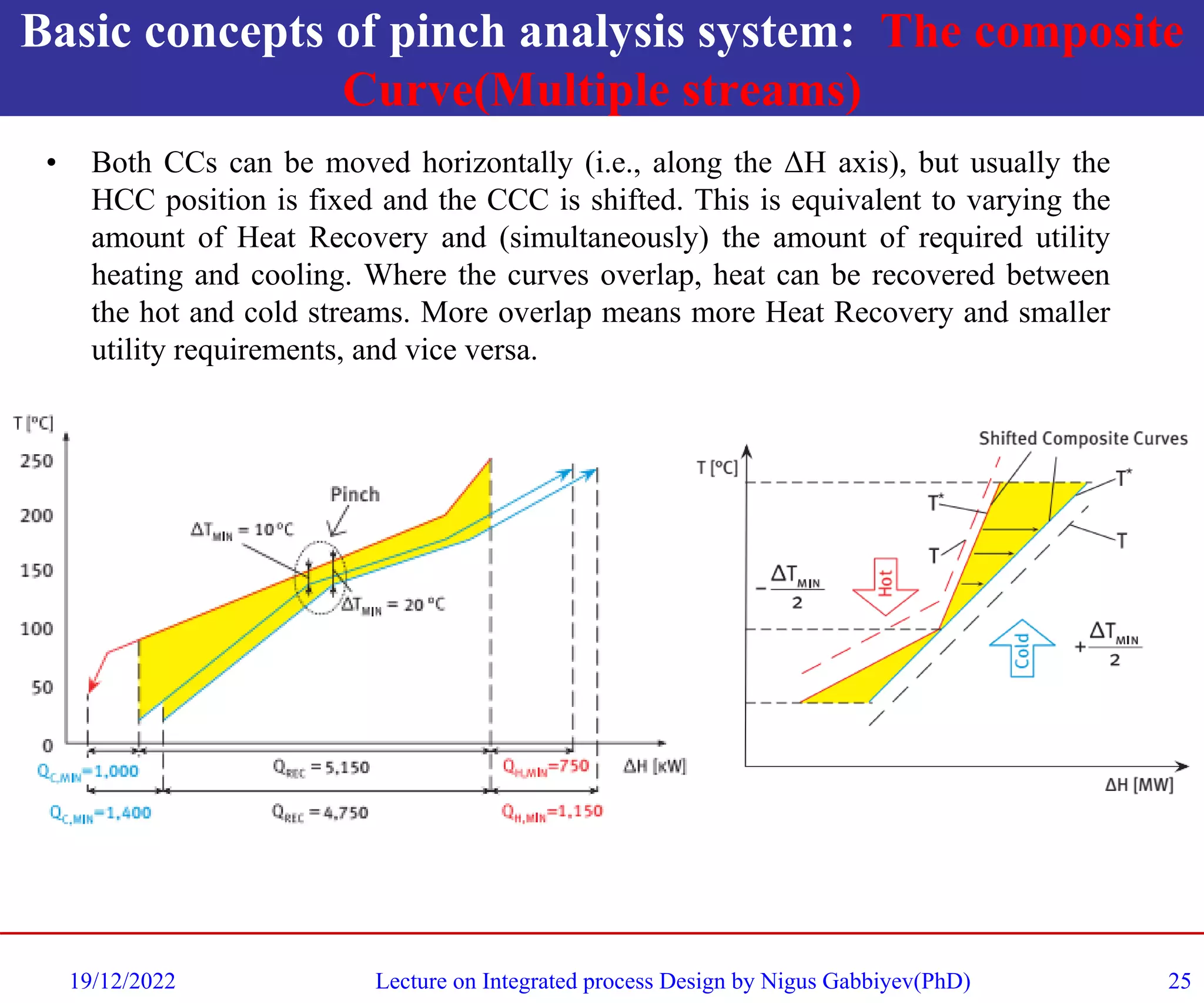
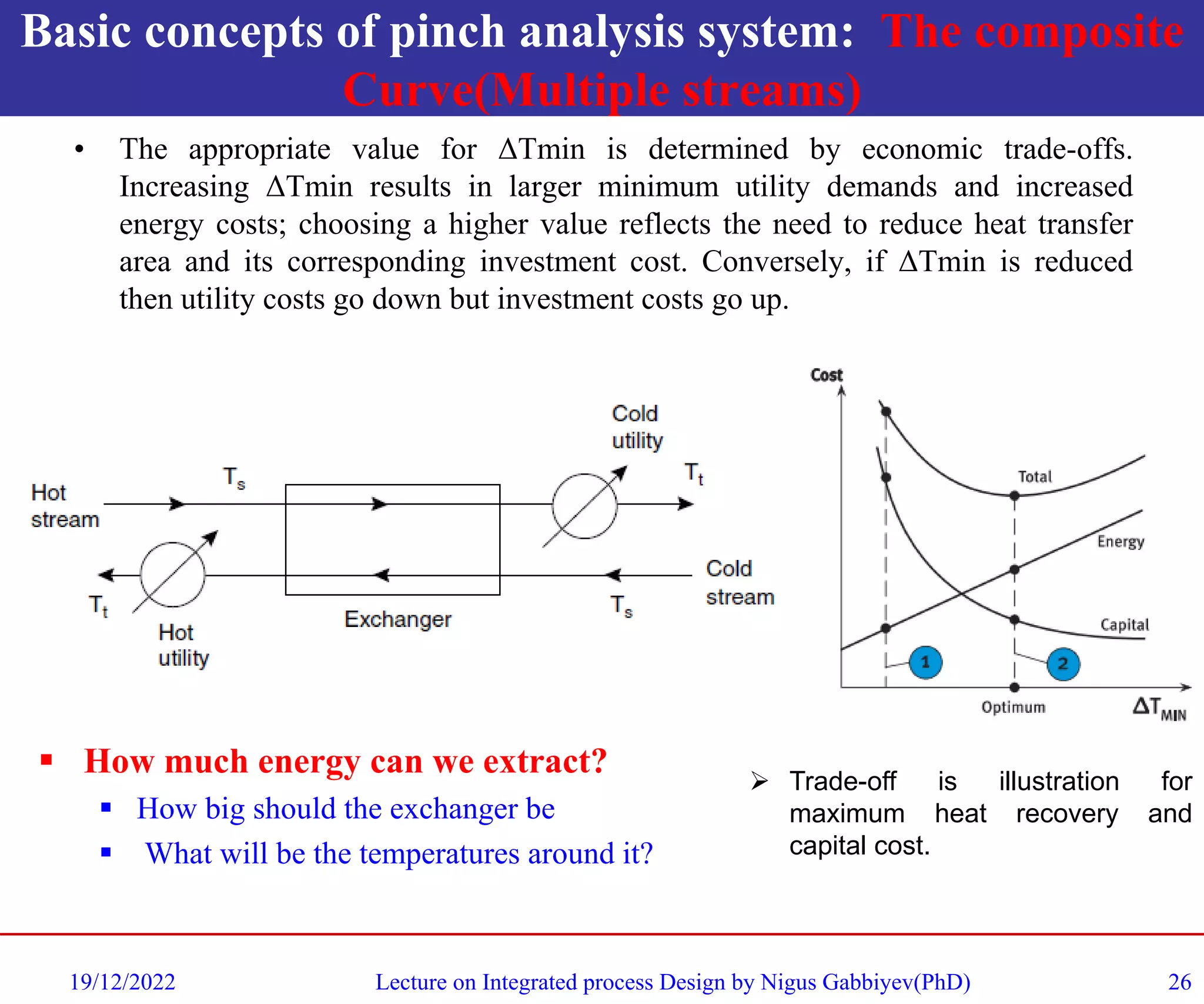
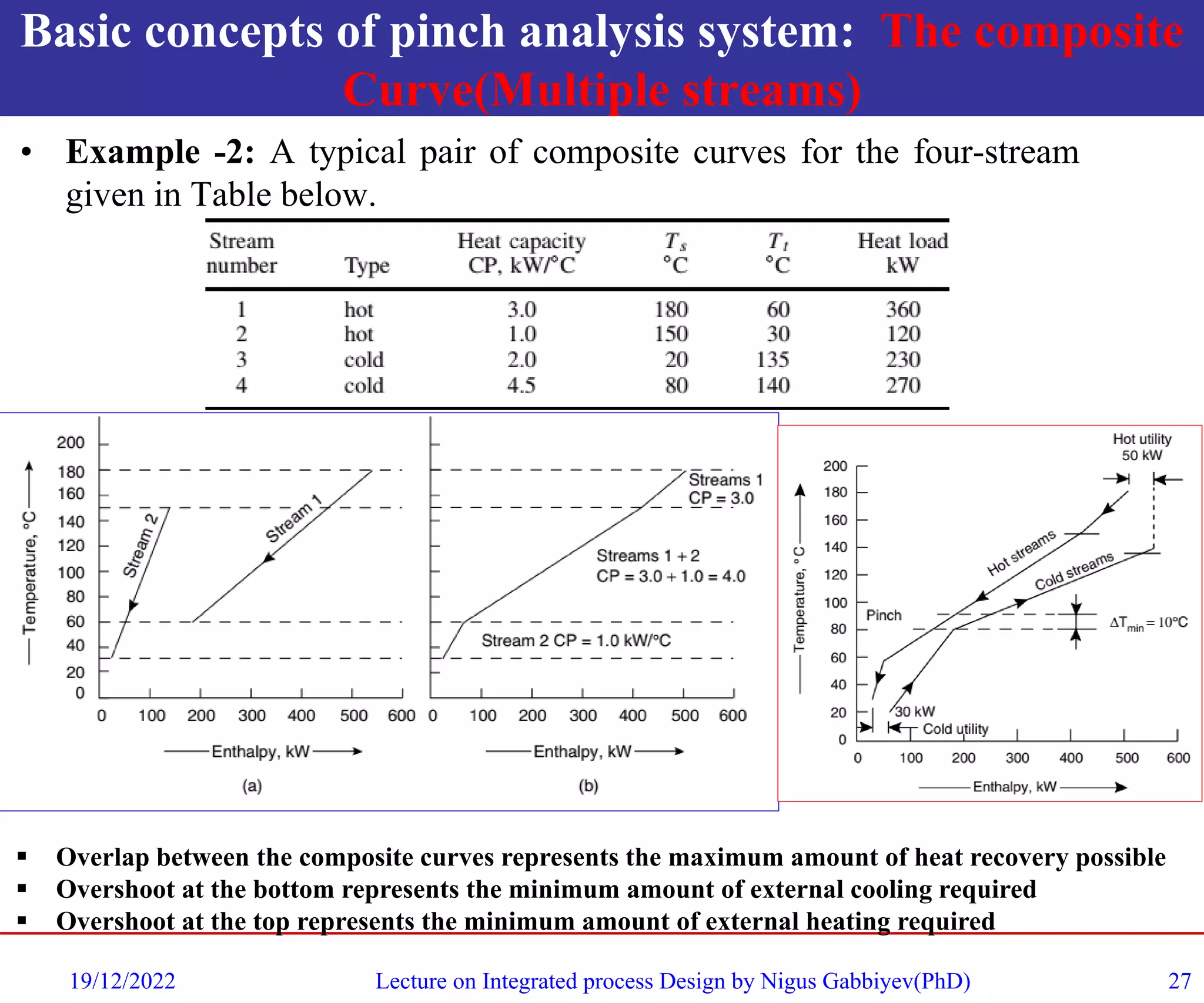
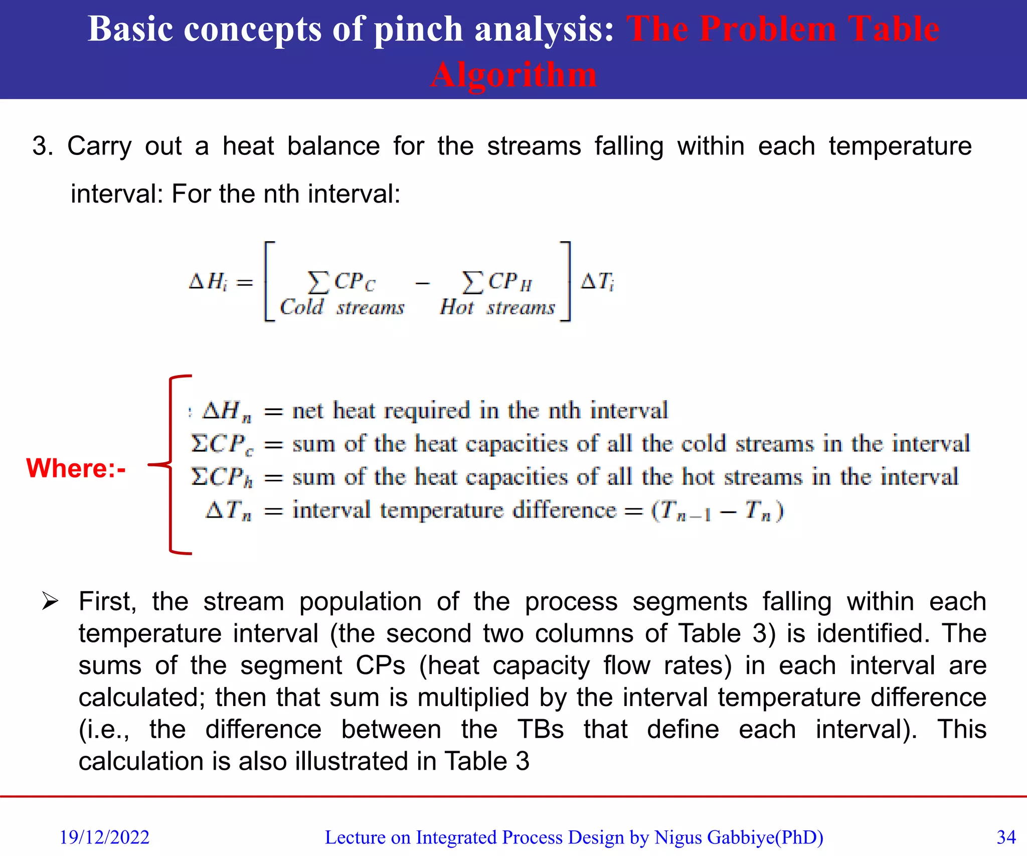
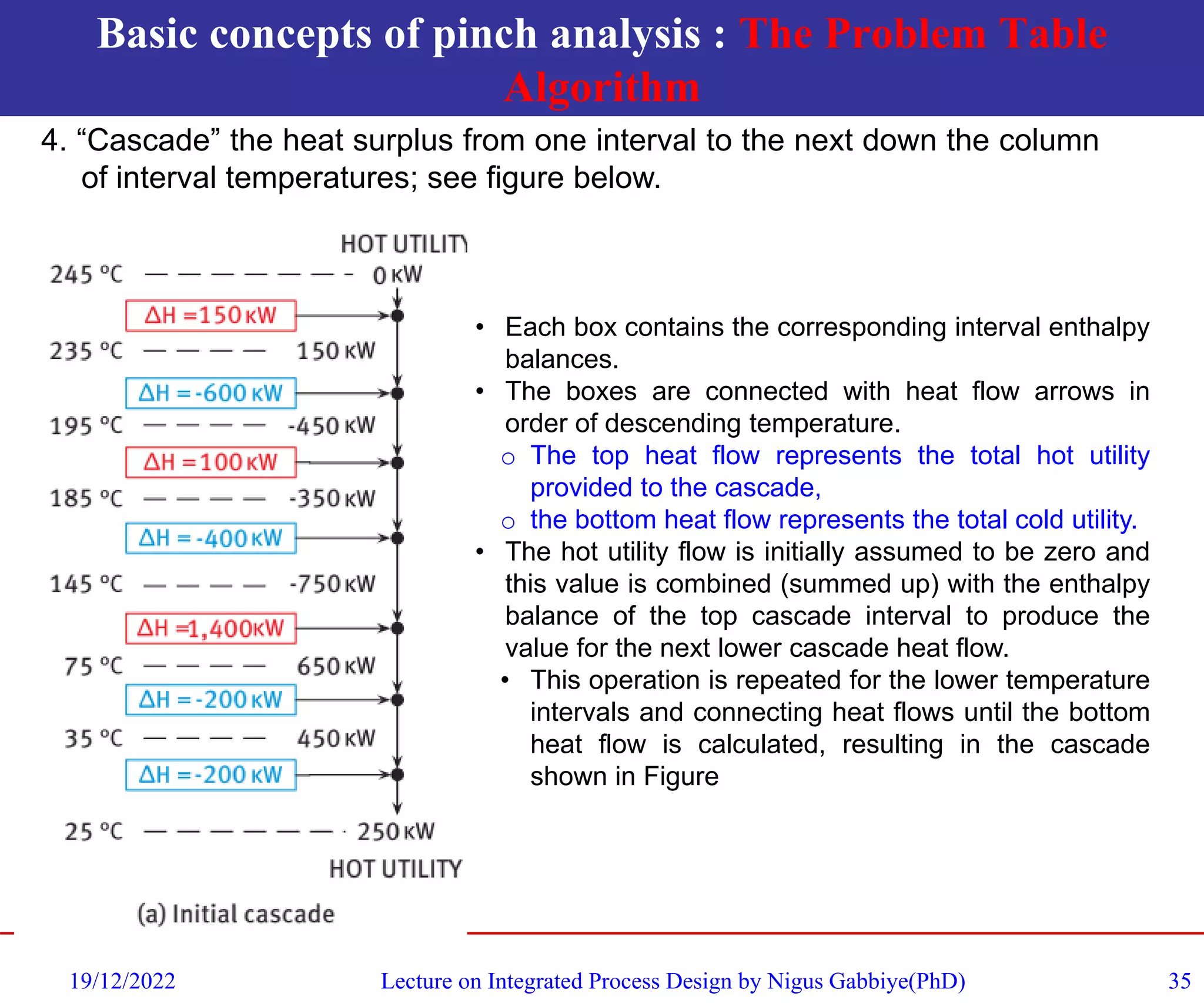
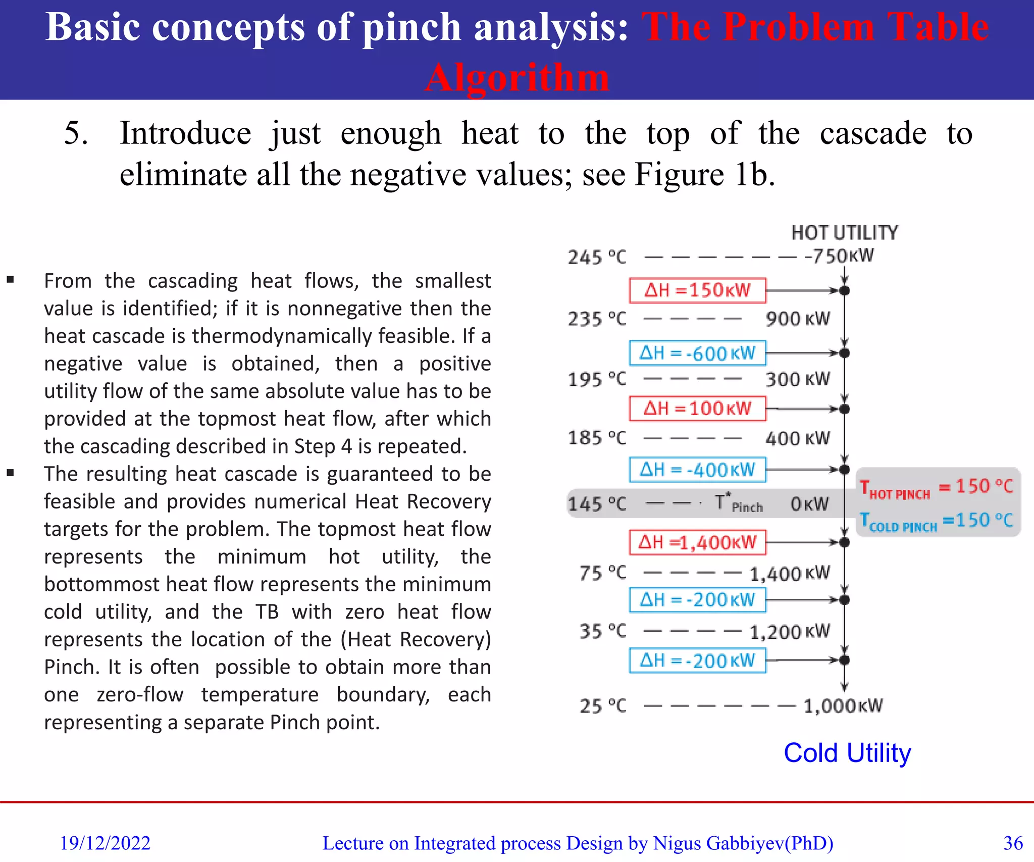
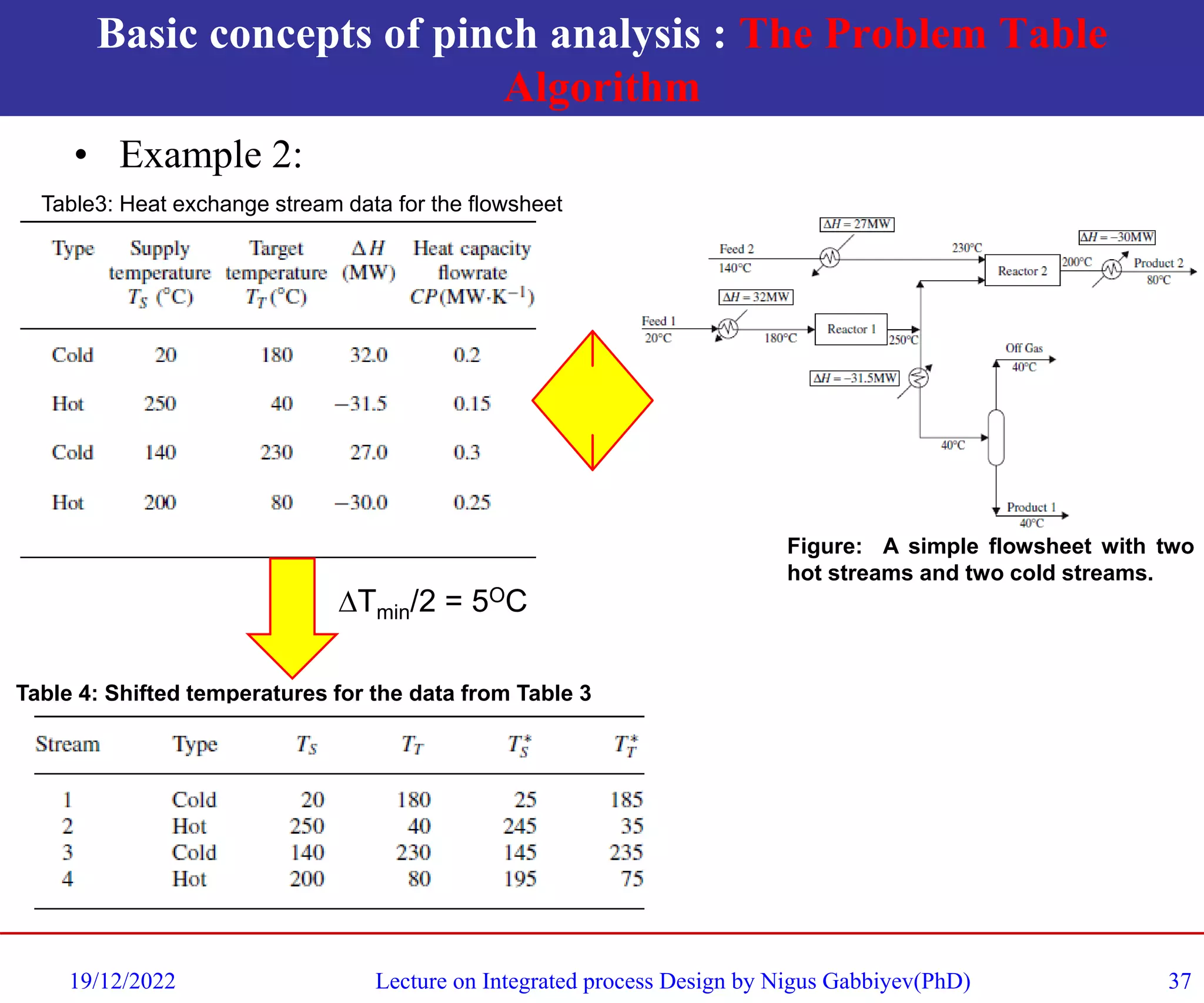
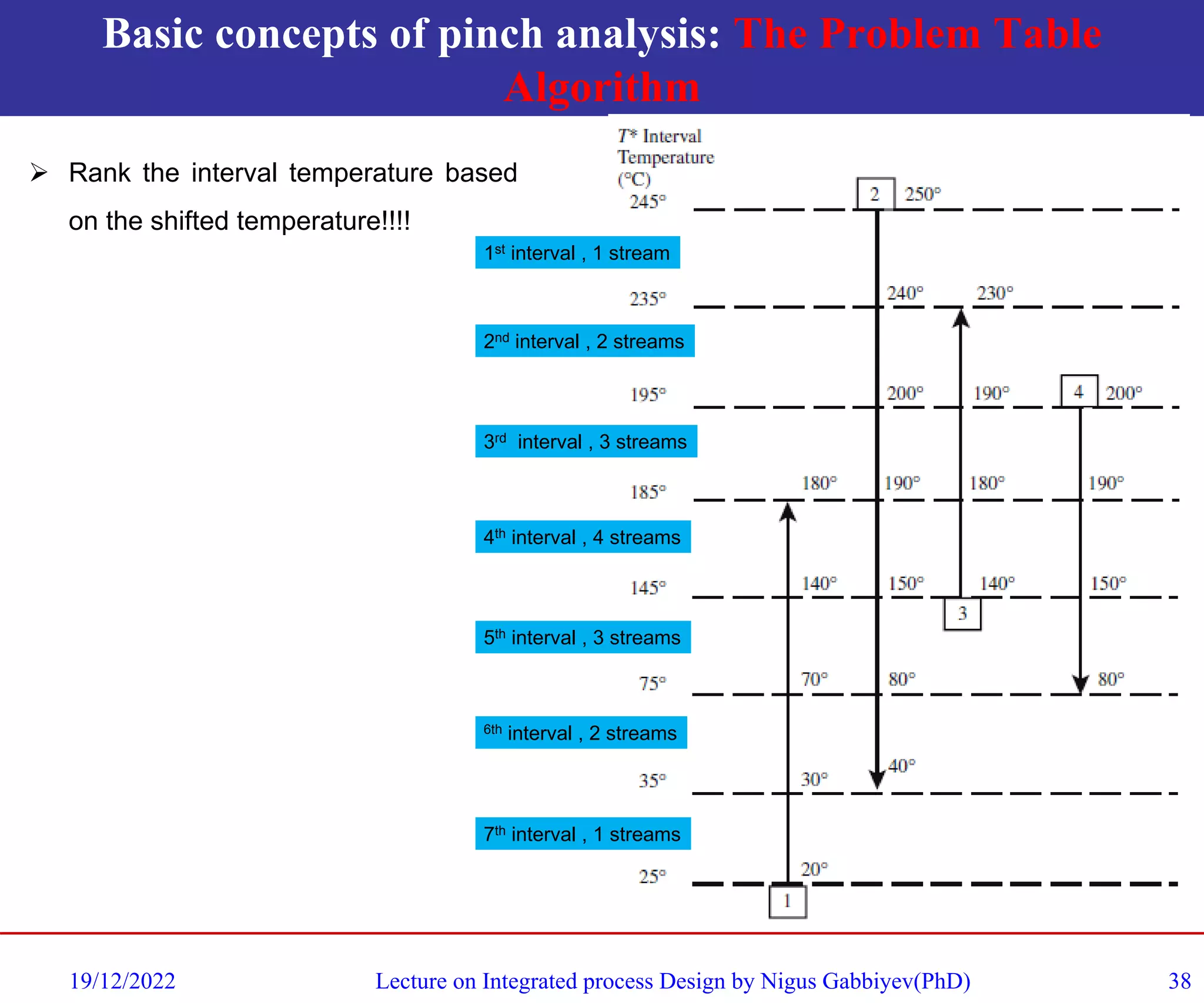
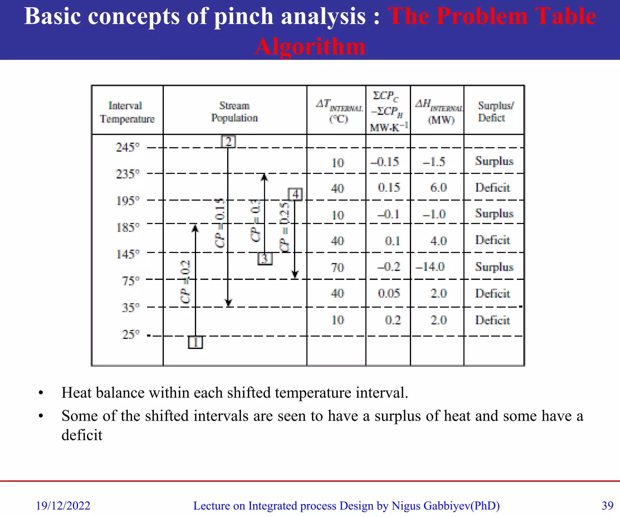
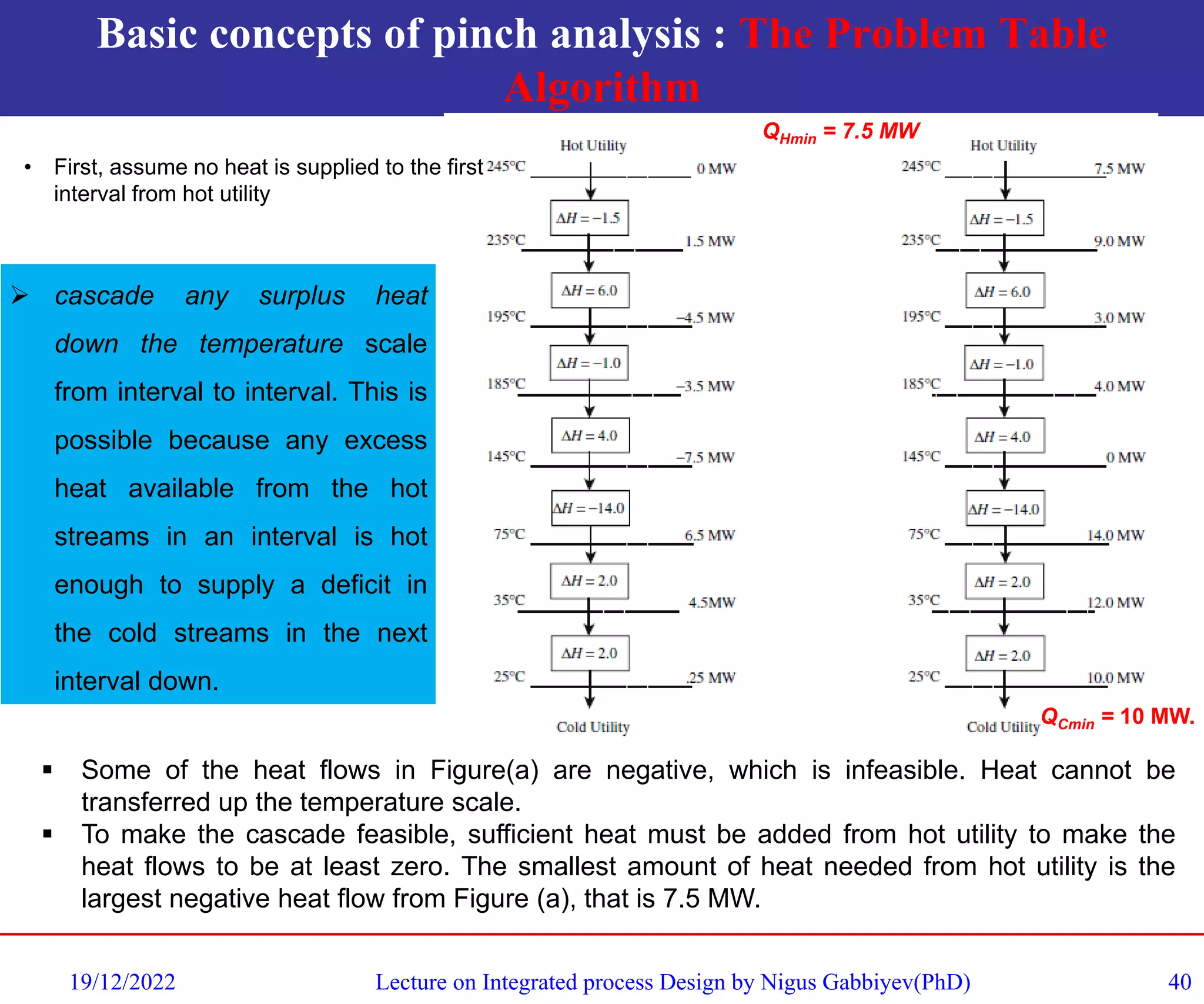
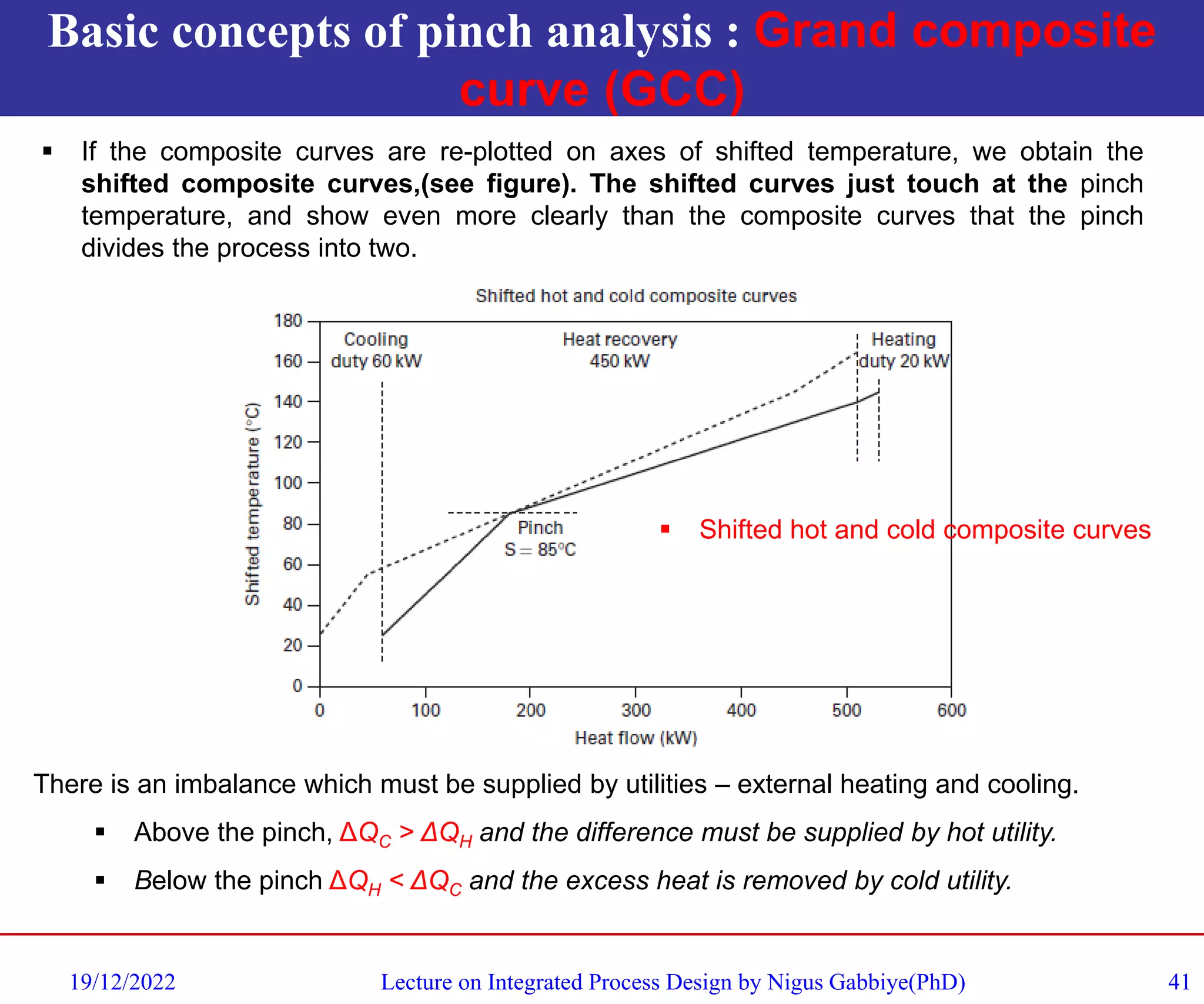
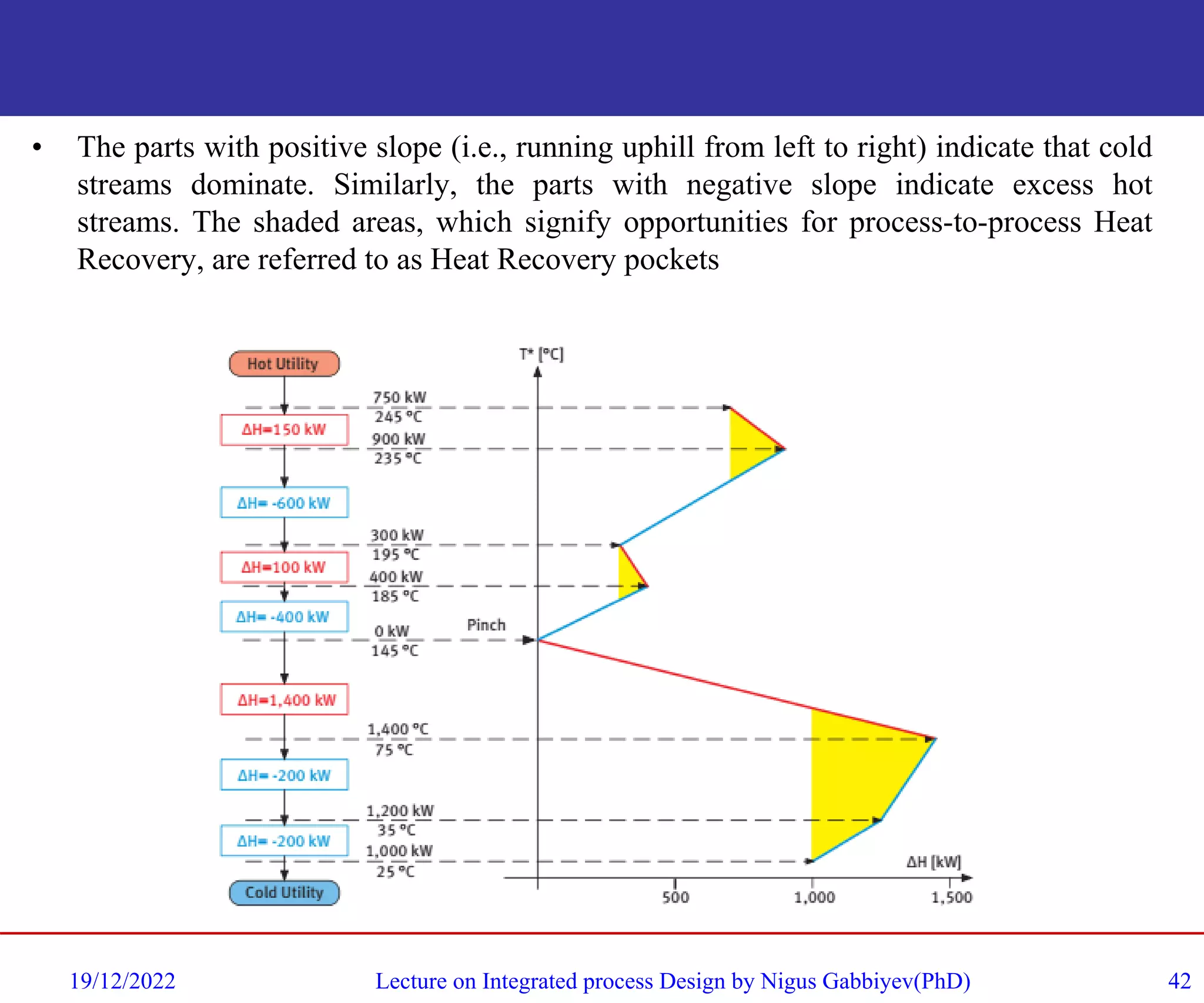
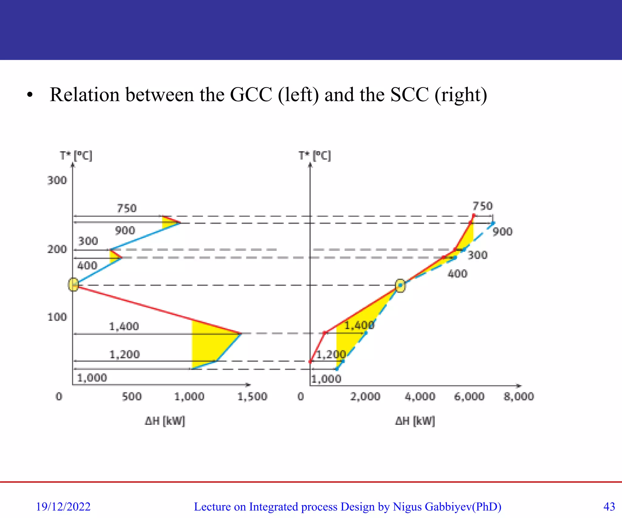
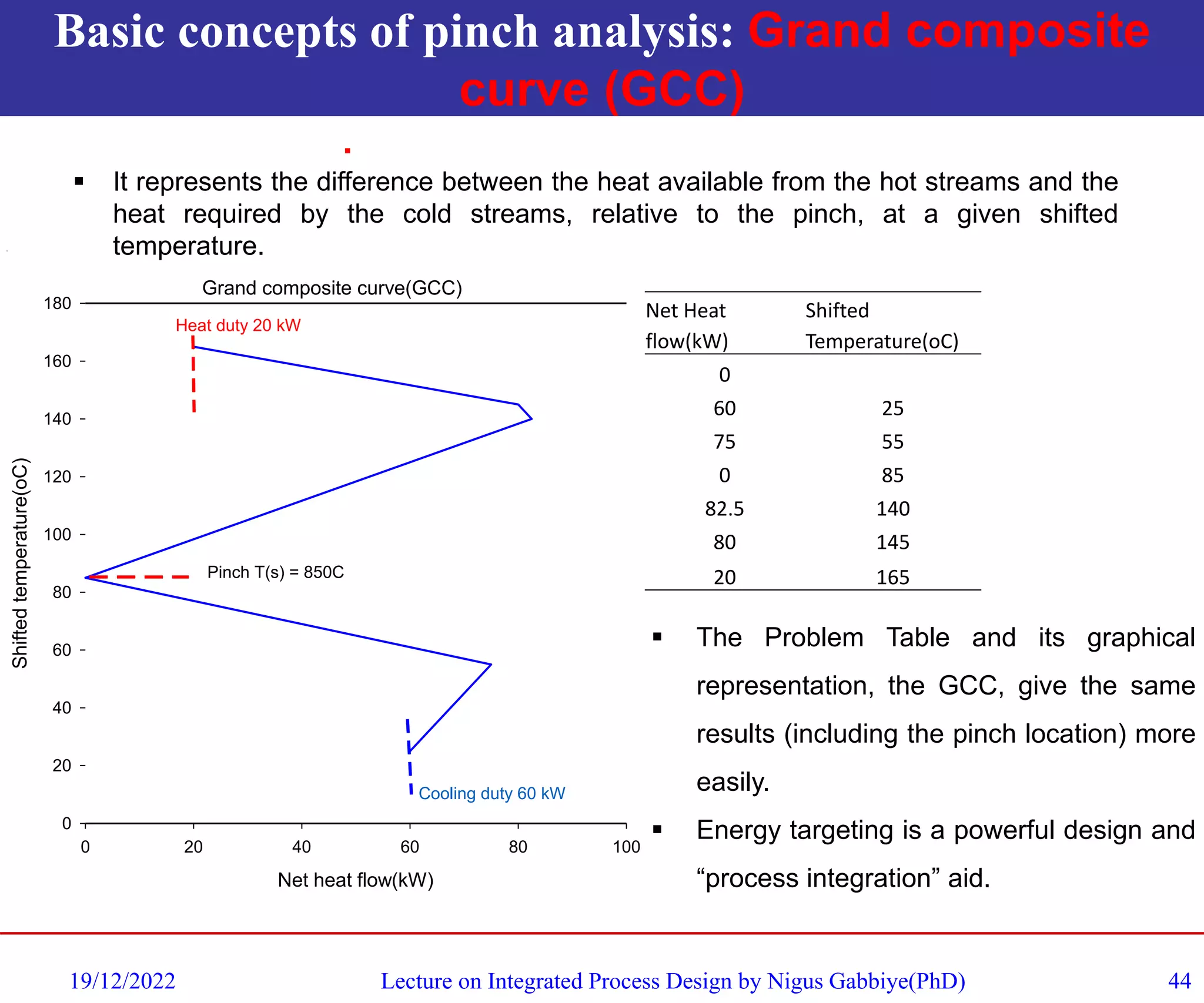
The document summarizes a lecture on pinch analysis and process integration given by Nigus Gabbiye Habtu. It discusses key concepts of pinch analysis including identifying hot and cold streams, constructing composite curves of heat sources and sinks, setting targets for minimum utility usage and capital costs, and using pinch analysis to optimize heat exchange in processes. The document provides examples of applying pinch analysis concepts to chemical reactor systems to reduce their energy demands through improved heat integration and exchange.
Most modern ammonia processes are based on steam-reforming of natural gas or naphtha.
The 3 main technology suppliers are Uhde (Uhde/JM Partnership), Topsoe & KBR.
The process steps are very similar in all cases.
Other suppliers are Linde (LAC) & Ammonia Casale.
Most modern ammonia processes are based on steam-reforming of natural gas or naphtha.
The 3 main technology suppliers are Uhde (Uhde/JM Partnership), Topsoe & KBR.
The process steps are very similar in all cases.
Other suppliers are Linde (LAC) & Ammonia Casale.
Design method for shell tube heat exchangerKarnav Rana
Design method for shell tube heat exchanger
Selection of Cooling Medium or Heating Medium
shell tube heat exchanger
Heating mediums
Cooling mediums
Energy Balance and Heat Transfer Calculations
Mean Temperature Difference
Estimation of Overall Heat Transfer Coefficient
Finding Shell Diameter
FULL COURSE:
https://courses.chemicalengineeringguy.com/p/flash-distillation-in-chemical-process-engineering/
Introduction:
Binary Distillation is one of the most important Mass Transfer Operations used extensively in the Chemical industry.
Understanding the concept behind Gas-Gas, Liquid-Liquid and the Gas-Liquid mass transfer interaction will allow you to understand and model Distillation Columns, Flashes, Batch Distillator, Tray Columns and Packed column, etc...
We will cover:
REVIEW: Of Mass Transfer Basics (Equilibrium VLE Diagrams, Volatility, Raoult's Law, Azeotropes, etc..)
Distillation Theory - Concepts and Principles
Application of Distillation in the Industry
Equipment for Flashing Systems such as Flash Drums
Design & Operation of Flash Drums
Material and Energy Balances for flash systems
Adiabatic and Isothermal Operation
Animations and Software Simulation for Flash Distillation Systems (ASPEN PLUS/HYSYS)
Theory + Solved Problem Approach:
All theory is taught and backed with exercises, solved problems, and proposed problems for homework/individual study.
At the end of the course:
You will be able to understand mass transfer mechanism and processes behind Flash Distillation.
You will be able to continue with Batch Distillation, Fractional Distillation, Continuous Distillation and further courses such as Multi-Component Distillation, Reactive Distillation and Azeotropic Distillation.
About your instructor:
I majored in Chemical Engineering with a minor in Industrial Engineering back in 2012.
I worked as a Process Design/Operation Engineer in INEOS Koln, mostly on the petrochemical area relating to naphtha treating.
There I designed and modeled several processes relating separation of isopentane/pentane mixtures, catalytic reactors and separation processes such as distillation columns, flash separation devices and transportation of tank-trucks of product.
Selection of Heat Exchanger Types
0 INTRODUCTION/PURPOSE
1 SCOPE
2 FIELD OF APPLICATION
3 DEFINITIONS
4 BACKGROUND
5 FACTORS INFLUENCING SELECTION
5.1 Type of Duty
5.2 Temperatures and Pressures
5.3 Materials of Construction 5.4 Fouling
5.5 Safety and Reliability
5.6 Repairs
5.7 Design Methods
5.8 Dimensions and Weight
5.9 Cost
5.10 GBHE Experience
6 TYPES OF EXCHANGER
6.1 Shell and Tube Exchangers
6.2 Cylindrical Graphite Block Heat Exchangers
6.3 Cubic Graphite Block Heat Exchangers
6.4 Air Cooled Heat Exchangers
6.5 Gasketed Plate and Frame
6.6 Spiral Plate
6.7 Tube in Duct
6.8 Plate-fin
6.9 Printed Circuit Heat Exchanger (PCHE)
6.10 Scraped Surface/Wiped Film Exchangers
6.11 Welded or Brazed Plate
6.12 Double Pipe
6.13 Electric Heaters
6.14 Fired Process Heaters
TABLE
(1) ADVANTAGES AND DISADVANTAGES OF DIFFERENT SHELL AND TUBE DESIGNS
FIGURES
1 ESTIMATED MAIN PLANT ITEM COSTS
2 ESTIMATED INSTALLED COSTS
3 TEMA HEAT EXCHANGER NOMENCLATURE
4 F ‘CORRECTION FACTORS' : TEMA E SHELL WITH EVEN NUMBER OF PASSE
5 SHELL AND TUBE HEAT EXCHANGER HEAD TYPES
6 GENERAL ARRANGEMENT OF A CYLINDRICAL GRAPHITE BLOCK HEAT EXCHANGER
7 EXPLODED VIEW OF A CUBIC GRAPHITE BLOCK
HEAT EXCHANGER
8 TYPICAL AIR COOLED HEAT EXCHANGER
9 GENERAL VIEW OF ONE END OF A 3-STREAM
PLATE-FIN HEAT EXCHANGER
10 TYPICAL PCHE PLATE
11 VICARB ‘COMPABLOC' EXCHANGER
12 ‘BROWN FINTUBE' MULTITUBE HEAT EXCHANGER
13 FIRED HEATER : SCHEMATICS AND NOMENCLATURE
Pre-reforming
Flow-schemes
Feed-stocks
Catalyst handling, loading & start-up
Benefits of a pre-reformer
Case studies
Effects upon primary reformer
Data analysis
Reactor temperature profiles
Catalyst management
Summary
An overview of distillation column design concepts and major design considerations. Explains distillation column design concepts, what you would provide to a professional distillation column designer, and what you can expect back from a distillation system design firm. To speak with an engineer about your distillation column project, call EPIC at 314-207-4250.
Steam Reformer Surveys - Techniques for Optimization of Primary Reformer Oper...Gerard B. Hawkins
Introduction
Background Radiation and Temperature Measurement
Reformer Survey Inputs
Other Troubleshooting Tools
Safety
Preparation
Onsite Data Collection
TWT Survey
Observation/Troubleshooting
Modelling and Analysis
Results/Outputs
Case Studies
Conclusions
Case Study 1
Case Study 2
Case Study 3
Conclusions
Design and Rating of Packed Distillation Columns
0 INTRODUCTION/PURPOSE
1 SCOPE
2 FIELD OF APPLICATION
3 DEFINITIONS
4 DESIGN PHILOSOPHY
5 PERFORMANCE GUARANTEES
6 DESCRIPTION OF PACKED COLUMN INTERNALS
7. DESIGN CALCULATIONS
7.1 Selection of Packing Size
7.2 Rough Design
7.3 Detailed Design and Rating
8 LIQUID DISTRIBUTION AND REDISTRIBUTION
8.1 Basic Concepts
8.2 Pour Point Density
8.3 Peripheral Irrigation - the Wall Zone
8.4 Distributor Levelness
8.5 Maximum Bed Height and Liquid Redistribution
9 PRACTICAL ASPECTS OF PACKED COLUMN DESIGN
9.1 Packing
9.2 Support Grid
9.3 Liquid Collector
9.4 Liquid Distributor or Redistributor
9.5 Packing Hold-down Grid
9.6 Reflux or Feed Pipe
9.7 Reboil Return Pipe
9.8 Liquid Draw-offs
9.9 Vapor Draw-offs
10 BIBLIOGRAPHY
APPENDICES
A DEFINITIONS
A.1 INTRODUCTION
A.2 MECHANICAL DEFINITIONS
A.3 PERFORMANCE DEFINITIONS
B PACKING HYDRAULICS - THE NORTON METHOD
TABLES
1 PACKING FACTORS FOR THE MORE COMMON
RANDOM PACKINGS
Design of Heat Exchanger Network for VCM Distillation Unit Using Pinch Techno...IJERA Editor
In process industries, heat exchanger networks represent an important part of the plant structure. The purpose of the networks is to maximize heat recovery, thereby lowering the overall plant costs. In process industries, during operation of any heat exchanger network (HEN), the major aim is to focus on the best performance of the network As in present condition of fuel crises is one of the major problem faced by many country & industrial utility is majorly depend on this. There is technique called process integration which is used for integrate heat within loop so optimize the given process and minimize the heating load and cooling load .In the present study of heat integration on VCM (vinyl chloride monomer) distillation unit, Heat exchanger network (HEN) is designed by using Aspen energy analyzer V8.0 software. This software implements a methodology for HEN synthesis with the use of pinch technology. Several heat integration networks are designed with different ΔT min and total annualized cost compared to obtain the optimal design. The network with a ΔT min of 90C is the most optimal where the largest energy savings are obtained with the appropriate use of utilities (Save 15.3764% for hot utilities and 47.52% for cold utilities compared with the current plant configuration). Percentage reduction in total operating cost is 18.333%. From calculation Payback Period for new design is 3.15 year. This save could be done through a plant revamp, with the addition of two heat exchangers. This improvement are done in the process associated with this technique are not due to the use of advance unit operation, but to the generation of heat integration scheme. The Pinch Design Method can be employed to give good designs in rapid time and with minimum data.
International Journal of Engineering Research and Applications (IJERA) is an open access online peer reviewed international journal that publishes research and review articles in the fields of Computer Science, Neural Networks, Electrical Engineering, Software Engineering, Information Technology, Mechanical Engineering, Chemical Engineering, Plastic Engineering, Food Technology, Textile Engineering, Nano Technology & science, Power Electronics, Electronics & Communication Engineering, Computational mathematics, Image processing, Civil Engineering, Structural Engineering, Environmental Engineering, VLSI Testing & Low Power VLSI Design etc.
Application of Pinch Technology in Refrigerator Condenser Optimization by Usi...ijtsrd
Refrigeration is the major application area of thermodynamics, in which the heat is transferred to higher temperature region from a lower temperature region. Refrigerators are the devices which produce refrigeration and the refrigerators which operate on the cycles are called refrigeration cycles. Pinch technology and computational fluid dynamics CFD is key for study the condenser and enhance the better option for new design. Pinch Analysis also known as process integration, heat integration, energy integration, or pinch technology is method for minimizing the energy costs of a process by reusing the heat energy in the process streams rather than outside utilities. Mr. Mayur B. Ramteke | Prof. S. K. Bawne "Application of Pinch Technology in Refrigerator Condenser Optimization by Using CFD" Published in International Journal of Trend in Scientific Research and Development (ijtsrd), ISSN: 2456-6470, Volume-5 | Issue-6 , October 2021, URL: https://www.ijtsrd.com/papers/ijtsrd46440.pdf Paper URL : https://www.ijtsrd.com/engineering/mechanical-engineering/46440/application-of-pinch-technology-in-refrigerator-condenser-optimization-by-using-cfd/mr-mayur-b-ramteke
This is the second in a series of 'Show and Tell' webinars from the Ofgem Strategic Innovation Fund Round 1 Discovery phase, covering the Heat projects.
Consumers need better access to low-carbon heating options which remain reliable and affordable in comparison to existing solutions. For many domestic, commercial, and industrial end consumers, heat comprises a considerable proportion of their energy bills.
There are a variety of technologies which could potentially contribute to heat decarbonisation. These include heat networks, electric and hybrid heat pumps, hydrogen, biofuels and others.
As examples, you will hear from SIF projects working on developing the gas networks to adapt to hydrogen, and electricity networks exploring the use of thermal energy storage as a source of flexibility.
The Strategic Innovation Fund (SIF) is an Ofgem programme managed in partnership with Innovate UK, part of UKRI. The SIF aims to fund network innovation that will contribute to achieving Net Zero rapidly and at lowest cost to consumers, and help transform the UK into the ‘Silicon Valley’ of energy, making it the best place for high-potential businesses to grow and scale in the energy market.
For more information on the SIF visit: www.ofgem.gov.uk/sif
Or sign-up for our newsletter here: https://ukri.innovateuk.org/ofgem-sif-subscription-sign-up
Internally heat integrated distillation column for close boiling mixure Shahbaz khan
an example of process intensification in chemical industries, where distillation is widely used seperation process , HIDiC emprove themodynamic efficiency of distillation process
Recent advances in semiconductor technology show the improvement of fabrication on
electronics appliances in terms of performance, power density and even the size. This great achievement
however led to some major problems on thermal and heat distribution of the electronic devices. This
thermal problem could reduce the efficiency and reliability of the electronic devices. In order to minimize
this thermal problem, an optimal cooling techniques need to be applied during the operation. There are
various cooling techniques have been used and one of them is passive pin fin heat sink approach. This
paper focuses on inline pin fin heat sink, which use copper material with different shapes of pin fin and a
constant 5.5W heat sources. The simulation model has been formulated using COMSOL Multiphysics
software to stimulate the pin fin design, study the thermal distribution and the maximum heat profile.
The aim of this study is to investigate the performance of the Ground-coupled heat exchanger (GCHE) using appropriate soil, Phase change material (PCM), and Horizontal type heat exchanger with vegetation. The proposed system is powered by Photovoltaic Panels (Solar energy) and a feedback-based closed loop for user input. The Closed-loop system is calibrated in order to control the velocity of the air circulating in the heat exchanger taking into account the surrounding parameters by means of IoT Architecture. The Modelling was done using SolidWorks, and simulation by ANSYS Fluent. Further, the results were analyzed by ANOVA.
A report on Economic Feasibility for a chemical Process.(For details on Appen...Parag Patil
A Report prepared for a chemical process based on its economic feasibility and safety.
Its totally an academic project!
The course was named as "Process Analysis and Simulation" at IIT Gandhinagar,.
Objective of the study is as follows: To know how to optimize the process parameters to increase the production quality given set of possible constrains for a process.
I used the ASPEN Package to do the same and some basic calculations based on a book!
Abstract The requirement of energy in any processing industry is not only a need but it is indeed a most wanted utility. In a typical processing or manufacturing industry the most common utility are steam and cooling water. However the cost of these utility are no longer cheap, in fact they are expensive. Therefore saving these utility or minimizing the usage of these utilities is one of the most needed practice in a processing industry. Pinch technology is the most common method, which is aimed at minimizing the requirement of utilities by maximizing the process to process heat transfer. In the present study temperature interval diagram or TID is used to identify the targets for minimum utility requirement and maximum process to process heat transfer in a processing facility. The targets for heat exchanger network are presented and minimization of number of heat exchangers are provided using stream splitting technique. Keywords: Pinch design, stream splitting, HEN synthesis, Utilities, TID
Heat Transfer Characteristics of a Plate Fin Heat Sink with Pin Fins of Vario...ijtsrd
In recent decades, attempts have been made to create more advanced effective cooling technology for electronic and microelectronic devices, but heat dissipation is still a major challenge for increasing the cooling performance of heat sinks in a highly competitive electronics market. In the present analysis, the research is designing a new thermal design for plate fin heat sinks with hexagonal pin fin connected to the plate fins. A theoretical analysis focused on publicly usable computational fluid dynamics CFD codes has been performed to test the thermal efficiency of the proposed designs. Modelling done using ANSYS 14.5 and meshing has done using ICEM CFD software, simulations has done by using CFD FLUENT software. In specific, in terms of their thermal performance, hexagonal pin fin connected to the plate fins subject to flow have been contrasted. The plate fin heat sink was made of Aluminium and an electrical heaters provide a heat of 10W constantly to warm up a plate plate fin heat sink with hexagonal pin fin subject to flow of air at variable values i.e. 6.5, 9.5, and 2.5 m s .Based on the results, the analysis has shown that the plate fin heat sinks demonstrate superior thermal performance with hexagonal 3 pin fin subject to flow. The Nusselt number is approximately 1.32 times higher than the conventional plate fin heat sink without pin fin and 1.13 times higher than plate fin heat sink with elliptical 3 pin fin. Prof. Pushparaj Singh | Prashant Kumar Pandey "Heat Transfer Characteristics of a Plate Fin Heat Sink with Pin Fins of Various Profile using CFD" Published in International Journal of Trend in Scientific Research and Development (ijtsrd), ISSN: 2456-6470, Volume-4 | Issue-6 , October 2020, URL: https://www.ijtsrd.com/papers/ijtsrd33375.pdf Paper Url: https://www.ijtsrd.com/engineering/mechanical-engineering/33375/heat-transfer-characteristics-of-a-plate-fin-heat-sink-with-pin-fins-of-various-profile-using-cfd/prof-pushparaj-singh
REMOURBAN Information package n2 - Low Temperature District Heating (LTDH)REMOURBAN
The Nottingham City Council aims to create a citywide heat network that will further enable Nottingham to cope with climate change and build resilience to external energy price pressures.
5 heat exchanger thermal design of oil system for turbo centrifugal compresso...IJCMESJOURNAL
A thermal management is vital issues of all energy equipment such as compressor, gas turbine, and boilers etc. The compressor is generally used in power, oil & gas, air separation, and chemical plant. It is consist of air or gas compression part, gear, bearing, cooling, sealing, lube oil, and control system. In this study focused on heat exchanger for oil supply systems. Lube oil is very important to supply oil and protect bearing. Lube oil’s temperature control is vital issue to prevent system broken. Shell and tube heat exchanger is used as a cooler. In this study, HTRI Xist used to thermal design of oil cooler, with water and nanofluid. The thermal conductivity is ~9.3% higher than water. The tube side overall heat transfer coefficient of nanofluid is increased by ~9% compared to that of water.
Paper Statistics:
An Approach to Detecting Writing Styles Based on Clustering Techniquesambekarshweta25
An Approach to Detecting Writing Styles Based on Clustering Techniques
Authors:
-Devkinandan Jagtap
-Shweta Ambekar
-Harshit Singh
-Nakul Sharma (Assistant Professor)
Institution:
VIIT Pune, India
Abstract:
This paper proposes a system to differentiate between human-generated and AI-generated texts using stylometric analysis. The system analyzes text files and classifies writing styles by employing various clustering algorithms, such as k-means, k-means++, hierarchical, and DBSCAN. The effectiveness of these algorithms is measured using silhouette scores. The system successfully identifies distinct writing styles within documents, demonstrating its potential for plagiarism detection.
Introduction:
Stylometry, the study of linguistic and structural features in texts, is used for tasks like plagiarism detection, genre separation, and author verification. This paper leverages stylometric analysis to identify different writing styles and improve plagiarism detection methods.
Methodology:
The system includes data collection, preprocessing, feature extraction, dimensional reduction, machine learning models for clustering, and performance comparison using silhouette scores. Feature extraction focuses on lexical features, vocabulary richness, and readability scores. The study uses a small dataset of texts from various authors and employs algorithms like k-means, k-means++, hierarchical clustering, and DBSCAN for clustering.
Results:
Experiments show that the system effectively identifies writing styles, with silhouette scores indicating reasonable to strong clustering when k=2. As the number of clusters increases, the silhouette scores decrease, indicating a drop in accuracy. K-means and k-means++ perform similarly, while hierarchical clustering is less optimized.
Conclusion and Future Work:
The system works well for distinguishing writing styles with two clusters but becomes less accurate as the number of clusters increases. Future research could focus on adding more parameters and optimizing the methodology to improve accuracy with higher cluster values. This system can enhance existing plagiarism detection tools, especially in academic settings.
NO1 Uk best vashikaran specialist in delhi vashikaran baba near me online vas...Amil Baba Dawood bangali
Contact with Dawood Bhai Just call on +92322-6382012 and we'll help you. We'll solve all your problems within 12 to 24 hours and with 101% guarantee and with astrology systematic. If you want to take any personal or professional advice then also you can call us on +92322-6382012 , ONLINE LOVE PROBLEM & Other all types of Daily Life Problem's.Then CALL or WHATSAPP us on +92322-6382012 and Get all these problems solutions here by Amil Baba DAWOOD BANGALI
#vashikaranspecialist #astrologer #palmistry #amliyaat #taweez #manpasandshadi #horoscope #spiritual #lovelife #lovespell #marriagespell#aamilbabainpakistan #amilbabainkarachi #powerfullblackmagicspell #kalajadumantarspecialist #realamilbaba #AmilbabainPakistan #astrologerincanada #astrologerindubai #lovespellsmaster #kalajaduspecialist #lovespellsthatwork #aamilbabainlahore#blackmagicformarriage #aamilbaba #kalajadu #kalailam #taweez #wazifaexpert #jadumantar #vashikaranspecialist #astrologer #palmistry #amliyaat #taweez #manpasandshadi #horoscope #spiritual #lovelife #lovespell #marriagespell#aamilbabainpakistan #amilbabainkarachi #powerfullblackmagicspell #kalajadumantarspecialist #realamilbaba #AmilbabainPakistan #astrologerincanada #astrologerindubai #lovespellsmaster #kalajaduspecialist #lovespellsthatwork #aamilbabainlahore #blackmagicforlove #blackmagicformarriage #aamilbaba #kalajadu #kalailam #taweez #wazifaexpert #jadumantar #vashikaranspecialist #astrologer #palmistry #amliyaat #taweez #manpasandshadi #horoscope #spiritual #lovelife #lovespell #marriagespell#aamilbabainpakistan #amilbabainkarachi #powerfullblackmagicspell #kalajadumantarspecialist #realamilbaba #AmilbabainPakistan #astrologerincanada #astrologerindubai #lovespellsmaster #kalajaduspecialist #lovespellsthatwork #aamilbabainlahore #Amilbabainuk #amilbabainspain #amilbabaindubai #Amilbabainnorway #amilbabainkrachi #amilbabainlahore #amilbabaingujranwalan #amilbabainislamabad
Understanding Inductive Bias in Machine LearningSUTEJAS
This presentation explores the concept of inductive bias in machine learning. It explains how algorithms come with built-in assumptions and preferences that guide the learning process. You'll learn about the different types of inductive bias and how they can impact the performance and generalizability of machine learning models.
The presentation also covers the positive and negative aspects of inductive bias, along with strategies for mitigating potential drawbacks. We'll explore examples of how bias manifests in algorithms like neural networks and decision trees.
By understanding inductive bias, you can gain valuable insights into how machine learning models work and make informed decisions when building and deploying them.
Cosmetic shop management system project report.pdfKamal Acharya
Buying new cosmetic products is difficult. It can even be scary for those who have sensitive skin and are prone to skin trouble. The information needed to alleviate this problem is on the back of each product, but it's thought to interpret those ingredient lists unless you have a background in chemistry.
Instead of buying and hoping for the best, we can use data science to help us predict which products may be good fits for us. It includes various function programs to do the above mentioned tasks.
Data file handling has been effectively used in the program.
The automated cosmetic shop management system should deal with the automation of general workflow and administration process of the shop. The main processes of the system focus on customer's request where the system is able to search the most appropriate products and deliver it to the customers. It should help the employees to quickly identify the list of cosmetic product that have reached the minimum quantity and also keep a track of expired date for each cosmetic product. It should help the employees to find the rack number in which the product is placed.It is also Faster and more efficient way.
NUMERICAL SIMULATIONS OF HEAT AND MASS TRANSFER IN CONDENSING HEAT EXCHANGERS...ssuser7dcef0
Power plants release a large amount of water vapor into the
atmosphere through the stack. The flue gas can be a potential
source for obtaining much needed cooling water for a power
plant. If a power plant could recover and reuse a portion of this
moisture, it could reduce its total cooling water intake
requirement. One of the most practical way to recover water
from flue gas is to use a condensing heat exchanger. The power
plant could also recover latent heat due to condensation as well
as sensible heat due to lowering the flue gas exit temperature.
Additionally, harmful acids released from the stack can be
reduced in a condensing heat exchanger by acid condensation. reduced in a condensing heat exchanger by acid condensation.
Condensation of vapors in flue gas is a complicated
phenomenon since heat and mass transfer of water vapor and
various acids simultaneously occur in the presence of noncondensable
gases such as nitrogen and oxygen. Design of a
condenser depends on the knowledge and understanding of the
heat and mass transfer processes. A computer program for
numerical simulations of water (H2O) and sulfuric acid (H2SO4)
condensation in a flue gas condensing heat exchanger was
developed using MATLAB. Governing equations based on
mass and energy balances for the system were derived to
predict variables such as flue gas exit temperature, cooling
water outlet temperature, mole fraction and condensation rates
of water and sulfuric acid vapors. The equations were solved
using an iterative solution technique with calculations of heat
and mass transfer coefficients and physical properties.
Saudi Arabia stands as a titan in the global energy landscape, renowned for its abundant oil and gas resources. It's the largest exporter of petroleum and holds some of the world's most significant reserves. Let's delve into the top 10 oil and gas projects shaping Saudi Arabia's energy future in 2024.
Sachpazis:Terzaghi Bearing Capacity Estimation in simple terms with Calculati...Dr.Costas Sachpazis
Terzaghi's soil bearing capacity theory, developed by Karl Terzaghi, is a fundamental principle in geotechnical engineering used to determine the bearing capacity of shallow foundations. This theory provides a method to calculate the ultimate bearing capacity of soil, which is the maximum load per unit area that the soil can support without undergoing shear failure. The Calculation HTML Code included.
Sachpazis:Terzaghi Bearing Capacity Estimation in simple terms with Calculati...
Lecture-III Basics of Pinch Analysis.pdf
1. Lecture –III
Pinch Analysis and Process Integration
Nigus Gabbiye Habtu (PhD)
2015E.C
Faculty of
Chemical and Food Engineering
Bahir Dar Institute
of Technology
2. Heat Exchanger Networks
19/12/2022 Lecture on Integrated Process Design by Nigus Gabbiye(PhD) 2
❑ Why Does Pinch Analysis Work?
▄ Approach in Pinch Analysis
▪ Thermodynamic Approach
▪ Energy Targets and Solution/Design
─ The Composite method
─ Grand composite curves
─ The problem table Algorithm
▪ Capital and Total Cost Targets
3. Pinch Technology and targeting Heat Recovery: the
thermodynamic roots
• Heat Recovery can be used to provide either heating or cooling to
processes to replace hot or cold utilities.
– It is widely applied in industry and has an extensive historical record.
– Systematic methods for performing Heat Recovery have emerged in
the last 40 years inspired by the 1970s oil crises
• Heat Recovery may take various forms:
– transferring heat between process streams,
– generating steam from higher temperature process waste heat,
– preheating a service stream (air for a furnace, as well as air
or feed water for a boiler) by using excess process heat.
• Heat Exchanger Networks (HEN) synthesis – one of the very important
and common tasks of process design – has become the starting point for
the Process Integration revolution in industrial systems design
19/12/2022 Lecture on Integrated process Design by Nigus Gabbiyev(PhD) 3
❑ Why Does Pinch Analysis Work?
4. Pinch Technology and targeting Heat Recovery: the
thermodynamic roots
19/12/2022 Lecture on Integrated process Design by Nigus Gabbiyev(PhD) 4
▪ A hot process stream can
supply heat to a cold one
when paired: Heat Exchange
matches
Heat Exchanger Matches
➢ Heat Recovery Pinch concept (discovered Linnhoff and Flower, 1978)
was a critical step in the development of HEN synthesis.
5. Pinch Technology and targeting Heat Recovery: the
thermodynamic roots
• The main idea behind the formulated procedure was to obtain – prior
to the core design steps – guidelines and targets for HEN
performance.
• The hot and cold streams for the process under consideration are
combined to yield
1) a Hot Composite Curve collectively representing the process
• heat sources (the hot streams);
2) a Cold Composite Curve representing in a similar way the
process
• heat sinks (the cold streams)
19/12/2022 Lecture on Integrated process Design by Nigus Gabbiyev(PhD) 5
• This procedure is possible through thermodynamics
principles.
How?
6. What is pinch analysis?
• The analysis of the heat exchanger network:
– First identifies sources of heat (termed hot streams)
– Second identifies sources of sinks (termed cold streams)
19/12/2022 Lecture on Integrated process Design by Nigus Gabbiyev(PhD) 6
The material
and energy
balance.
▪ Targets can be set for the heat exchanger network to assess the performance of the
complete process design without actually having to carry out the network design.
▪ These targets allow both energy and capital cost for the heat exchanger network
to be assessed.
▪ The targets allow the designer to suggest process changes for the reactor and
separation and recycle systems to improve the targets for energy and capital cost of
the heat exchanger network( Onion Model)
7. What is pinch analysis?
• The second law of thermodynamics implies that heat flows from higher
temperature to lower temperature locations.
– In a heat exchanger the required heat transfer area is proportional to the
temperature difference between the streams.
19/12/2022 Lecture on Integrated process Design by Nigus Gabbiyev(PhD) 7
Figure: Thermodynamic limits on Heat Recovery
• In heat exchanger design, the minimum
allowed temperature difference (ΔTmin) is the
lower bound on any temperature differences
to be encountered in any heat exchanger in
the network
▪ The value of ΔTmin is a design parameter
determined by exploring the trade-offs
between more Heat Recovery and the larger
heat transfer area requirement
1. Heat Recovery = 10 MW, for ΔTmin = 20 °C.
2. Heat Recovery = 11 MW for ΔTmin = 10 °C
More hear is possible to “squeeze out” by lowering the temperature difference
8. What is pinch analysis? Conceptually!!!!
• When designing heat exchangers and other unit operations, limitations imposed
by the first and second laws of thermodynamics constrain what can be done
with such equipment.
– For example, in a heat exchanger, a close approach between hot and cold
streams requires a large heat transfer area.
19/12/2022 Lecture on Integrated process Design by Nigus Gabbiyev(PhD) 8
Pinch point
➢ Whenever the driving forces for heat or mass exchange are small, the equipment needed
for transfer becomes large and it is said that the design has a pinch.
9. What is pinch analysis?
• Likewise, in a distillation column, as the reflux ratio approaches the
minimum value for a given separation, the number of equilibrium
stages becomes very large.
19/12/2022 Lecture on Integrated process Design by Nigus Gabbiyev(PhD) 9
• .
• The intersection of an operating line and the equilibrium curve
is called a pinch point
10. What is pinch analysis?
19/12/2022 Lecture on Integrated Process Design by Nigus Gabbiye(PhD) 10
▪ The pinch point is the location in the heat exchanger where the temperature
difference between hot and cold fluid is minimum at that location.
The pinch point is important for analyzing heat transfer in thermodynamic
cycles
Definition
➢ When considering systems of many
heat- or mass-exchange devices
(called exchanger networks), there
will exist somewhere in the system a
point where the driving force for
energy or mass exchange is a
minimum. This represents a pinch or
pinch point.
11. What is pinch analysis?
19/12/2022 Lecture on Integrated Process Design by Nigus Gabbiye(PhD) 11
• The general algorithm is presented to give the minimum number of
exchangers requiring the minimum utility requirements for a given
minimum approach temperature.
▪ Pinch analysis is a methodology for minimizing energy consumption of
chemical processes by calculating thermodynamically feasible energy
targets (or minimum energy consumption) and achieving them by
optimizing heat recovery systems, energy supply methods
and process operating condition
➢ Pinch analysis is based on straightforward thermodynamics, and uses it in a
practical way. However, the approach is largely non-mathematical.
12. What is pinch analysis?
19/12/2022 Lecture on Integrated Process Design by Nigus Gabbiye(PhD) 12
▪ The first key concept of pinch analysis is setting energy / temperature
targets. “Targets” for energy reduction have been a key part of energy
monitoring schemes for many years.
▪ Typically, a reduction in plant energy consumption of 10% per year is
demanded.
• The successful design of these networks involves defining where the
pinch exists and using the information at the pinch point to design the
whole network. This design process is designed as pinch technology
• The concepts of pinch technology can be applied to a wide variety of
problems in heat and mass transfer
1. Heat exchanger networks (HENs)
2. mass-exchanger networks (MENs)
13. What is pinch analysis?
• What is the difference between the two reactor systems??
– the way in which the heat exchange takes place
19/12/2022 Lecture on Integrated process Design by Nigus Gabbiyev(PhD) 13
a) Without Heat Integration, b) With Heat Integration
• The savings received over the life of the plant by using heat integration are (–
471,000 + 1,636,000) = $1,165,000!
The heat integration saves money in two ways:
(1) The cooling water utility is reduced and the high-pressure steam is eliminated,
(2) Heat exchanger E-203 is smaller because the duty is reduced, and E-202 is also
smaller due to the fact that hps condenses at 254°C
DME Reactor Feed and Effluent Heat Exchange System
14. Basic concepts of pinch analysis system
19/12/2022 Lecture on Integrated Process Design by Nigus Gabbiye(PhD) 14
Consider this process(chemical reactor system with heating & cooling
requirements)
Definitions:
▪ The feed, which starts cold and needs to be heated
up, is known as a cold stream.
▪ The hot product which must be cooled down is called
a hot stream.
Mass
flowrate
W(kg/s)
Specific heat
capacity
Cp (kI/kgK)
Hheat
capacity
flowrate
Cp (kW/K)
Initial
Temperature
Ts(oC)
Final/Target
Temperature
Ts(oC)
Heat Load
H(kW)
Cold stream 0.25 4 1.0 20 200 -180
Hot stream 0.4 4.5 1.8 150 50 +180
Stream information
❑ How do you supply those heat loads??
▪ By external heating and cooling! What else???
15. Basic concepts of pinch analysis system
19/12/2022 Lecture on Integrated Process Design by Nigus Gabbiye(PhD) 15
Can we reduce energy consumption?
▪ Yes; if we can recover some heat from the hot stream and use it to
heat the cold stream in a heat exchanger, we will need less steam
and water to satisfy the remaining duties.
▪ Ideally we can
extract all of
180kW to heat the
cold stream
Cold stream
Heat stream
▪ This is not possible because of temperature limitations.
▪ By the Second Law of Thermodynamics, we can’t use a hot stream at
150°C to heat a cold stream at 200°C!
16. Basic concepts of Pinch: Data extraction
Data extraction: Heat Recovery problem identification
• For efficient Heat Recovery in industry, the relevant data must be identified
and presented systematically.
– In the field of Heat Integration, this process is referred to as data extraction
• The Heat Recovery problem data are extracted in several steps.
1. Inspect the general process flowsheet, which may contain Heat Recovery
exchangers.
2. Remove the recovery heat exchangers and replace them with equivalent
“virtual” heaters and coolers.
3. Lump all consecutive heaters and coolers.
4. The resulting virtual heaters and coolers represent the net heating and
cooling demands of the flowsheet streams.
5. The heating and cooling demands of the flowsheet streams are then listed
in a tabular format, where each heating demand is referred to as a cold
stream and, conversely, each cooling demand as a hot stream.
19/12/2022 Lecture on Integrated process Design by Nigus Gabbiyev(PhD) 16
17. Basic concepts of Pinch: Data extraction
19/12/2022 Lecture on Integrated process Design by Nigus Gabbiyev(PhD) 17
Class Activities: Flowsheet with two hot streams and two cold streams
Product 1
40ºC
Coln
40ºC
Off Gas
Reactor 2
ΔH=-30 MW
Reactor 1
Feed 2
80ºC
200ºC
180ºC
230ºC
20ºC
140ºC
250ºC
Product 2
Feed 1
ΔH=27 MW
ΔH=32 MW
ΔH=-31.5 MW
40ºC
o Total hot streams heat duty =
61.5 MW (Surplus)
o Total cold streams heat duty =
59 MW (Deficit)
1. Tabulate the four streams
2. Generate the composite curve
of those data
18. Basic concepts of pinch analysis system
• Basic concepts of heat exchange: The temperature–enthalpy diagram:
19/12/2022 Lecture on Integrated process Design by Nigus Gabbiyev(PhD) 18
For constant CP
➢ the slope of the line
representing the stream is:
19. Basic concepts of pinch analysis system:
The temperature–enthalpy diagram:
• The general algorithm is presented to give the minimum number of
exchangers requiring the minimum utility requirements for a given minimum
approach temperature.
1. Choose a minimum approach temperature. This is part of a
parametric optimization
2. Construct a temperature interval diagram.
3. Construct a cascade diagram, and determine the minimum utility
requirements and the pinch temperatures.
4. Calculate the minimum number of heat exchangers above and below
the pinch.
5. Construct the heat-exchanger network
19/12/2022 Lecture on Integrated process Design by Nigus Gabbiyev(PhD) 19
20. Basic concepts of pinch analysis system:
The temperature–enthalpy diagram
19/12/2022 Lecture on Integrated Process Design by Nigus Gabbiye(PhD) 20
➢ The T/H diagram can be used to represent heat exchange:
➢ For feasible heat exchange between the two, the hot stream must at all
points be hotter than the cold stream, vis versal is also true
T/H diagram with ΔTmin 0°C
• How big the heat
exchanger will determine
the overall cost
21. Basic concepts of pinch analysis system:
The temperature–enthalpy diagram:
19/12/2022 Lecture on Integrated Process Design by Nigus Gabbiye(PhD) 21
T/H diagram with ΔTmin 20°C
▪ The cold stream is shifted on the H-axis
relative to the hot stream so that the
minimum temperature difference, ΔTmin is
20°C.
▪ The effect of this shift is to increase the
utility heating and cooling by equal
amounts and reduce the load on the
exchanger by the same amount – here 20
kW – so that 70 kW of external heating
and cooling is required
Two basic facts are emerge.
1. There is a correlation between the value of ΔTmin in the exchanger and the total utility load
on the system. This means that if we choose a value of ΔTmin, we have an energy target
for how much heating and cooling we should be using if we design our heat exchanger
correctly.
2. If the hot utility load is increased by any value α, the cold utility is increased by α as well. As
the stream heat loads are constant, this also means that the heat exchanged falls by α.
22. Basic concepts of pinch analysis system:
The composite Curve(Multiple streams)
19/12/2022 Lecture on Integrated Process Design by Nigus Gabbiye(PhD) 22
▪ To handle multiple streams, we add together the heat loads or heat capacity
flow rates of all streams existing over any given temperature range.
▪ A single composite of all hot streams
▪ A single composite of all cold streams can be produced in the T/H
diagram,
23. Basic concepts of pinch analysis system: The composite
Curve(Multiple streams)
• a composite segment is formed consisting of:
1. a temperature difference equal to that of the interval
2. a total cooling requirement equal to the sum of the cooling
requirements of all streams within the interval by summing up
the heat capacity flow rates of the streams
19/12/2022 Lecture on Integrated process Design by Nigus Gabbiyev(PhD) 23
Add up
∆H1 = CPA(T1-T2);
∆H2 = (CPA +CPB+ CPC)(T2-T3);
∆H3 = (CPA+CPC)(T3-T4);
∆H4 = (CPA(T4-T5)
▪ The resulting T/H plot is a single
curve representing all the hot
streams, known as the hot
composite curve
➢ A similar procedure gives a cold composite curve of all the cold streams in a problem
24. Basic concepts of pinch analysis system: The composite
Curve(Multiple streams)
• Cold and hot Composite Curves are combined in the same plot in order to
identify the maximum overlap, which represents the maximum amount of heat
that could be recovered. The HCC and CCC for following data
19/12/2022 Lecture on Integrated process Design by Nigus Gabbiyev(PhD) 24
• The overlap between the two Composite Curve s on the Heat
Exchange axis represents the Heat Recovery target – i.e. the
maximum amount of process heat being internally recovered
▪ The targets for external
(utility) heating and
cooling are represented
by the non-overlapping
segments of the Cold
and Hot Composite
Curves.
25. Basic concepts of pinch analysis system: The composite
Curve(Multiple streams)
• Both CCs can be moved horizontally (i.e., along the ΔH axis), but usually the
HCC position is fixed and the CCC is shifted. This is equivalent to varying the
amount of Heat Recovery and (simultaneously) the amount of required utility
heating and cooling. Where the curves overlap, heat can be recovered between
the hot and cold streams. More overlap means more Heat Recovery and smaller
utility requirements, and vice versa.
19/12/2022 Lecture on Integrated process Design by Nigus Gabbiyev(PhD) 25
26. Basic concepts of pinch analysis system: The composite
Curve(Multiple streams)
• The appropriate value for ΔTmin is determined by economic trade-offs.
Increasing ΔTmin results in larger minimum utility demands and increased
energy costs; choosing a higher value reflects the need to reduce heat transfer
area and its corresponding investment cost. Conversely, if ΔTmin is reduced
then utility costs go down but investment costs go up.
19/12/2022 Lecture on Integrated process Design by Nigus Gabbiyev(PhD) 26
➢ Trade-off is illustration for
maximum heat recovery and
capital cost.
▪ How much energy can we extract?
▪ How big should the exchanger be
▪ What will be the temperatures around it?
27. Basic concepts of pinch analysis system: The composite
Curve(Multiple streams)
• Example -2: A typical pair of composite curves for the four-stream
given in Table below.
19/12/2022 Lecture on Integrated process Design by Nigus Gabbiyev(PhD) 27
▪ Overlap between the composite curves represents the maximum amount of heat recovery possible
▪ Overshoot at the bottom represents the minimum amount of external cooling required
▪ Overshoot at the top represents the minimum amount of external heating required
28. Basic concepts of heat exchange: The composite
Curve(Multiple streams)
➢ There are three possible ways of moving the hot and cold composite
curves closer together by ΔTmin, so that they touch at the pinch.
1. Express all temperatures in terms of hot stream temperatures and
increase all cold stream temperatures by ΔTmin.
2. Express all temperatures in terms of cold stream temperatures and
reduce all hot stream temperatures by ΔTmin.
3. Use the shifted temperatures, which are a mean value; all hot stream
temperatures are reduced by ΔTmin/2 and all cold stream temperatures
are increased by ΔTmin/2.
19/12/2022 Lecture on Integrated process Design by Nigus Gabbiyev(PhD) 28
➢ Approach 3 has been the most commonly adopted, we will follow for
designing of the heat exchanger network
29. Basic concepts of pinch analysis system: The Problem
Table Algorithm
19/12/2022 Lecture on Integrated Process Design by Nigus Gabbiye(PhD) 29
▪ It is the preferred method, avoiding the need to draw the composite
curves and maneuver the composite cooling curve using, for example,
tracing paper or cut-outs, to give the chosen minimum temperature
difference on the diagram.
▪ The Composite Curves are a useful tool for visualising Heat Recovery
targets. However, they can be time consuming to draw for problems that
involve many process streams. In addition, targeting that relies solely on
such graphical techniques cannot be very precise.
▪ A method of calculating energy targets directly without the necessity of
graphical construction is called the Problem Table Algorithm(Linnhoff
and Flower (1978)
▪ It provides pinch temperatures and the minimum utility requirements;
30. Basic concepts of pinch analysis system: The Problem
Table Algorithm
• The steps are as follows:
1. Shift the process stream temperatures.
2. Set up temperature intervals.
3. Calculate interval heat balances.
4. Assuming zero hot utility, cascade the balances
as heat flows.
5. Ensure positive heat flows by increasing the hot
utility as needed.
19/12/2022 Lecture on Integrated process Design by Nigus Gabbiyev(PhD) 30
31. Basic concepts of pinch analysis: The Problem Table
Algorithm
The procedure follows
1. Convert the actual stream temperatures Tact into interval temperatures
Tint by subtracting half the minimum temperature difference(ΔTmin)
from the hot stream temperatures, and by adding half to the cold
stream temperatures:
19/12/2022 Lecture on Integrated process Design by Nigus Gabbiyev(PhD) 31
➢ The use of the interval temperature rather than the actual temperatures allows the minimum
temperature difference to be taken into account. ∆Tmin = 10oC for the problem being
considered;
Example: Table 2: Interval temperatures for ∆Tmin = 10°C
32. Basic concepts of pinch analysis : The Problem Table
Algorithm
19/12/2022 Lecture on Integrated process Design by Nigus Gabbiyev(PhD) 32
➢ The amount that can be recovered depends on the relative slopes of the
two curves in the temperature interval.
➢ This problem can be overcome if, purely for the purposes of construction, the
hot composite is shifted to be ∆Tmin /2 colder than it is in practice and that the
cold composite is shifted to be ∆ Tmin /2 hotter than it is in practice as shown
in Figure b. The shifted composite curves now touch at the pinch.
33. Basic concepts of pinch analysis: The Problem Table
Algorithm
2. Rank the interval temperatures in order of magnitude, showing the duplicated
temperatures only once in the order. Temperature intervals are formed by listing all
shifted process stream temperatures in descending order.
19/12/2022 Lecture on Integrated process Design by Nigus Gabbiyev(PhD) 33
Example: Table 3: Interval temperatures for ∆Tmin = 10°C
34. Basic concepts of pinch analysis: The Problem Table
Algorithm
19/12/2022 Lecture on Integrated Process Design by Nigus Gabbiye(PhD) 34
3. Carry out a heat balance for the streams falling within each temperature
interval: For the nth interval:
Where:-
➢ First, the stream population of the process segments falling within each
temperature interval (the second two columns of Table 3) is identified. The
sums of the segment CPs (heat capacity flow rates) in each interval are
calculated; then that sum is multiplied by the interval temperature difference
(i.e., the difference between the TBs that define each interval). This
calculation is also illustrated in Table 3
35. Basic concepts of pinch analysis : The Problem Table
Algorithm
19/12/2022 Lecture on Integrated Process Design by Nigus Gabbiye(PhD) 35
4. “Cascade” the heat surplus from one interval to the next down the column
of interval temperatures; see figure below.
• Each box contains the corresponding interval enthalpy
balances.
• The boxes are connected with heat flow arrows in
order of descending temperature.
o The top heat flow represents the total hot utility
provided to the cascade,
o the bottom heat flow represents the total cold utility.
• The hot utility flow is initially assumed to be zero and
this value is combined (summed up) with the enthalpy
balance of the top cascade interval to produce the
value for the next lower cascade heat flow.
• This operation is repeated for the lower temperature
intervals and connecting heat flows until the bottom
heat flow is calculated, resulting in the cascade
shown in Figure
36. Basic concepts of pinch analysis: The Problem Table
Algorithm
5. Introduce just enough heat to the top of the cascade to
eliminate all the negative values; see Figure 1b.
19/12/2022 Lecture on Integrated process Design by Nigus Gabbiyev(PhD) 36
▪ From the cascading heat flows, the smallest
value is identified; if it is nonnegative then the
heat cascade is thermodynamically feasible. If a
negative value is obtained, then a positive
utility flow of the same absolute value has to be
provided at the topmost heat flow, after which
the cascading described in Step 4 is repeated.
▪ The resulting heat cascade is guaranteed to be
feasible and provides numerical Heat Recovery
targets for the problem. The topmost heat flow
represents the minimum hot utility, the
bottommost heat flow represents the minimum
cold utility, and the TB with zero heat flow
represents the location of the (Heat Recovery)
Pinch. It is often possible to obtain more than
one zero-flow temperature boundary, each
representing a separate Pinch point.
Cold Utility
37. Basic concepts of pinch analysis : The Problem Table
Algorithm
• Example 2:
19/12/2022 Lecture on Integrated process Design by Nigus Gabbiyev(PhD) 37
Figure: A simple flowsheet with two
hot streams and two cold streams.
Table3: Heat exchange stream data for the flowsheet
Table 4: Shifted temperatures for the data from Table 3
∆Tmin/2 = 5OC
38. Basic concepts of pinch analysis: The Problem Table
Algorithm
19/12/2022 Lecture on Integrated process Design by Nigus Gabbiyev(PhD) 38
1st interval , 1 stream
2nd interval , 2 streams
3rd interval , 3 streams
4th interval , 4 streams
5th interval , 3 streams
6th interval , 2 streams
7th interval , 1 streams
➢ Rank the interval temperature based
on the shifted temperature!!!!
39. Basic concepts of pinch analysis : The Problem Table
Algorithm
• Heat balance within each shifted temperature interval.
• Some of the shifted intervals are seen to have a surplus of heat and some have a
deficit
19/12/2022 Lecture on Integrated process Design by Nigus Gabbiyev(PhD) 39
40. Basic concepts of pinch analysis : The Problem Table
Algorithm
19/12/2022 Lecture on Integrated process Design by Nigus Gabbiyev(PhD) 40
➢ cascade any surplus heat
down the temperature scale
from interval to interval. This is
possible because any excess
heat available from the hot
streams in an interval is hot
enough to supply a deficit in
the cold streams in the next
interval down.
▪ Some of the heat flows in Figure(a) are negative, which is infeasible. Heat cannot be
transferred up the temperature scale.
▪ To make the cascade feasible, sufficient heat must be added from hot utility to make the
heat flows to be at least zero. The smallest amount of heat needed from hot utility is the
largest negative heat flow from Figure (a), that is 7.5 MW.
QHmin = 7.5 MW
QCmin = 10 MW.
• First, assume no heat is supplied to the first
interval from hot utility
41. Basic concepts of pinch analysis : Grand composite
curve (GCC)
19/12/2022 Lecture on Integrated Process Design by Nigus Gabbiye(PhD) 41
▪ If the composite curves are re-plotted on axes of shifted temperature, we obtain the
shifted composite curves,(see figure). The shifted curves just touch at the pinch
temperature, and show even more clearly than the composite curves that the pinch
divides the process into two.
There is an imbalance which must be supplied by utilities – external heating and cooling.
▪ Above the pinch, ΔQC > ΔQH and the difference must be supplied by hot utility.
▪ Below the pinch ΔQH < ΔQC and the excess heat is removed by cold utility.
▪ Shifted hot and cold composite curves
42. • The parts with positive slope (i.e., running uphill from left to right) indicate that cold
streams dominate. Similarly, the parts with negative slope indicate excess hot
streams. The shaded areas, which signify opportunities for process-to-process Heat
Recovery, are referred to as Heat Recovery pockets
19/12/2022 Lecture on Integrated process Design by Nigus Gabbiyev(PhD) 42
43. • Relation between the GCC (left) and the SCC (right)
19/12/2022 Lecture on Integrated process Design by Nigus Gabbiyev(PhD) 43
44. Basic concepts of pinch analysis: Grand composite
curve (GCC)
19/12/2022 Lecture on Integrated Process Design by Nigus Gabbiye(PhD) 44
Net heat flow(kW)
0 20 40 60 80 100
Shifted
temperature(oC)
0
20
40
60
80
100
120
140
160
180
Heat duty 20 kW
Cooling duty 60 kW
Pinch T(s) = 850C
Grand composite curve(GCC)
Net Heat
flow(kW)
Shifted
Temperature(oC)
0
60 25
75 55
0 85
82.5 140
80 145
20 165
▪ It represents the difference between the heat available from the hot streams and the
heat required by the cold streams, relative to the pinch, at a given shifted
temperature.
.
▪ The Problem Table and its graphical
representation, the GCC, give the same
results (including the pinch location) more
easily.
▪ Energy targeting is a powerful design and
“process integration” aid.
45. Basic concepts of pinch analysis: The Problem Table
Algorithm
19/12/2022 Lecture on Integrated Process Design by Nigus Gabbiye(PhD) 45
▪ Three golden rules for the designer wishing to produce
a design achieving minimum utility targets
▪ Don’t transfer heat across the pinch.
▪ Don’t use cold utilities above the pinch.
▪ Don’t use hot utilities below the pinch.