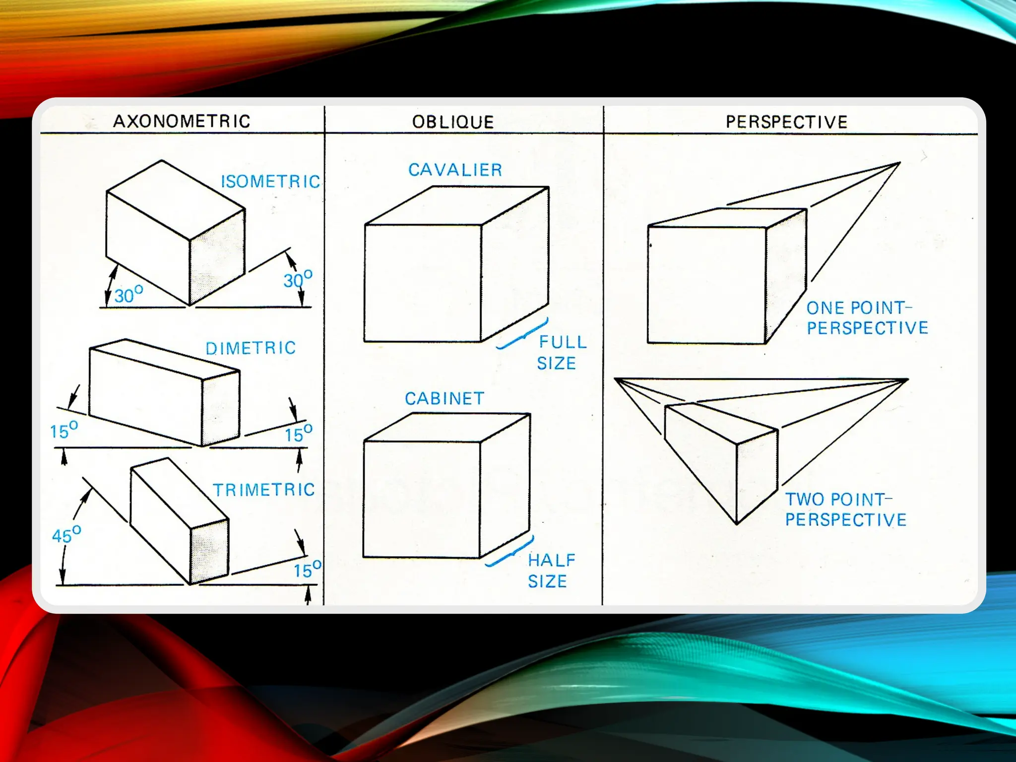
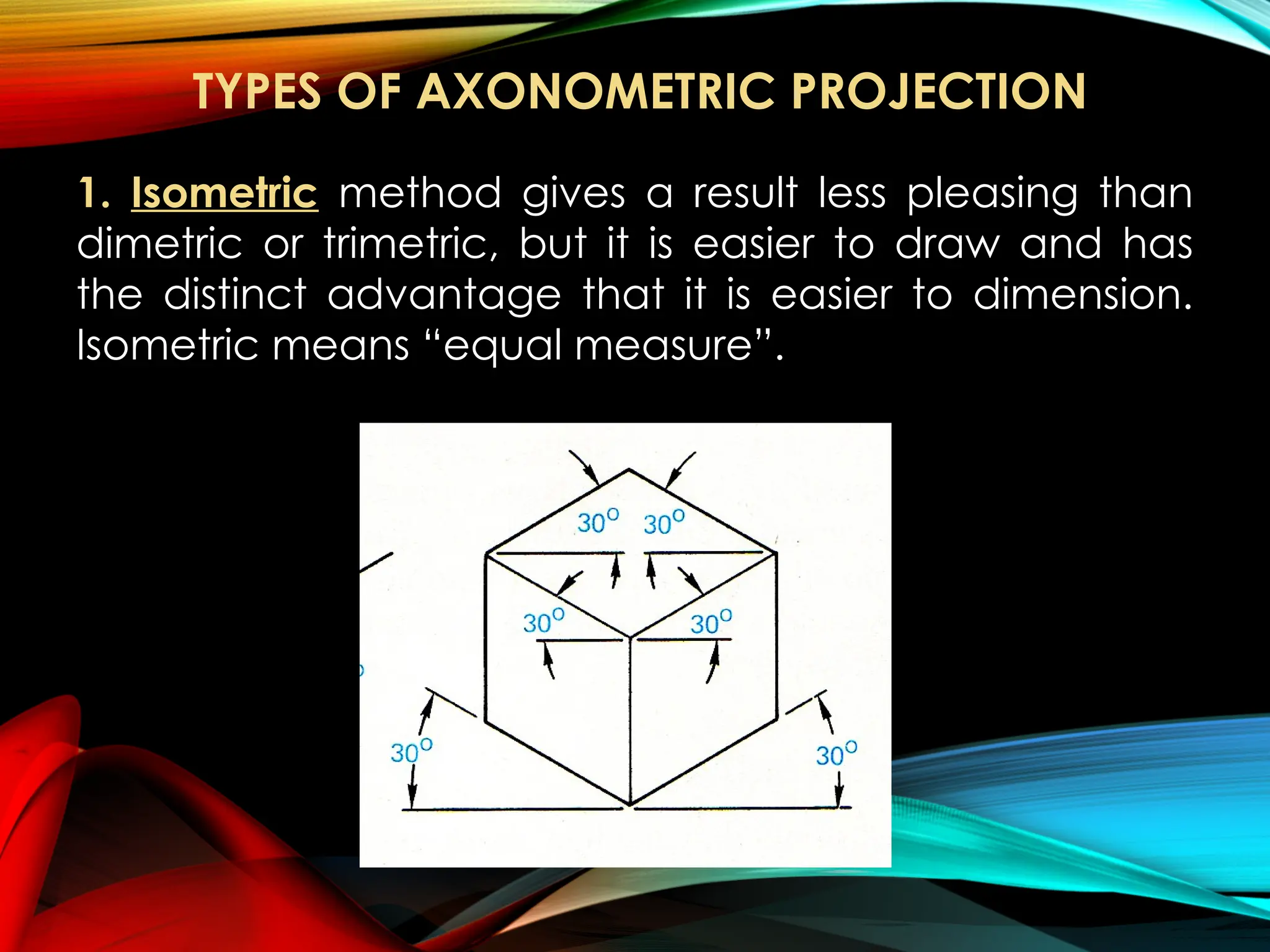
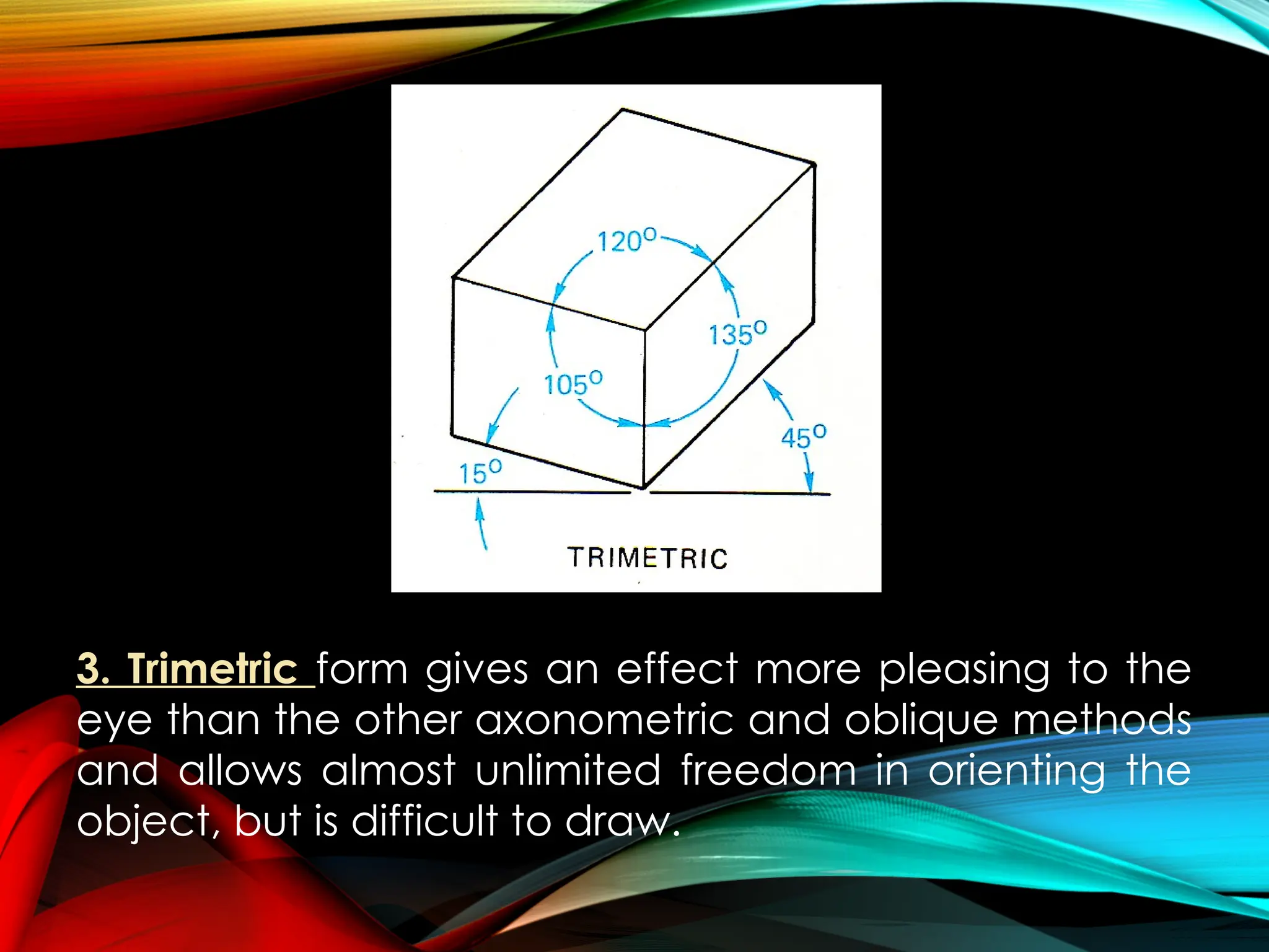
PICTORIAL
DRAWING
Prepared by:
REVILALYN E. FERNANDEZ
Instructor I
A single drawing that shows more
than one side of an object is called a
pictorial drawing.
Pictorial drawings are divided
into axonometric, oblique, and
perspective drawings.
Pictorial Drawing is a type of
drawing showing the three faces of an
object in a single drawing.
The most common pictorial drawings
used in the manufacturing industries are the
isometric, the oblique, and the perspective.
Of the three, the perspective is the most
pleasing to the eyes.
The fastest and most efficient pictorial
drawing is an isometric drawing.
1. Axonometric Projection – is theoretically
orthographic projection in which only one plane is
used, the object being turned so that three faces
show.
3 MAIN DIVISION OF PICTORIAL DRAWING
3. Perspective Drawing – is a method by which a
picture can be projected upon a picture plane in
much the same way as in photography.
2. Oblique Projection – When the projectors make
an angle other than 90° with the picture plane,
the resulting projection is called oblique.
TYPES OF AXONOMETRIC PROJECTION
1. Isometric method gives a result less pleasing than
dimetric or trimetric, but it is easier to draw and has
the distinct advantage that it is easier to dimension.
Isometric means “equal measure”.
2. Dimetric With the dimetric method, the result is less
pleasing and there is less freedom in orienting the
object, but execution is easier than with trimetric.
3. Trimetric form gives an effect more pleasing to the
eye than the other axonometric and oblique methods
and allows almost unlimited freedom in orienting the
object, but is difficult to draw.
ISOMETRIC
DRAWING
The term isometric is derived from two
words: iso, "equal," and metric, "measure." The
word isometric thus means "equal measure."
In other words, the size of an isometric
view is in equal measure either to its
orthographic views or to the scaled drawing.
It is generally in equal measure to the
size of the orthographic views. Hence, all
measurements used or laid out in an isometric
drawing are taken from orthographic views.
1
2 3
1.Vertical axes
2.30° left cross-axes
3.30° right cross-
axes
THREE AXES OF AN ISOMETRIC DRAWING
The three positions involved in drawing these axes
The axes in the first position are used when one
desires to build up the isometric view from the bottom
of the object. The second position is used when one
desires to construct the view from the top of the
object.
The isometric axes are very light lines and
are drawn before the visible lines or edges of
the object.
All measurements are laid parallel to or
along these axes.
In this figure a hollow block of wood is drawn in
orthographic views and its isometric view drawn at the
right side. It will be noted that the principal
measurements, namely, thickness (T), width (W), and
length (L), of the isometric drawing are made equal in
measure to those found in the orthographic views.
All edges of the object parallel to the
axes are called isometric lines and those not
parallel to them are called nonisometric lines.
The most widely used method of
drawing an isometric view is the "boxing"
method. In this method, a "box" is drawn with
its edges parallel to the isometric axes. These
edges, or lines, are drawn very lightly and
hence they are sometimes called crate lines
or construction lines.
Another method of drawing the isometric
view of an object, especially one with many
inclined surfaces, is the “offset” method.
In this figure, points 2 and 3 in the top view are first located on the
base of the isometric view by transferring distances 0-2 and 0-3 along
the cross-axes. From these points, isometric lines are drawn until they
intersect at point 4. From point 4 the altitude of the object (the distance
4-1) is measured to determine the vertex or point 1. The view is
completed by drawing visible lines from the corners of the base to this
vertex.
STEPS IN MAKING
ISOMETRIC DRAWING
1. Draw the three axes as light and straight as
possible. Be sure the cross-axes are about 30° from
the lower edge of the paper.
2. Lay out the principal measurements on the axes.
Get these measurements from the orthographic
views.
3. Draw the "box” or crate lines.
4. Draw the details of the object.
5. Check the accuracy of your drawing.
6. Trace the visible edges with heavier lines.
7. If required, show the hidden edges.
8. Label the isometric view.
Week 1-3 PICTORIAL Drawing_Division of Pictorial Drawing.pptx

Week 1-3 PICTORIAL Drawing_Division of Pictorial Drawing.pptx

  • 1.
  • 2.
    A single drawingthat shows more than one side of an object is called a pictorial drawing. Pictorial drawings are divided into axonometric, oblique, and perspective drawings. Pictorial Drawing is a type of drawing showing the three faces of an object in a single drawing.
  • 3.
    The most commonpictorial drawings used in the manufacturing industries are the isometric, the oblique, and the perspective. Of the three, the perspective is the most pleasing to the eyes. The fastest and most efficient pictorial drawing is an isometric drawing.
  • 4.
    1. Axonometric Projection– is theoretically orthographic projection in which only one plane is used, the object being turned so that three faces show. 3 MAIN DIVISION OF PICTORIAL DRAWING 3. Perspective Drawing – is a method by which a picture can be projected upon a picture plane in much the same way as in photography. 2. Oblique Projection – When the projectors make an angle other than 90° with the picture plane, the resulting projection is called oblique.
  • 6.
    TYPES OF AXONOMETRICPROJECTION 1. Isometric method gives a result less pleasing than dimetric or trimetric, but it is easier to draw and has the distinct advantage that it is easier to dimension. Isometric means “equal measure”.
  • 7.
    2. Dimetric Withthe dimetric method, the result is less pleasing and there is less freedom in orienting the object, but execution is easier than with trimetric.
  • 8.
    3. Trimetric formgives an effect more pleasing to the eye than the other axonometric and oblique methods and allows almost unlimited freedom in orienting the object, but is difficult to draw.
  • 9.
  • 10.
    The term isometricis derived from two words: iso, "equal," and metric, "measure." The word isometric thus means "equal measure." In other words, the size of an isometric view is in equal measure either to its orthographic views or to the scaled drawing. It is generally in equal measure to the size of the orthographic views. Hence, all measurements used or laid out in an isometric drawing are taken from orthographic views.
  • 11.
    1 2 3 1.Vertical axes 2.30°left cross-axes 3.30° right cross- axes THREE AXES OF AN ISOMETRIC DRAWING
  • 12.
    The three positionsinvolved in drawing these axes The axes in the first position are used when one desires to build up the isometric view from the bottom of the object. The second position is used when one desires to construct the view from the top of the object.
  • 13.
    The isometric axesare very light lines and are drawn before the visible lines or edges of the object. All measurements are laid parallel to or along these axes.
  • 14.
    In this figurea hollow block of wood is drawn in orthographic views and its isometric view drawn at the right side. It will be noted that the principal measurements, namely, thickness (T), width (W), and length (L), of the isometric drawing are made equal in measure to those found in the orthographic views.
  • 15.
    All edges ofthe object parallel to the axes are called isometric lines and those not parallel to them are called nonisometric lines.
  • 16.
    The most widelyused method of drawing an isometric view is the "boxing" method. In this method, a "box" is drawn with its edges parallel to the isometric axes. These edges, or lines, are drawn very lightly and hence they are sometimes called crate lines or construction lines. Another method of drawing the isometric view of an object, especially one with many inclined surfaces, is the “offset” method.
  • 17.
    In this figure,points 2 and 3 in the top view are first located on the base of the isometric view by transferring distances 0-2 and 0-3 along the cross-axes. From these points, isometric lines are drawn until they intersect at point 4. From point 4 the altitude of the object (the distance 4-1) is measured to determine the vertex or point 1. The view is completed by drawing visible lines from the corners of the base to this vertex.
  • 18.
  • 19.
    1. Draw thethree axes as light and straight as possible. Be sure the cross-axes are about 30° from the lower edge of the paper. 2. Lay out the principal measurements on the axes. Get these measurements from the orthographic views. 3. Draw the "box” or crate lines. 4. Draw the details of the object. 5. Check the accuracy of your drawing. 6. Trace the visible edges with heavier lines. 7. If required, show the hidden edges. 8. Label the isometric view.