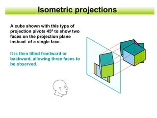
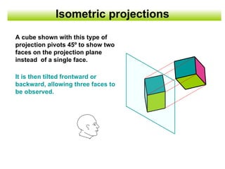
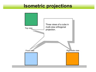
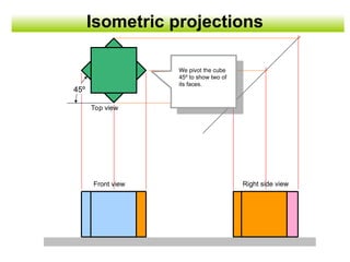
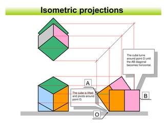
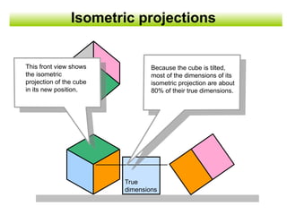
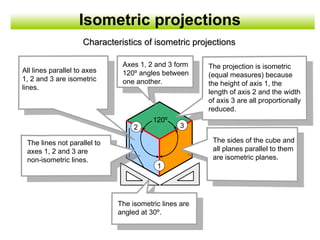
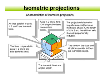
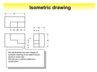
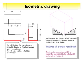
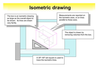
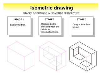
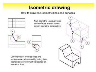
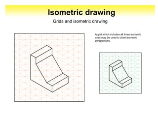
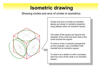
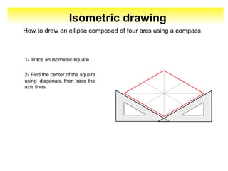
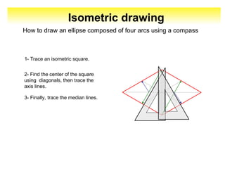
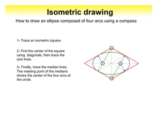
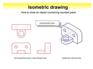
Isometric
drawings
(perspectives)
Working document
Linguistic review 29-09-07
Isometric projections
A cube shown with this type of
projection pivots 45º to show two
faces on the projection plane
instead of a single face.
It is then tilted frontward or
backward, allowing three faces to
be observed.
Isometric projections
A cube shown with this type of
projection pivots 45º to show two
faces on the projection plane
instead of a single face.
It is then tilted frontward or
backward, allowing three faces to
be observed.
Isometric projections
Three views of a cube in
multi-view orthogonal
projection.
Top view
Front view Right side view
Isometric projections
45º
We pivot the cube
45º to show two of
its faces.
Top view
Front view Right side view
The cube is lifted
and pivots around
point O.
Isometric projections
The cube turns
around point O until
the AB diagonal
becomes horizontal.
O
A
B
Isometric projections
This front view shows
the isometric
projection of the cube
in its new position.
True
dimensions
Because the cube is tilted,
most of the dimensions of its
isometric projection are about
80% of their true dimensions.
Isometric projections
This front view shows
the isometric
projection of the cube
in its new position.
True
dimensions
Because the cube is tilted,
most of the dimensions of its
isometric projection are about
80% of their true dimensions.
Isometric projections
All lines parallel to axes
1, 2 and 3 are isometric
lines.
2 3
1
120º
The isometric lines are
angled at 30º.
The lines not parallel to
axes 1, 2 and 3 are
non-isometric lines.
The sides of the cube and
all planes parallel to them
are isometric planes.
Axes 1, 2 and 3 form
120º angles between
one another.
The projection is isometric
(equal measures) because
the height of axis 1, the
length of axis 2 and the width
of axis 3 are all proportionally
reduced.
Characteristics of isometric projections
All lines parallel to axes
1, 2 and 3 are isometric
lines.
2 3
1
120º
The isometric lines are
angled at 30º.
The lines not parallel to
axes 1, 2 and 3 are
non-isometric lines.
The sides of the cube and
all planes parallel to them
are isometric planes.
Axes 1, 2 and 3 form
120º angles between
one another.
The projection is isometric
(equal measures) because
the height of axis 1, the length
of axis 2 and the width of axis
3 are all proportionally
reduced.
Characteristics of isometric projections
Isometric projections
Isometric drawing
20
20
50
10
8
14
28
35
We will illustrate the main stages of
isometric drawing of the object shown
above in multi-view.
We will use a method called box
construction.
20
20
50
10
8
14
28
35
We will illustrate the main stages of
isometric drawing of the object shown
above in multi-view.
We will use a method called box
construction.
To create the box, use construction lines to
outline an isometric box as large as the
overall object to be drawn.
The vertical axis is equal to the real height.
The two other axes, drawn at 30° to
horizontal, correspond to the actual width
and length of the object.
Isometric drawing
20
20
50
10
8
14
28
35
We will illustrate the main stages of
isometric drawing of the object shown
above in multi-view.
We will use a method called box
construction.
To create the box, use construction lines to
outline an isometric box as large as the
overall object to be drawn.
The vertical axis is equal to the real height.
The two other axes, drawn at 30° to
horizontal, correspond to the actual width
and length of the object.
Isometric drawing
Isometric drawing
The object is drawn by
removing volumes from the box.
A 30º- 60º set square is used to
trace the isometric lines.
The box is an isometric drawing
as large as the overall object to
be shown. Its lines are drawn
very faintly.
Measurements are reported on
the isometric axes, or on lines
parallel to these axes.
Isometric drawing
STAGE 1 STAGE 2 STAGE 3
Sketch the box.
STAGES OF DRAWING IN ISOMETRIC PERSPECTIVE
Measure on the
axes and trace the
details in
construction lines.
Carry out the final
layout.
Isometric drawing
STAGE 1 STAGE 2 STAGE 3
Sketch the box.
STAGES OF DRAWING IN ISOMETRIC PERSPECTIVE
Measure on the
axes and trace the
details in
construction lines.
Carry out the final
layout.
Non-isometric (oblique) lines
and surfaces are not true to
size in isometric perspective.
Isometric drawing
How to draw non-isometric lines and surfaces
Dimensions of inclined lines and
surfaces are determined by using their
coordinates which must be located on
isometric lines.
A
B
D
C
C
D
A
B
Isometric drawing
Non-isometric (oblique) lines
and surfaces are not true to
size in isometric perspective.
How to draw non-isometric lines and surfaces
Dimensions of inclined lines and
surfaces are determined by using their
coordinates which must be located on
isometric lines.
A
B
D
C
C
D
A
B
Isometric drawing
Grids and isometric drawing
A grid which includes all three isometric
axes may be used to draw isometric
perspectives.
Isometric drawing
Grids and isometric drawing
A grid which includes all three isometric
axes may be used to draw isometric
perspectives.
Isometric drawing
Showing circles and arcs of circles in isometrics
Circles and arcs of circles on isometric
planes are shown in isometric projection
using ellipses within an isometric square.
The sides of the square are equal to the
diameter of the circle and each side of the
circle touches the square.
To draw a circle in isometric perspective
on the computer, use a modified circle
inserted into an isometric square.
To draw it as a sketch or with a compass,
draw four arcs of the circle in an isometric
square.
Isometric drawing
How to draw an ellipse composed of four arcs using a compass
1- Trace an isometric square.
2- Find the center of the square
using diagonals, then trace the
axis lines.
Isometric drawing
How to draw an ellipse composed of four arcs using a compass
1- Trace an isometric square.
2- Find the center of the square
using diagonals, then trace the
axis lines.
3- Finally, trace the median lines.
Isometric drawing
How to draw an ellipse composed of four arcs using a compass
3- Finally, trace the median lines.
The meeting point of the medians
shows the center of the four arcs of
the circle.
1- Trace an isometric square.
2- Find the center of the square
using diagonals, then trace the
axis lines.
Isometric drawing
ORTHOGRAPHIC MULTI-VIEW PROJECTION ISOMETRIC PROJECTION
«Construction box»
How to draw an object containing rounded parts
STIRLING, Norman. « Éléments de dessin industriel », Montréal, HRW,
1979, 372 p.
JENSEN, C.H. « Dessin industriel », Montréal, McGraw-Hill, 1972, 752 p.
GIESECKE, Frederick E., MITCHELL, Alva, SPENCER, Henry Cecil, HILL,
Ivan Leroy, GYGDON, John Thomas et NGUYEN, Dinh N. « Dessin
technique », Montréal, Éditions du Renouveau Pédagogique inc., 1982, 769
p
Bibliography

engineering drawing isometric projection

  • 1.
  • 2.
    Isometric projections A cubeshown with this type of projection pivots 45º to show two faces on the projection plane instead of a single face. It is then tilted frontward or backward, allowing three faces to be observed.
  • 3.
    Isometric projections A cubeshown with this type of projection pivots 45º to show two faces on the projection plane instead of a single face. It is then tilted frontward or backward, allowing three faces to be observed.
  • 4.
    Isometric projections Three viewsof a cube in multi-view orthogonal projection. Top view Front view Right side view
  • 5.
    Isometric projections 45º We pivotthe cube 45º to show two of its faces. Top view Front view Right side view
  • 6.
    The cube islifted and pivots around point O. Isometric projections The cube turns around point O until the AB diagonal becomes horizontal. O A B
  • 7.
    Isometric projections This frontview shows the isometric projection of the cube in its new position. True dimensions Because the cube is tilted, most of the dimensions of its isometric projection are about 80% of their true dimensions.
  • 8.
    Isometric projections This frontview shows the isometric projection of the cube in its new position. True dimensions Because the cube is tilted, most of the dimensions of its isometric projection are about 80% of their true dimensions.
  • 9.
    Isometric projections All linesparallel to axes 1, 2 and 3 are isometric lines. 2 3 1 120º The isometric lines are angled at 30º. The lines not parallel to axes 1, 2 and 3 are non-isometric lines. The sides of the cube and all planes parallel to them are isometric planes. Axes 1, 2 and 3 form 120º angles between one another. The projection is isometric (equal measures) because the height of axis 1, the length of axis 2 and the width of axis 3 are all proportionally reduced. Characteristics of isometric projections Characteristics of isometric projections
  • 10.
    All lines parallelto axes 1, 2 and 3 are isometric lines. 2 3 1 120º The isometric lines are angled at 30º. The lines not parallel to axes 1, 2 and 3 are non-isometric lines. The sides of the cube and all planes parallel to them are isometric planes. Axes 1, 2 and 3 form 120º angles between one another. The projection is isometric (equal measures) because the height of axis 1, the length of axis 2 and the width of axis 3 are all proportionally reduced. Characteristics of isometric projections Characteristics of isometric projections Isometric projections
  • 11.
    Isometric drawing 20 20 50 10 8 14 28 35 We willillustrate the main stages of isometric drawing of the object shown above in multi-view. We will use a method called box construction.
  • 12.
    20 20 50 10 8 14 28 35 We will illustratethe main stages of isometric drawing of the object shown above in multi-view. We will use a method called box construction. To create the box, use construction lines to outline an isometric box as large as the overall object to be drawn. The vertical axis is equal to the real height. The two other axes, drawn at 30° to horizontal, correspond to the actual width and length of the object. Isometric drawing
  • 13.
    20 20 50 10 8 14 28 35 We will illustratethe main stages of isometric drawing of the object shown above in multi-view. We will use a method called box construction. To create the box, use construction lines to outline an isometric box as large as the overall object to be drawn. The vertical axis is equal to the real height. The two other axes, drawn at 30° to horizontal, correspond to the actual width and length of the object. Isometric drawing
  • 14.
    Isometric drawing The objectis drawn by removing volumes from the box. A 30º- 60º set square is used to trace the isometric lines. The box is an isometric drawing as large as the overall object to be shown. Its lines are drawn very faintly. Measurements are reported on the isometric axes, or on lines parallel to these axes.
  • 15.
    Isometric drawing The objectis drawn by removing volumes from the box. A 30º- 60º set square is used to trace the isometric lines. The box is an isometric drawing as large as the overall object to be shown. Its lines are drawn very faintly. Measurements are reported on the isometric axes, or on lines parallel to these axes.
  • 16.
    Isometric drawing STAGE 1STAGE 2 STAGE 3 Sketch the box. STAGES OF DRAWING IN ISOMETRIC PERSPECTIVE Measure on the axes and trace the details in construction lines. Carry out the final layout.
  • 17.
    Isometric drawing STAGE 1STAGE 2 STAGE 3 Sketch the box. STAGES OF DRAWING IN ISOMETRIC PERSPECTIVE Measure on the axes and trace the details in construction lines. Carry out the final layout.
  • 18.
    Non-isometric (oblique) lines andsurfaces are not true to size in isometric perspective. Isometric drawing How to draw non-isometric lines and surfaces Dimensions of inclined lines and surfaces are determined by using their coordinates which must be located on isometric lines. A B D C C D A B
  • 19.
    Isometric drawing Non-isometric (oblique)lines and surfaces are not true to size in isometric perspective. How to draw non-isometric lines and surfaces Dimensions of inclined lines and surfaces are determined by using their coordinates which must be located on isometric lines. A B D C C D A B
  • 20.
    Isometric drawing Grids andisometric drawing A grid which includes all three isometric axes may be used to draw isometric perspectives.
  • 21.
    Isometric drawing Grids andisometric drawing A grid which includes all three isometric axes may be used to draw isometric perspectives.
  • 22.
    Isometric drawing Showing circlesand arcs of circles in isometrics Circles and arcs of circles on isometric planes are shown in isometric projection using ellipses within an isometric square. The sides of the square are equal to the diameter of the circle and each side of the circle touches the square. To draw a circle in isometric perspective on the computer, use a modified circle inserted into an isometric square. To draw it as a sketch or with a compass, draw four arcs of the circle in an isometric square.
  • 23.
    Isometric drawing How todraw an ellipse composed of four arcs using a compass 1- Trace an isometric square. 2- Find the center of the square using diagonals, then trace the axis lines.
  • 24.
    Isometric drawing How todraw an ellipse composed of four arcs using a compass 1- Trace an isometric square. 2- Find the center of the square using diagonals, then trace the axis lines. 3- Finally, trace the median lines.
  • 25.
    Isometric drawing How todraw an ellipse composed of four arcs using a compass 3- Finally, trace the median lines. The meeting point of the medians shows the center of the four arcs of the circle. 1- Trace an isometric square. 2- Find the center of the square using diagonals, then trace the axis lines.
  • 26.
    Isometric drawing ORTHOGRAPHIC MULTI-VIEWPROJECTION ISOMETRIC PROJECTION «Construction box» How to draw an object containing rounded parts
  • 27.
    STIRLING, Norman. «Éléments de dessin industriel », Montréal, HRW, 1979, 372 p. JENSEN, C.H. « Dessin industriel », Montréal, McGraw-Hill, 1972, 752 p. GIESECKE, Frederick E., MITCHELL, Alva, SPENCER, Henry Cecil, HILL, Ivan Leroy, GYGDON, John Thomas et NGUYEN, Dinh N. « Dessin technique », Montréal, Éditions du Renouveau Pédagogique inc., 1982, 769 p Bibliography