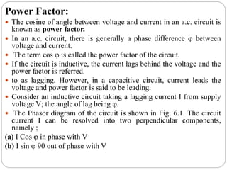
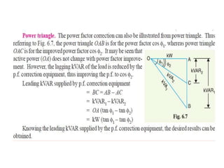
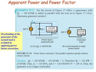
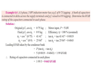
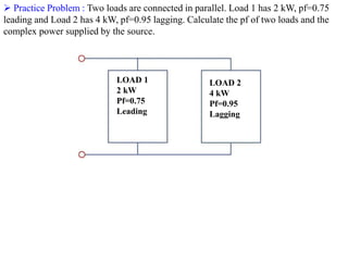
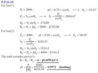
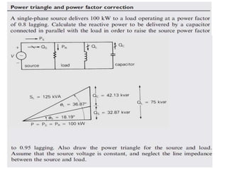
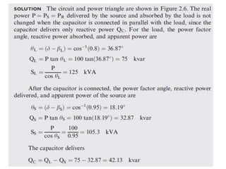
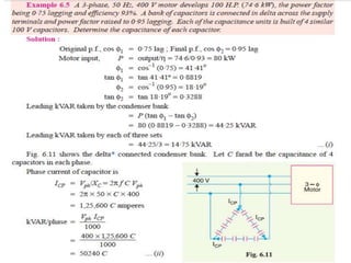
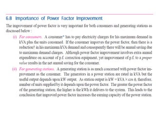
• Name : Engr. Muddasar Ali
Lecturer-EE
• Office : Male Faculty Office, Cabin # 11, WEC
• Education
MS-EE (Power Systems) : U.E.T- Taxila
(2015-17)
BEE (Power Systems): Air University, Islamabad .
. (2011-15)
• Belongs : Rawalpindi.
Instructor
Chapter 6
Power Factor Improvement
BY
BALA
KRISHNA
• The electrical energy is almost exclusively generated,
transmitted and distributed in the form of alternating current.
Therefore, the question of power factor immediately comes
into picture.
• Most of the loads (e.g. induction motors, arc lamps) are
inductive in nature and hence have low lagging power factor.
• The low power factor is highly undesirable as it causes an
increase in current, resulting in additional losses of active
power in all the elements of power system from power
station generator down to the utilization devices.
• In order to ensure most favorable conditions for a supply
system from engineering , it is important to have power
factor as close to unity as possible.
Power Factor:
 The cosine of angle between voltage and current in an a.c. circuit is
known as power factor.
 In an a.c. circuit, there is generally a phase difference φ between
voltage and current.
 The term cos φ is called the power factor of the circuit.
 If the circuit is inductive, the current lags behind the voltage and the
power factor is referred.
 to as lagging. However, in a capacitive circuit, current leads the
voltage and power factor is said to be leading.
 Consider an inductive circuit taking a lagging current I from supply
voltage V; the angle of lag being φ.
 The Phasor diagram of the circuit is shown in Fig. 6.1. The circuit
current I can be resolved into two perpendicular components,
namely ;
(a) I Cos φ in phase with V
(b) I sin φ 90 out of phase with V
 The component I cos φ is known as active or wattful
component, whereas component I sin φ is called the reactive or
wattless component.
 The reactive component is a measure of the power factor.
 If the reactive component is small, the phase angle φ is small
and hence power factor cos φ will be high.
 Therefore, a circuit having small reactive current (i.e., I sin φ)
will have high power factor and vice-versa. It may be noted
that value of power factor can never be more than unity.
 It is a usual practice to attach the word ‘lagging’ or ‘leading’
with the numerical value of power factor to signify whether the
current lags or leads the voltage.
 Thus if the circuit has a p.f. of 0·5 and the current lags the
voltage, we generally write p.f. as 0·5 lagging.
 Sometimes power factor is expressed as a percentage. Thus 0·8
lagging power factor may be expressed as 80% lagging.
Apparent Power and Power Factor
Overloading of the
generator of the
second load is
avoided by
applying power
factor correction.
 Practice Problem : Two loads are connected in parallel. Load 1 has 2 kW, pf=0.75
leading and Load 2 has 4 kW, pf=0.95 lagging. Calculate the pf of two loads and the
complex power supplied by the source.
LOAD 1
2 kW
Pf=0.75
Leading
LOAD 2
4 kW
Pf=0.95
Lagging
• For Practice Solve Course Book Examples
& Tutorial Problems.
Quiz # 4
• Quiz will be in Next Class.
• There will be no retake of this quiz.
• There will be 4 quizzes only and all the
quizzes will be included.
• Bring A4 Paper and calculator with you, no
exchange will be allowed.

Chapter 06_Pdu.pptx

  • 1.
    • Name :Engr. Muddasar Ali Lecturer-EE • Office : Male Faculty Office, Cabin # 11, WEC • Education MS-EE (Power Systems) : U.E.T- Taxila (2015-17) BEE (Power Systems): Air University, Islamabad . . (2011-15) • Belongs : Rawalpindi. Instructor
  • 2.
    Chapter 6 Power FactorImprovement BY BALA KRISHNA
  • 3.
    • The electricalenergy is almost exclusively generated, transmitted and distributed in the form of alternating current. Therefore, the question of power factor immediately comes into picture. • Most of the loads (e.g. induction motors, arc lamps) are inductive in nature and hence have low lagging power factor. • The low power factor is highly undesirable as it causes an increase in current, resulting in additional losses of active power in all the elements of power system from power station generator down to the utilization devices. • In order to ensure most favorable conditions for a supply system from engineering , it is important to have power factor as close to unity as possible.
  • 4.
    Power Factor:  Thecosine of angle between voltage and current in an a.c. circuit is known as power factor.  In an a.c. circuit, there is generally a phase difference φ between voltage and current.  The term cos φ is called the power factor of the circuit.  If the circuit is inductive, the current lags behind the voltage and the power factor is referred.  to as lagging. However, in a capacitive circuit, current leads the voltage and power factor is said to be leading.  Consider an inductive circuit taking a lagging current I from supply voltage V; the angle of lag being φ.  The Phasor diagram of the circuit is shown in Fig. 6.1. The circuit current I can be resolved into two perpendicular components, namely ; (a) I Cos φ in phase with V (b) I sin φ 90 out of phase with V
  • 6.
     The componentI cos φ is known as active or wattful component, whereas component I sin φ is called the reactive or wattless component.  The reactive component is a measure of the power factor.  If the reactive component is small, the phase angle φ is small and hence power factor cos φ will be high.  Therefore, a circuit having small reactive current (i.e., I sin φ) will have high power factor and vice-versa. It may be noted that value of power factor can never be more than unity.  It is a usual practice to attach the word ‘lagging’ or ‘leading’ with the numerical value of power factor to signify whether the current lags or leads the voltage.  Thus if the circuit has a p.f. of 0·5 and the current lags the voltage, we generally write p.f. as 0·5 lagging.  Sometimes power factor is expressed as a percentage. Thus 0·8 lagging power factor may be expressed as 80% lagging.
  • 18.
    Apparent Power andPower Factor Overloading of the generator of the second load is avoided by applying power factor correction.
  • 20.
     Practice Problem: Two loads are connected in parallel. Load 1 has 2 kW, pf=0.75 leading and Load 2 has 4 kW, pf=0.95 lagging. Calculate the pf of two loads and the complex power supplied by the source. LOAD 1 2 kW Pf=0.75 Leading LOAD 2 4 kW Pf=0.95 Lagging
  • 33.
    • For PracticeSolve Course Book Examples & Tutorial Problems.
  • 34.
    Quiz # 4 •Quiz will be in Next Class. • There will be no retake of this quiz. • There will be 4 quizzes only and all the quizzes will be included. • Bring A4 Paper and calculator with you, no exchange will be allowed.