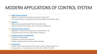
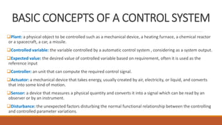
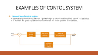
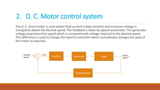
INTODUCTION TO
CONTROL SYSTEM
NAME: JAIMIN A. KEMKAR
EN. NO.: 160123119014
CLASS AND BATCH: 5TH D2
SUBJECT: CONTROL ENGINEERING
SUBJECT GUIDE: PROF. M. B. KHATRI
CONTENTS
Introduction to control system
Classification of systems
Examples of control systems
INTRODUCTION
What is control system?
◦ System: An interconnection of elements and devices for a desired purpose and/or objective.
◦ Control system: An interconnection of components forming a system configuration that will
provide a desired response.
◦ Process: The device, plant, or system under control. The input and output relationship
represents the cause-and-effect relationship of the process.
INPUT PROCESS OUTPUT
MODERN APPLICATIONS OF CONTROL SYSTEM
 Flight Control Systems
 Modern commercial and military aircraft are “fly by wire”
 Auto-land systems, unmanned aerial vehicles (UAVs) are already in place
 Robotics
 High accuracy positioning for flexible manufacturing
 Remote environments: space, sea, non-invasive surgery, etc.
 Chemical Process Control
 Regulation of flow rates, temperature, concentrations, etc.
 Long time scales, but only crude models of process
 Communications and Networks
 Amplifiers and repeaters
 Congestion control of the Internet
 Power management for wireless communications
 Automotive
 Engine control, transmission control, cruise control, climate control, etc.
 Luxury sedans: 12 control devices in 1976, 42 in 1988, 67 in 1991
BASIC CONCEPTS OF A CONTROL SYSTEM
Plant: a physical object to be controlled such as a mechanical device, a heating furnace, a chemical reactor
or a spacecraft, a car, a missile.
Controlled variable: the variable controlled by a automatic control system , considering as a system output.
Expected value: the desired value of controlled variable based on requirement, often it is used as the
reference input
Controller: an unit that can compute the required control signal.
Actuator: a mechanical device that takes energy, usually created by air, electricity, or liquid, and converts
that into some kind of motion.
Sensor: a device that measures a physical quantity and converts it into a signal which can be read by an
observer or by an instrument.
Disturbance: the unexpected factors disturbing the normal functional relationship between the controlling
and controlled parameter variations.
CLASSIFICATION OF CONTROL SYSTEM
Broadly control systems can be classified as,
1. Natural control system
◦ The biological system, systems inside human being are of natural type.
2. Man-made control system
◦ Vehicles, switches are the examples of the man-made controller.
3. Combinational control system
◦ Example like driver driving a vehicle.
4. Time varying and time invariant system
◦ Time varying control systems are those in which parameters of the system are varying with time. (fig. 1)
◦ It is not dependent on weather input and output are functions of time or not. (fig. 2)
Parameters of
system are
constant and not
functions of time
Parameters of
system are
functions of time
Classification
5. Linear and non linear system
I. A control system is said to be linear if it satisfies following properties
a) The principle of super position: this means the response to several inputs can be obtained by considering one input at a time
and then algebraically adding the individual results.
b) The differential equation describing the system is linear having its co-efficient as constants.
c) Practically the output i.e., response varies linearly with the input i.e., forcing function for linear system.
II. A control system said to be non-linear if it satisfies following properties
a) It does not satisfy the principle of superposition.
b) The equation describing the system are non-linear in nature.
EXAMPLES OF CONTOL SYSTEM
1. Manual Speed control system:
A locomotive operator driving a train is a good example of a manual speed control system. The objective
is to maintain the speed equal to the speed limits set. The entire system is shown bellow,
Control
action
(brain)
Actuators
(hands)
Vehicle
mechanism
Sensor
(eyes)
Speed
Limit
Actual
speed
+
-
The D. C. shunt motor is used where field current is kept constant and armature voltage is
changed to obtain the desired speed. The feedback is taken by speed tachometer. This generates
voltage proportional to speed which is compared with voltage required to the desired speed.
This difference is used to change the input to controller which cumulatively changes the sped of
the motor as required.
Amplifier Armature Load
Techometer
Desired
Speed
Actual
speed
+
-
Error
2. D. C. Motor control system
3. Home Heating System
In this system, the heating system is operated by a value. The actual temperature is sensed by a
thermal sensor and compared with the desired temperature. The difference between the two,
actuates the value mechanism to change the temperature as per requirement.
Value
Heating
system
Temperature
sensor
Desired
Temperature
House
temperature
+
-
Error
4. Temperature Control System
The aim is to dry clothes through heating. Clothes are placed and the system is providing heat
with the help of electrical energy. The heating element is attached and the sensors are used as
feedback devices. Sensors will change the value of heating according to its requirement.
Heating
eliment
clothes
sensor
Desired
dryness
Actual
dryness
+
-
Electrical
energy
Heat
referances
1. Books:
1. Booksindia
2. Technical publication
Intoduction to control system

Intoduction to control system

  • 1.
    INTODUCTION TO CONTROL SYSTEM NAME:JAIMIN A. KEMKAR EN. NO.: 160123119014 CLASS AND BATCH: 5TH D2 SUBJECT: CONTROL ENGINEERING SUBJECT GUIDE: PROF. M. B. KHATRI
  • 2.
    CONTENTS Introduction to controlsystem Classification of systems Examples of control systems
  • 3.
    INTRODUCTION What is controlsystem? ◦ System: An interconnection of elements and devices for a desired purpose and/or objective. ◦ Control system: An interconnection of components forming a system configuration that will provide a desired response. ◦ Process: The device, plant, or system under control. The input and output relationship represents the cause-and-effect relationship of the process. INPUT PROCESS OUTPUT
  • 4.
    MODERN APPLICATIONS OFCONTROL SYSTEM  Flight Control Systems  Modern commercial and military aircraft are “fly by wire”  Auto-land systems, unmanned aerial vehicles (UAVs) are already in place  Robotics  High accuracy positioning for flexible manufacturing  Remote environments: space, sea, non-invasive surgery, etc.  Chemical Process Control  Regulation of flow rates, temperature, concentrations, etc.  Long time scales, but only crude models of process  Communications and Networks  Amplifiers and repeaters  Congestion control of the Internet  Power management for wireless communications  Automotive  Engine control, transmission control, cruise control, climate control, etc.  Luxury sedans: 12 control devices in 1976, 42 in 1988, 67 in 1991
  • 5.
    BASIC CONCEPTS OFA CONTROL SYSTEM Plant: a physical object to be controlled such as a mechanical device, a heating furnace, a chemical reactor or a spacecraft, a car, a missile. Controlled variable: the variable controlled by a automatic control system , considering as a system output. Expected value: the desired value of controlled variable based on requirement, often it is used as the reference input Controller: an unit that can compute the required control signal. Actuator: a mechanical device that takes energy, usually created by air, electricity, or liquid, and converts that into some kind of motion. Sensor: a device that measures a physical quantity and converts it into a signal which can be read by an observer or by an instrument. Disturbance: the unexpected factors disturbing the normal functional relationship between the controlling and controlled parameter variations.
  • 6.
    CLASSIFICATION OF CONTROLSYSTEM Broadly control systems can be classified as, 1. Natural control system ◦ The biological system, systems inside human being are of natural type. 2. Man-made control system ◦ Vehicles, switches are the examples of the man-made controller. 3. Combinational control system ◦ Example like driver driving a vehicle. 4. Time varying and time invariant system ◦ Time varying control systems are those in which parameters of the system are varying with time. (fig. 1) ◦ It is not dependent on weather input and output are functions of time or not. (fig. 2) Parameters of system are constant and not functions of time Parameters of system are functions of time
  • 7.
    Classification 5. Linear andnon linear system I. A control system is said to be linear if it satisfies following properties a) The principle of super position: this means the response to several inputs can be obtained by considering one input at a time and then algebraically adding the individual results. b) The differential equation describing the system is linear having its co-efficient as constants. c) Practically the output i.e., response varies linearly with the input i.e., forcing function for linear system. II. A control system said to be non-linear if it satisfies following properties a) It does not satisfy the principle of superposition. b) The equation describing the system are non-linear in nature.
  • 8.
    EXAMPLES OF CONTOLSYSTEM 1. Manual Speed control system: A locomotive operator driving a train is a good example of a manual speed control system. The objective is to maintain the speed equal to the speed limits set. The entire system is shown bellow, Control action (brain) Actuators (hands) Vehicle mechanism Sensor (eyes) Speed Limit Actual speed + -
  • 9.
    The D. C.shunt motor is used where field current is kept constant and armature voltage is changed to obtain the desired speed. The feedback is taken by speed tachometer. This generates voltage proportional to speed which is compared with voltage required to the desired speed. This difference is used to change the input to controller which cumulatively changes the sped of the motor as required. Amplifier Armature Load Techometer Desired Speed Actual speed + - Error 2. D. C. Motor control system
  • 10.
    3. Home HeatingSystem In this system, the heating system is operated by a value. The actual temperature is sensed by a thermal sensor and compared with the desired temperature. The difference between the two, actuates the value mechanism to change the temperature as per requirement. Value Heating system Temperature sensor Desired Temperature House temperature + - Error
  • 11.
    4. Temperature ControlSystem The aim is to dry clothes through heating. Clothes are placed and the system is providing heat with the help of electrical energy. The heating element is attached and the sensors are used as feedback devices. Sensors will change the value of heating according to its requirement. Heating eliment clothes sensor Desired dryness Actual dryness + - Electrical energy Heat
  • 12.