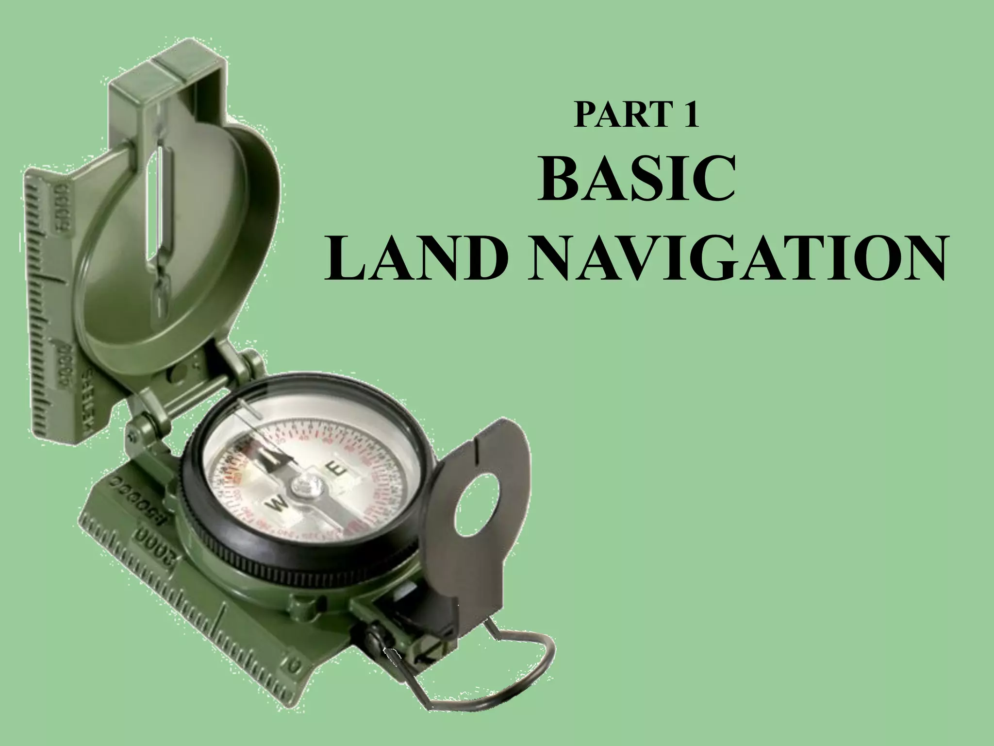
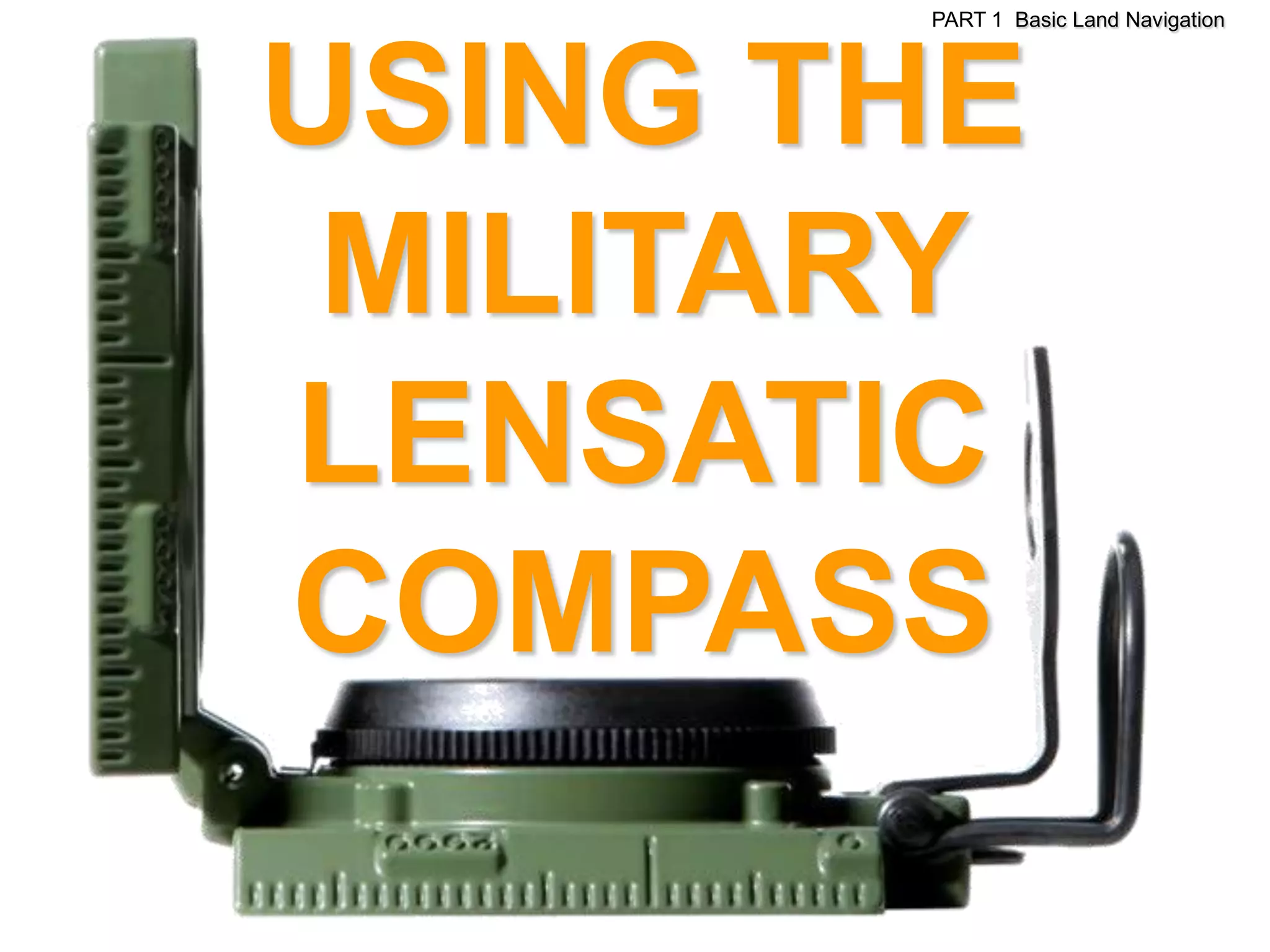
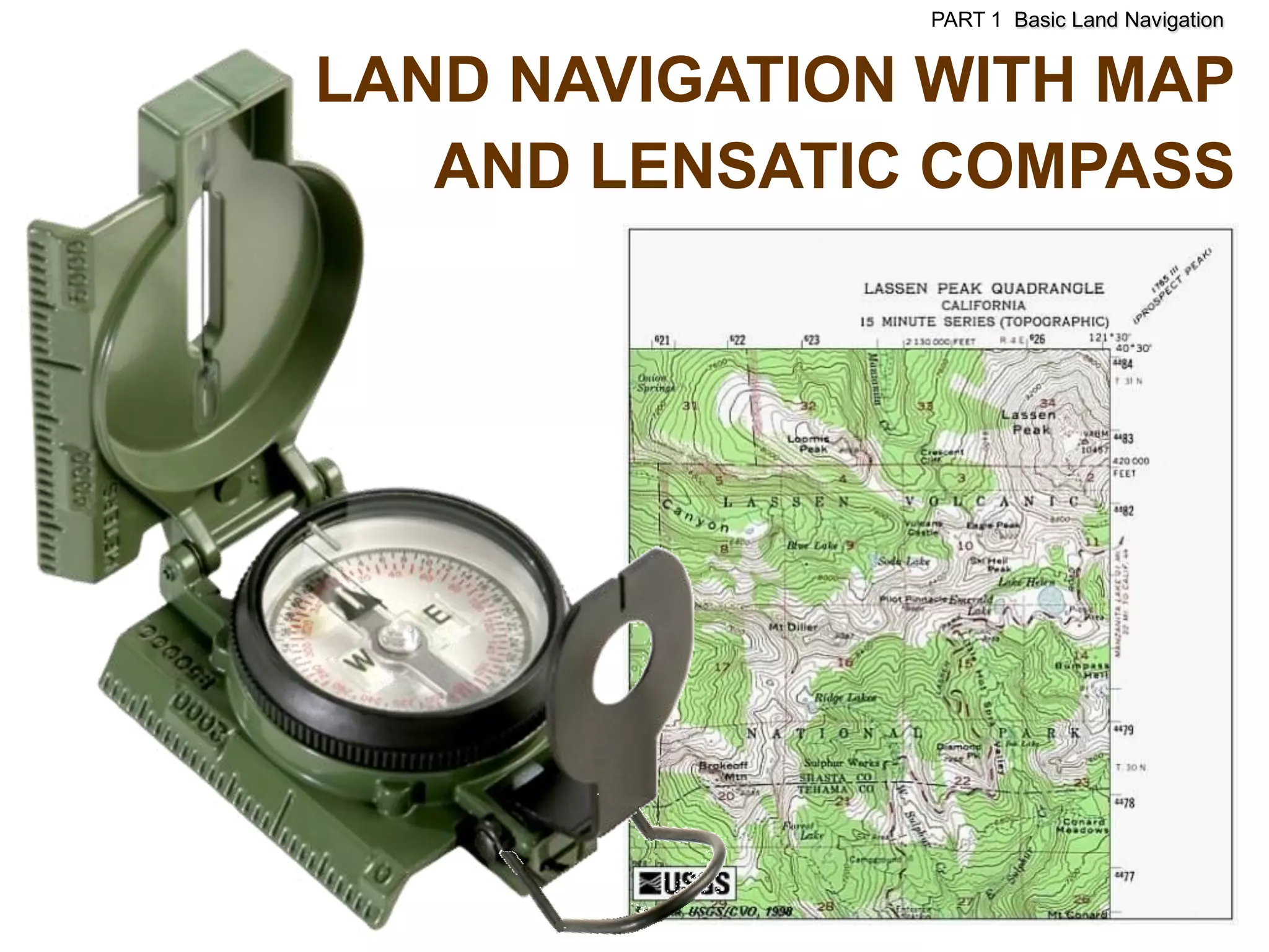
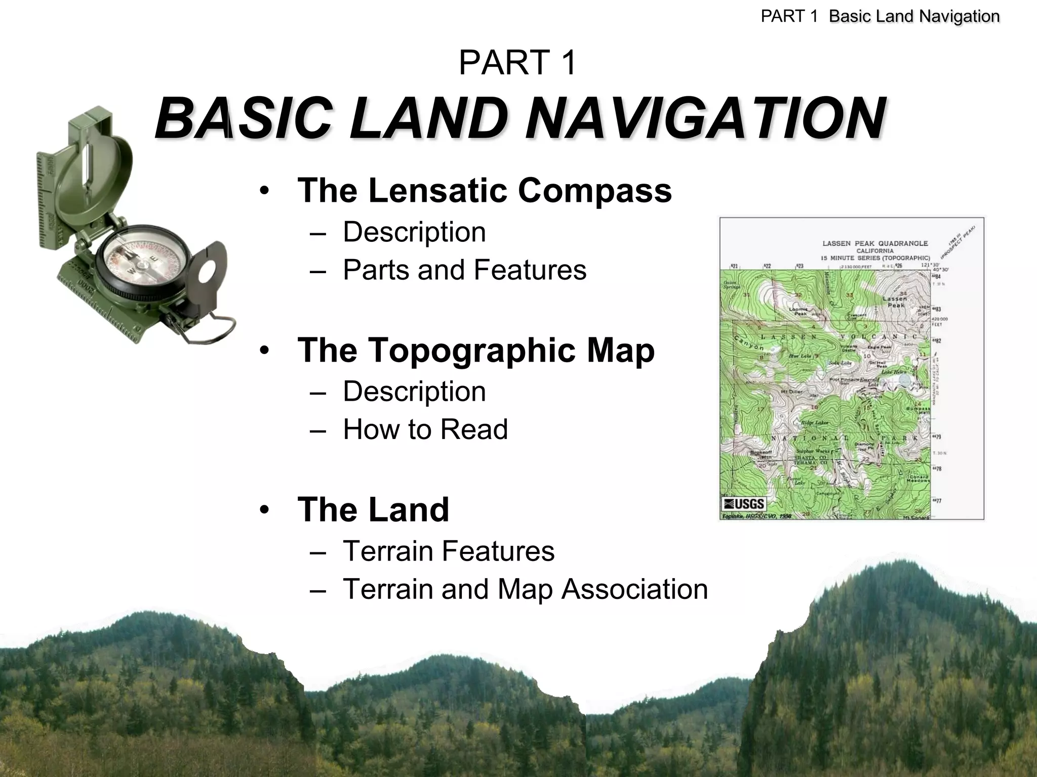
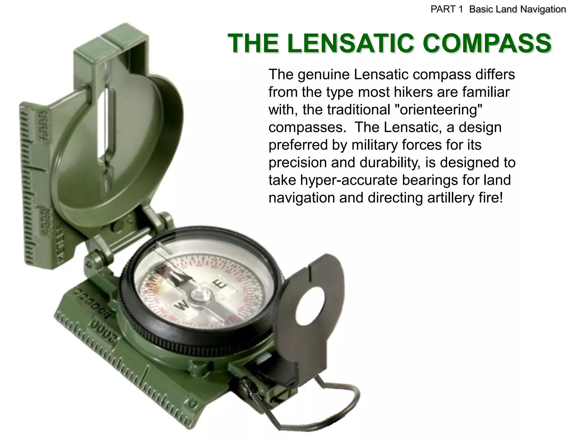
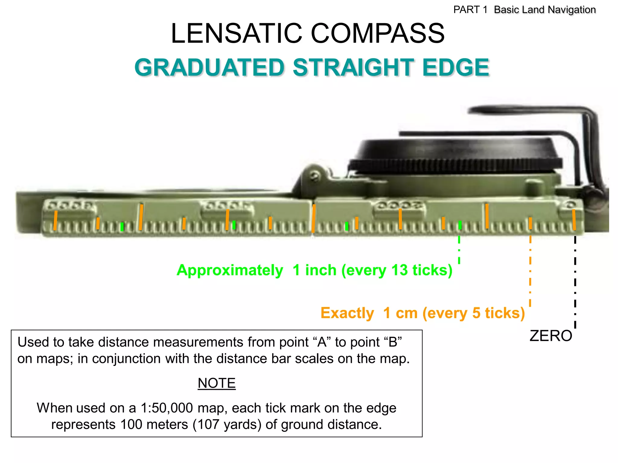
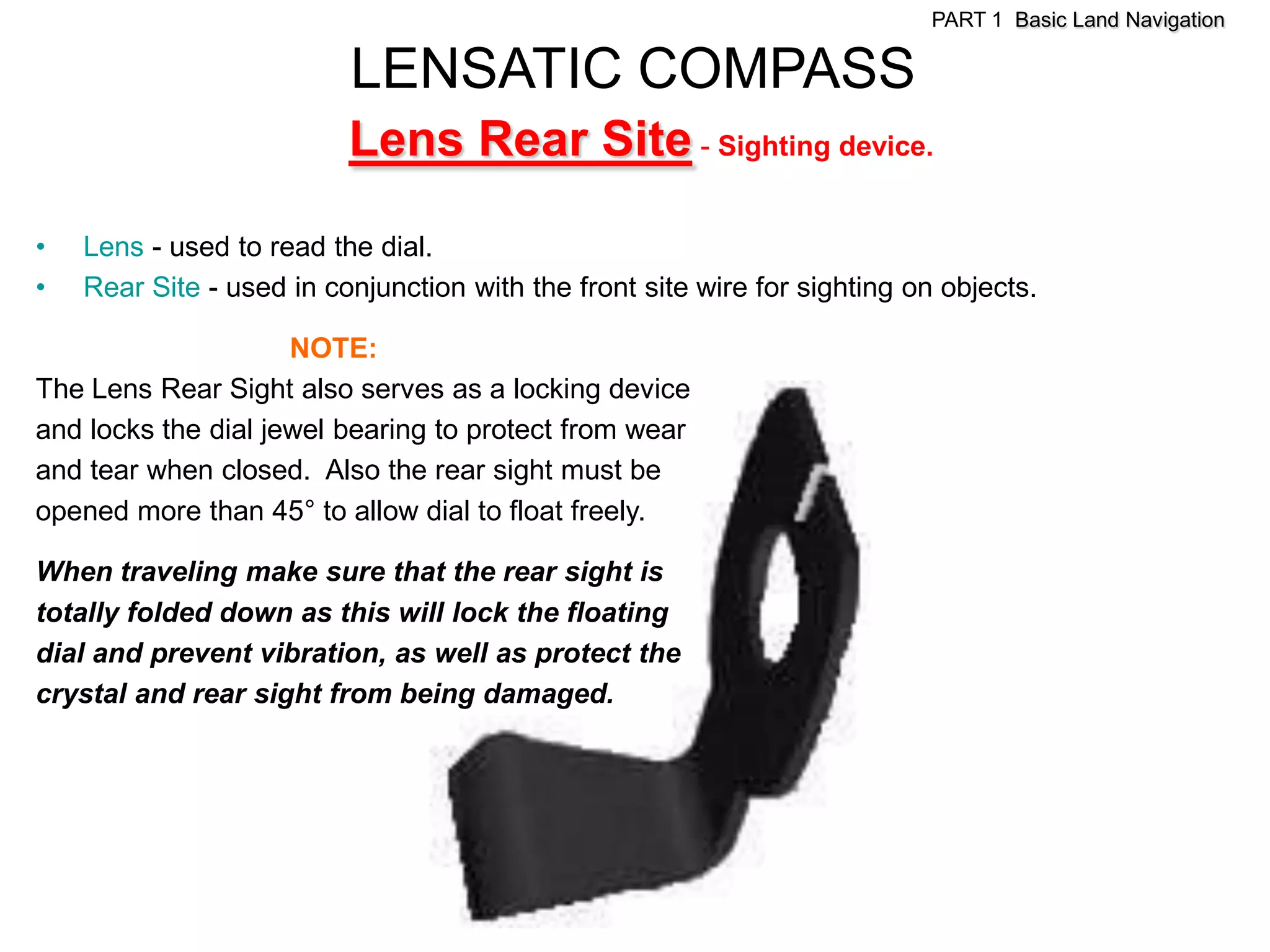
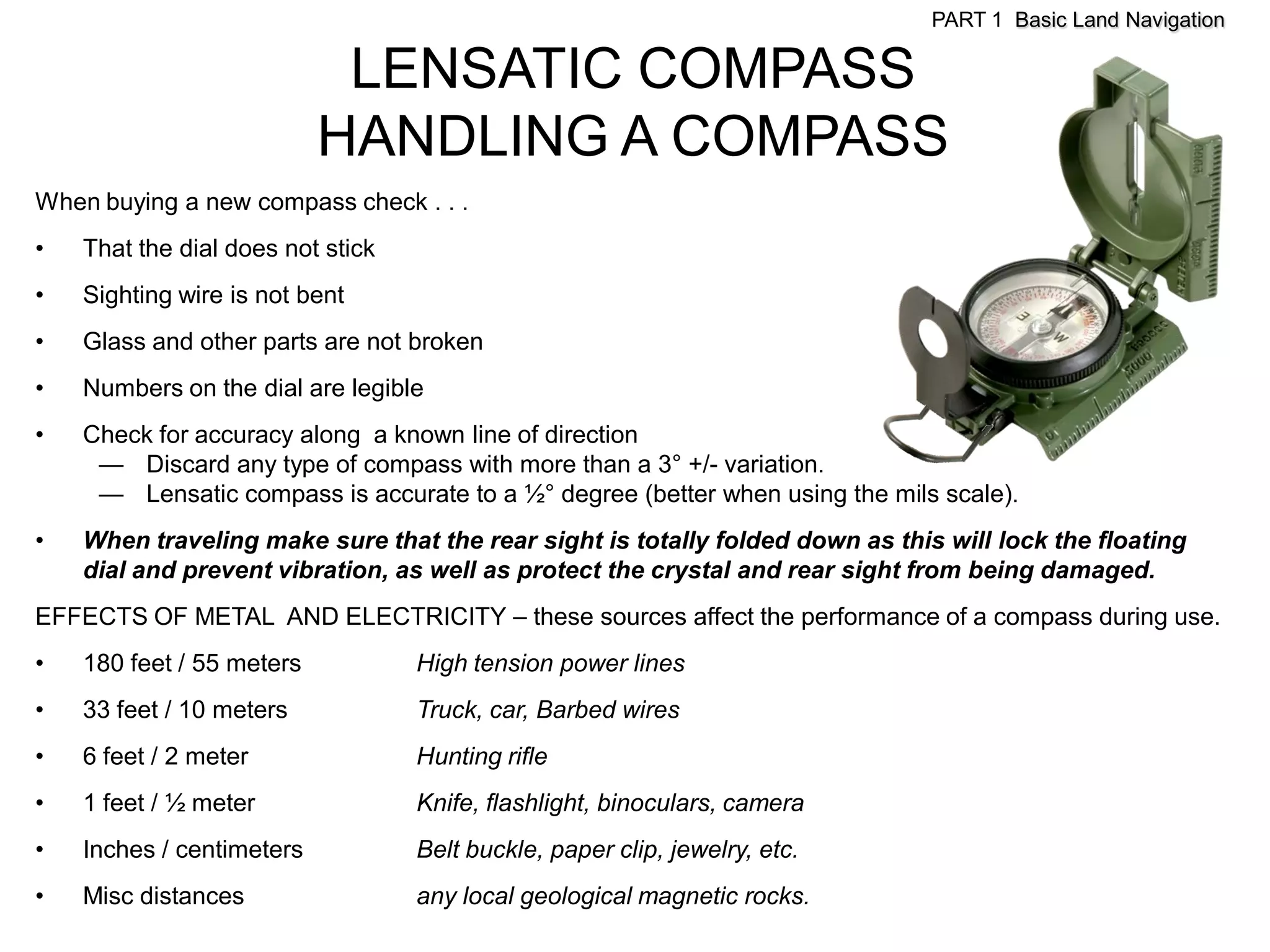
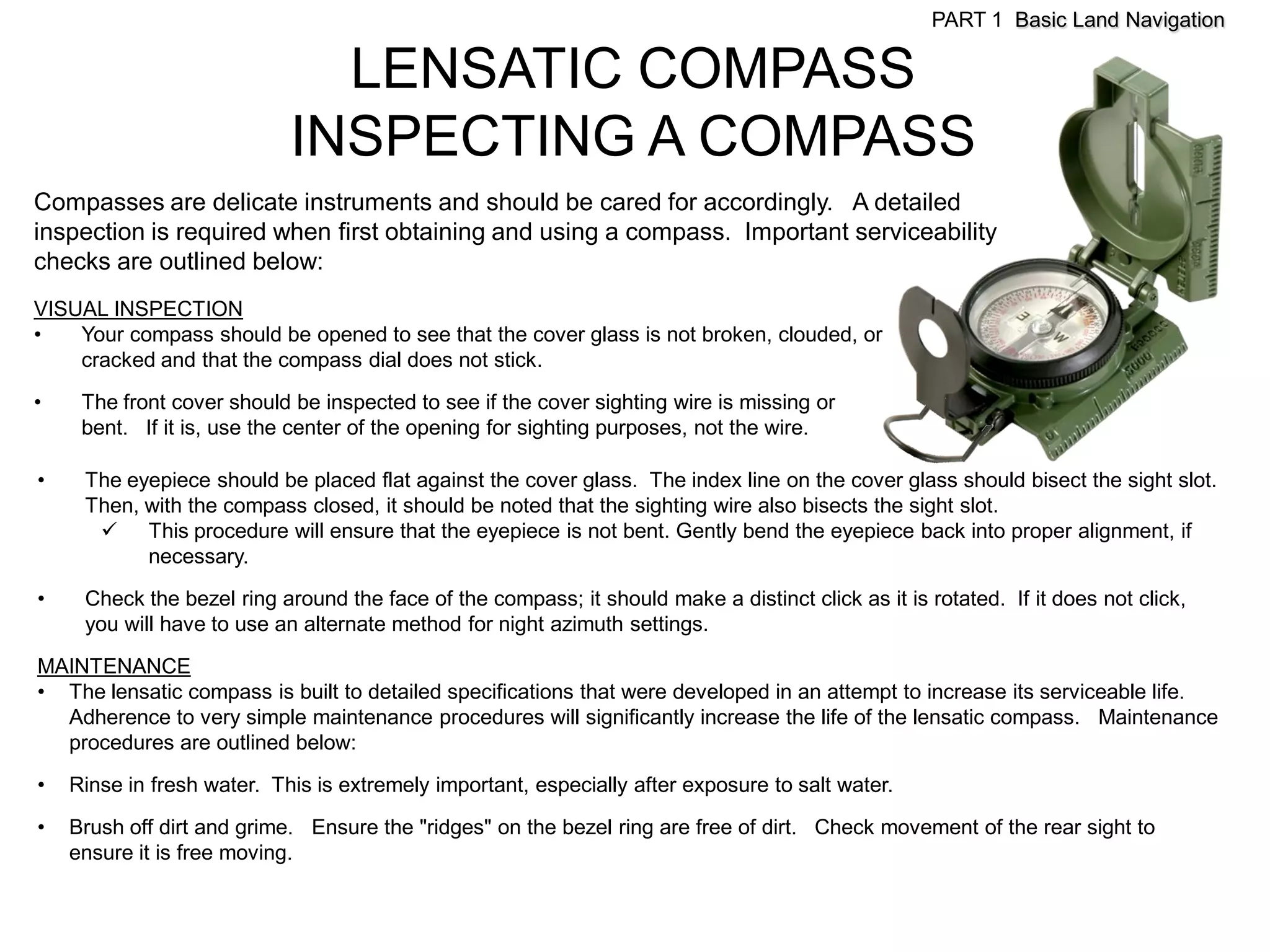
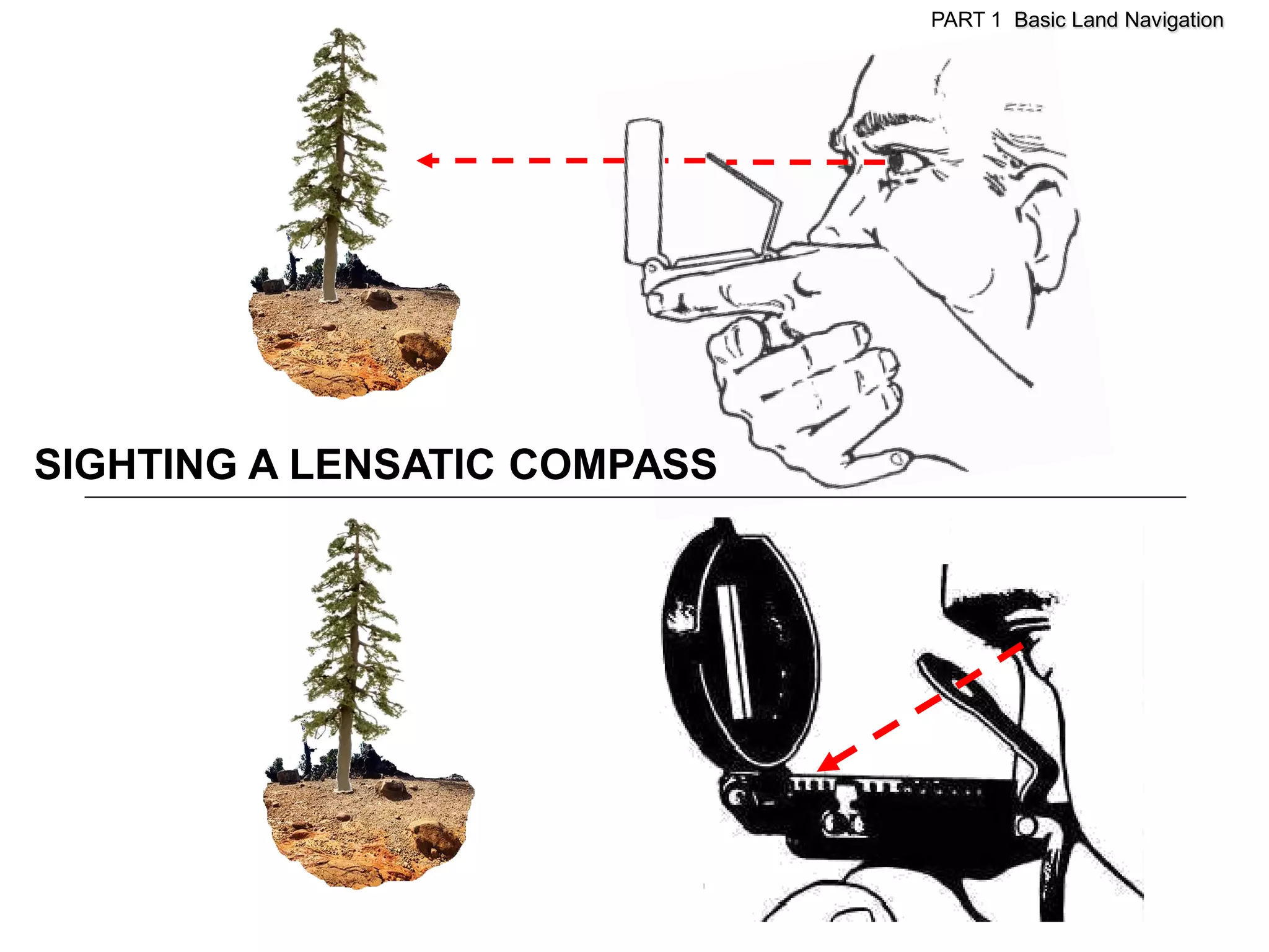
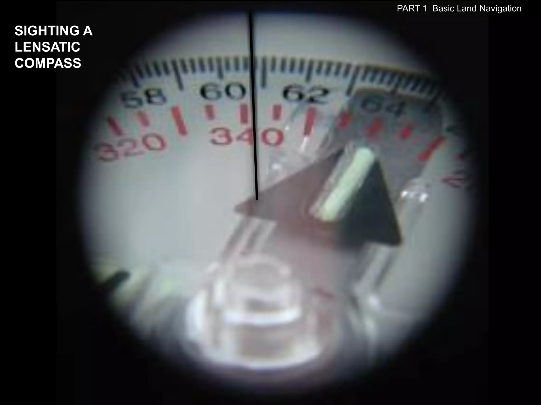
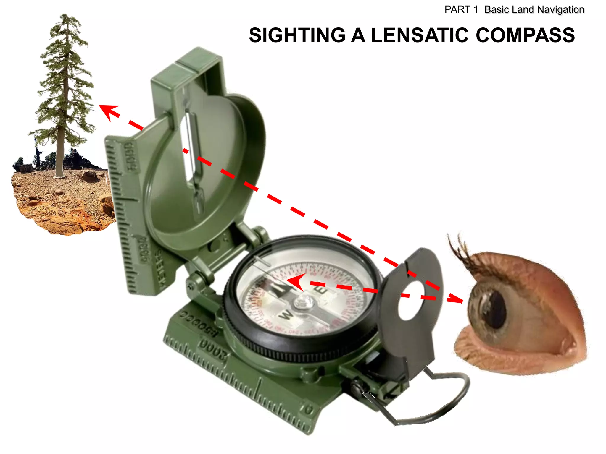
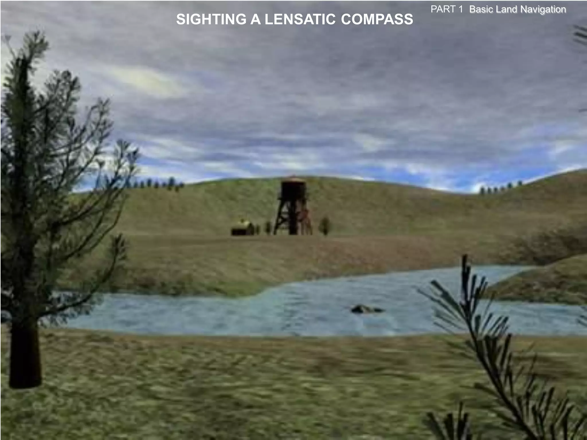
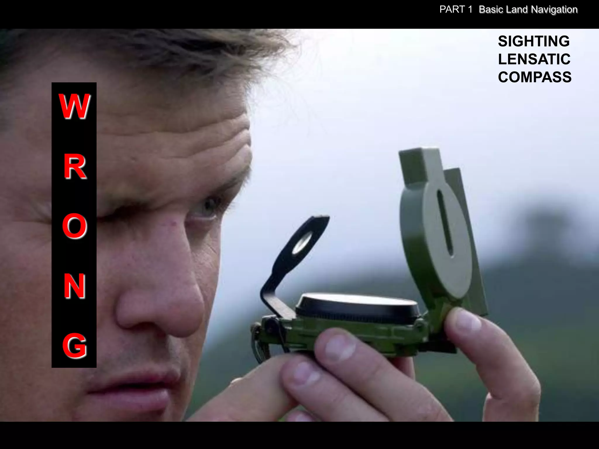
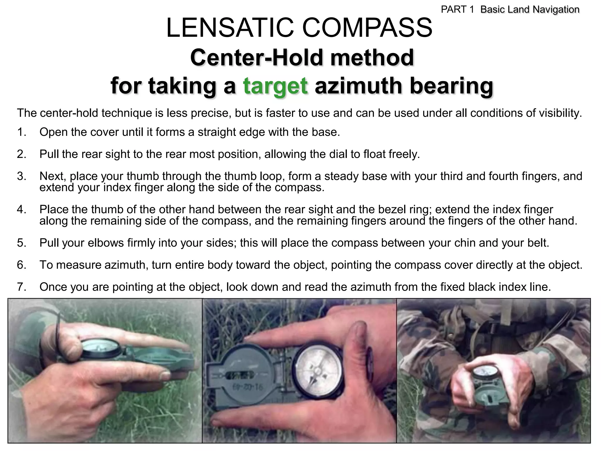
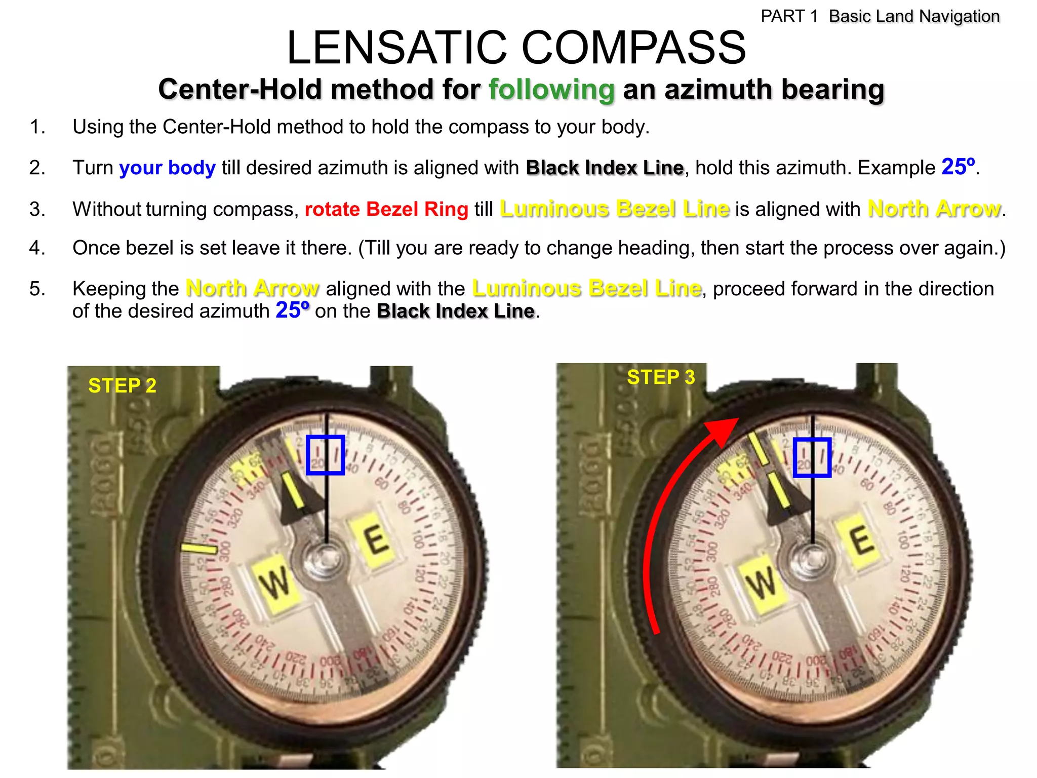
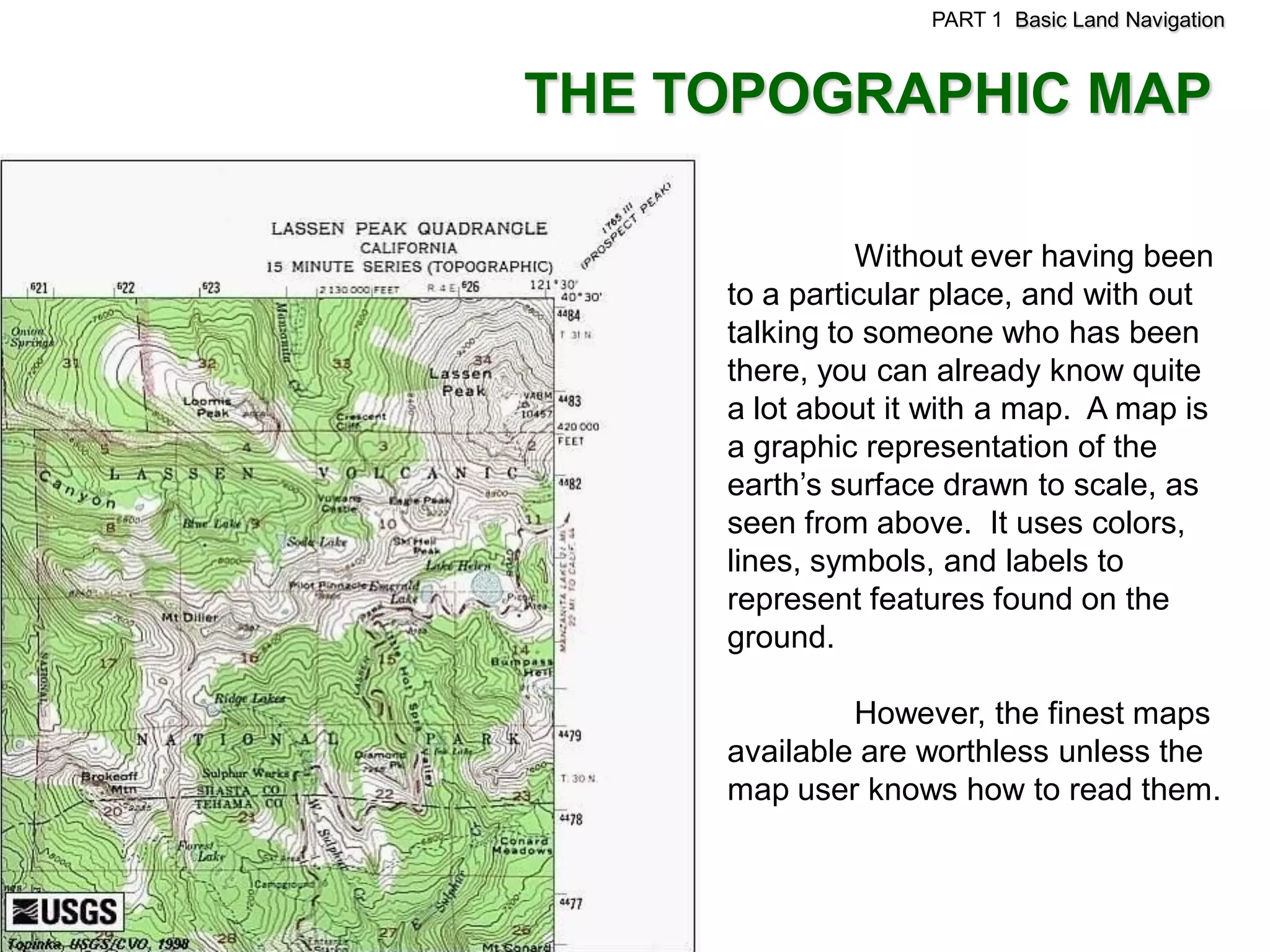
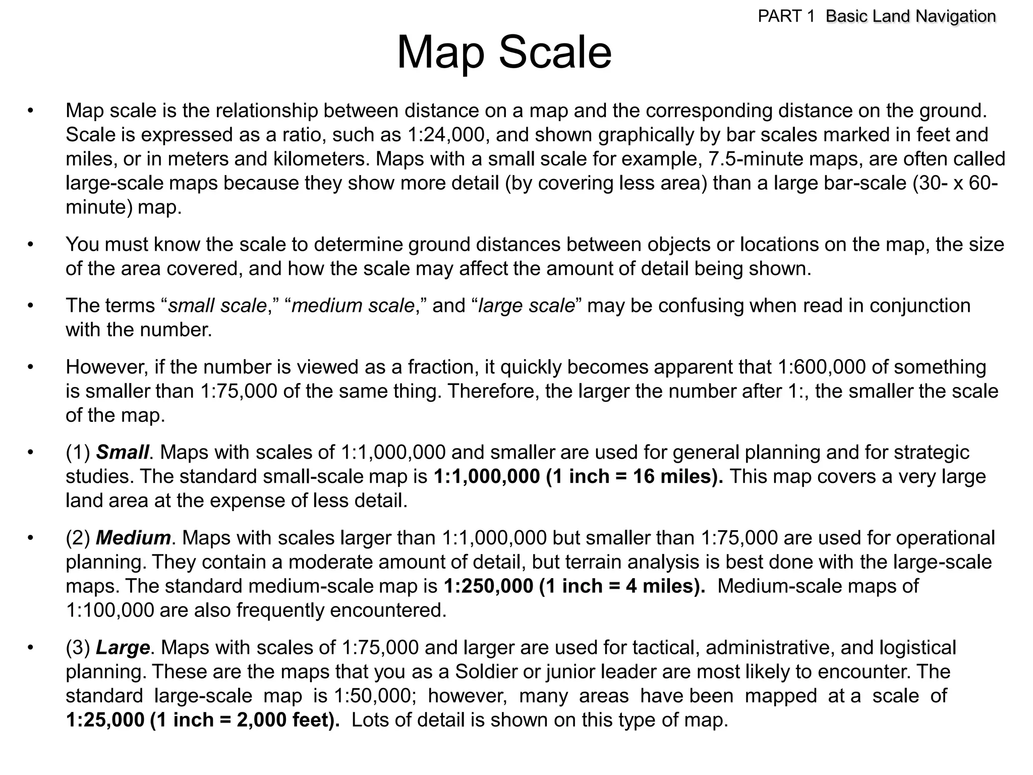
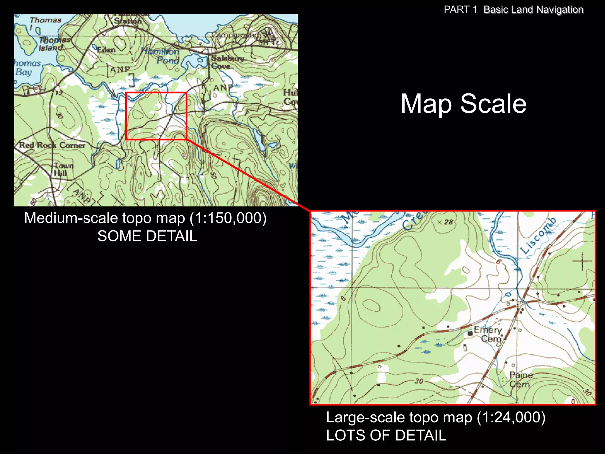
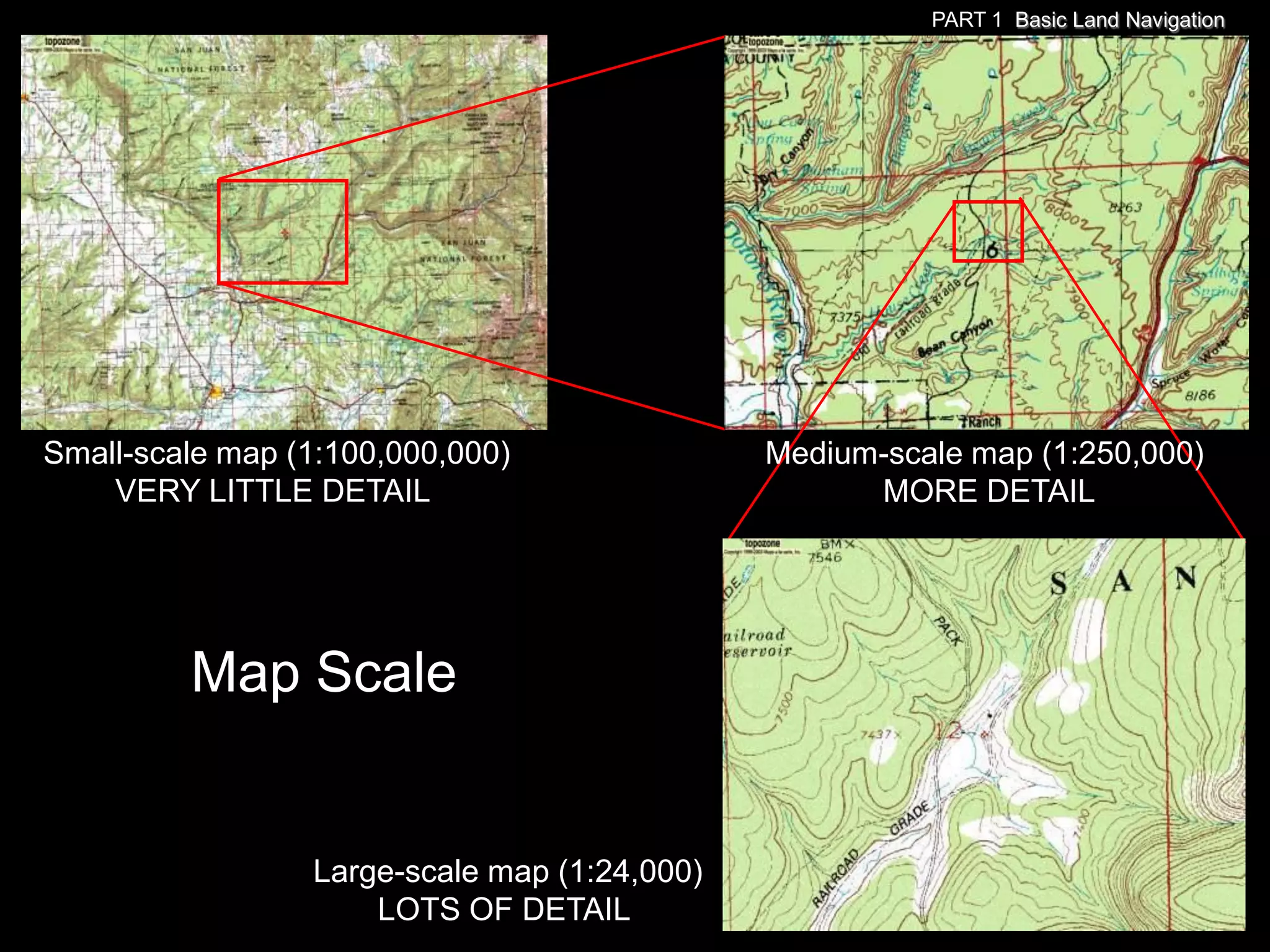
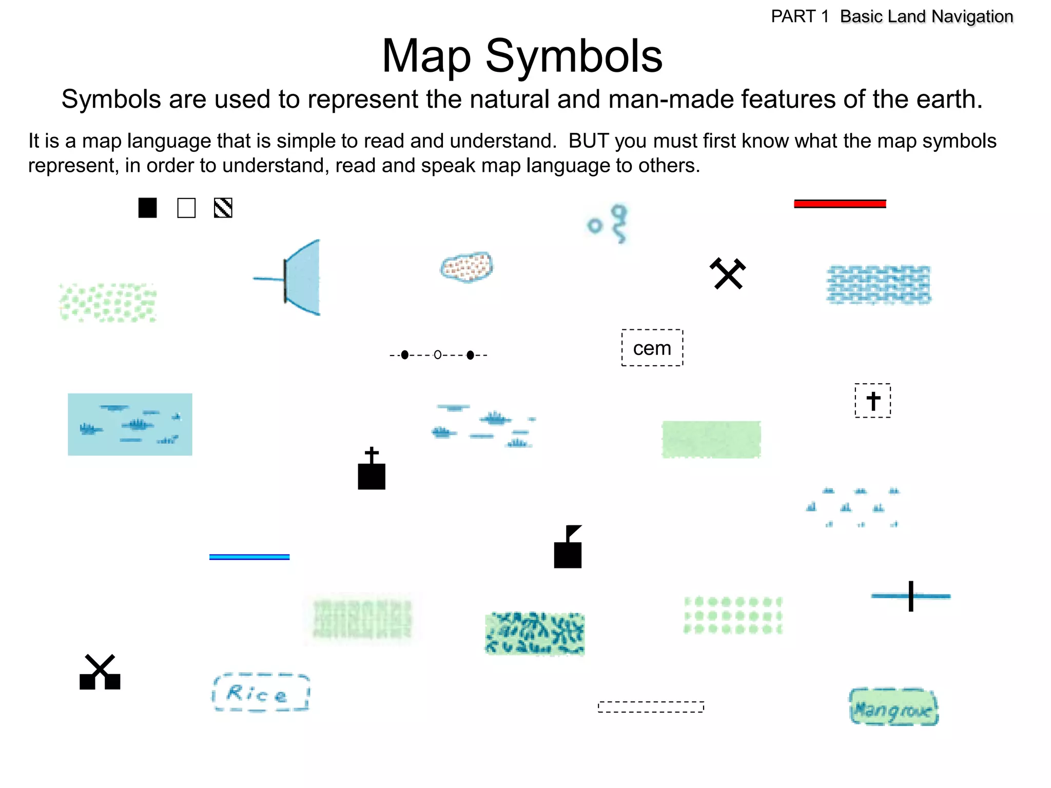
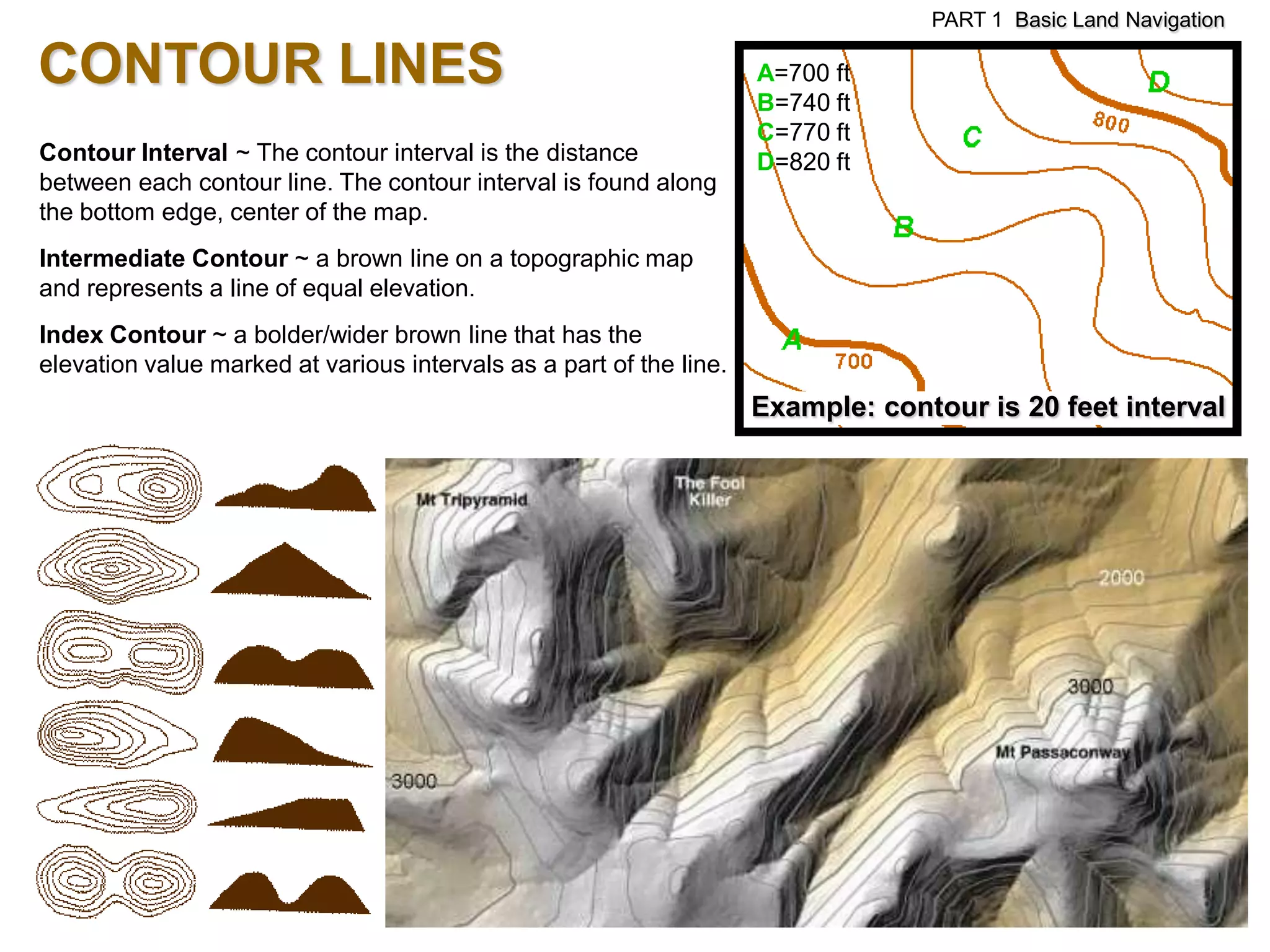
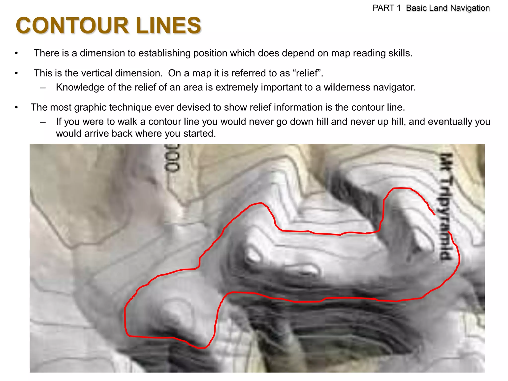
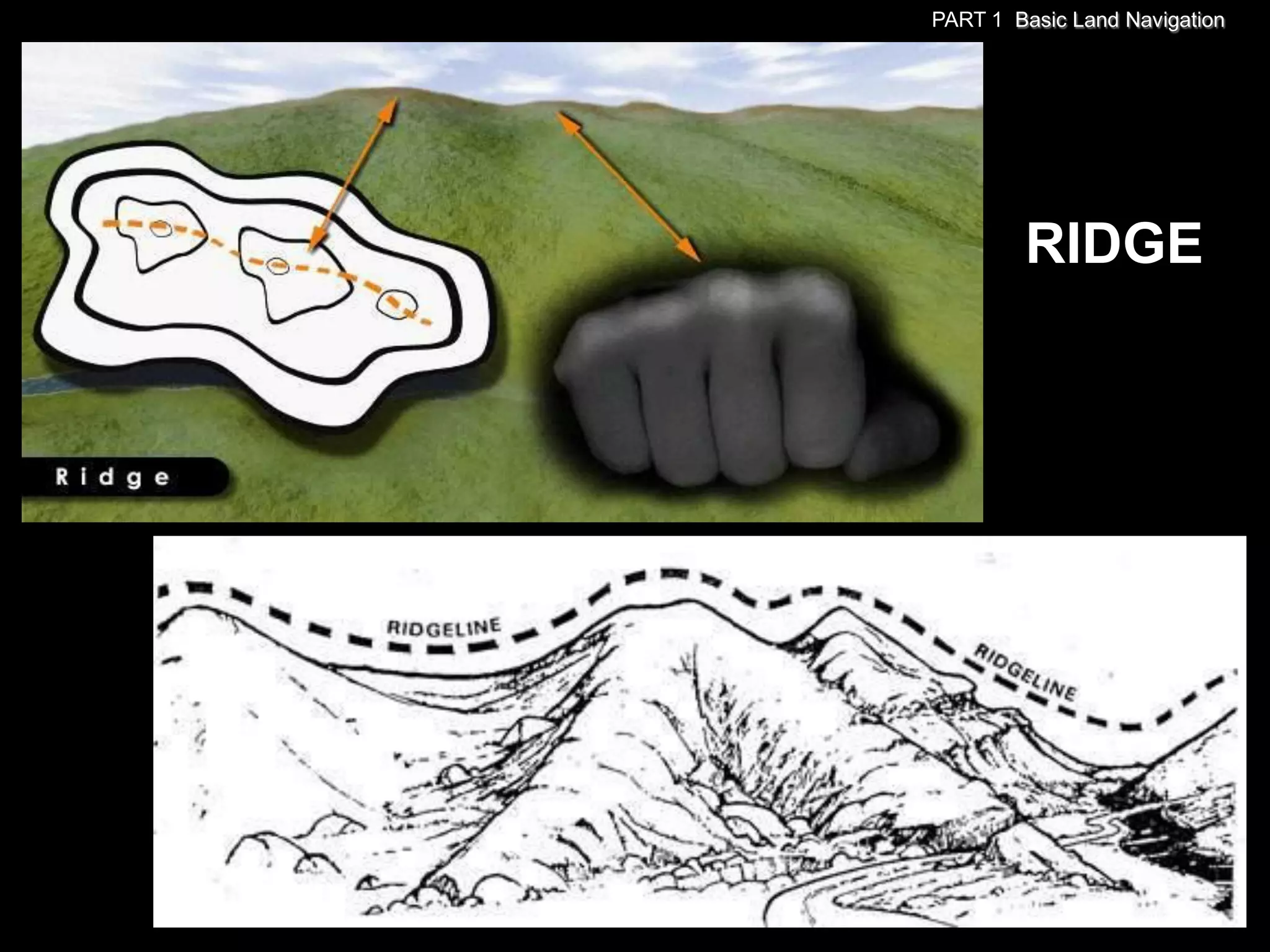
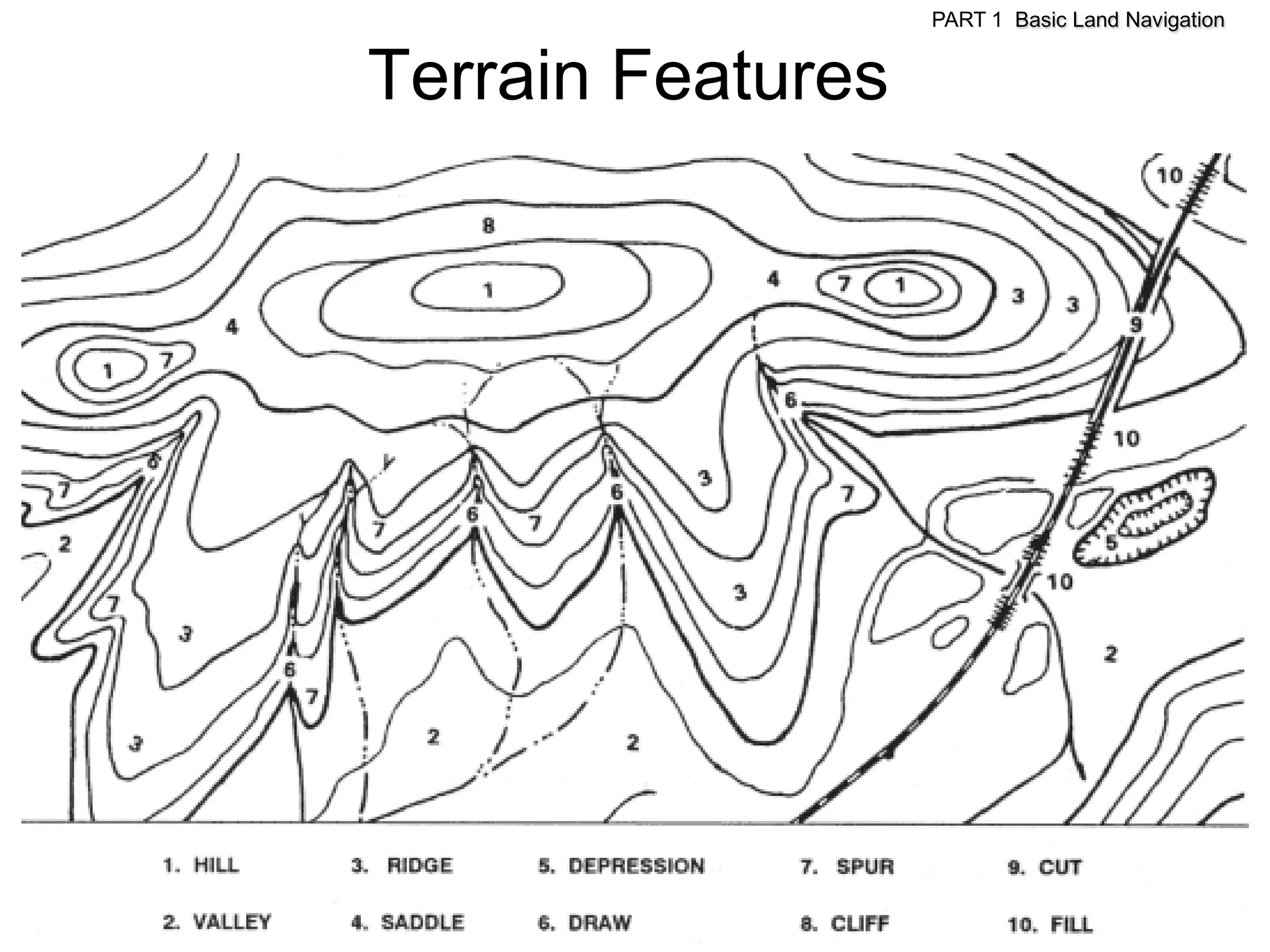
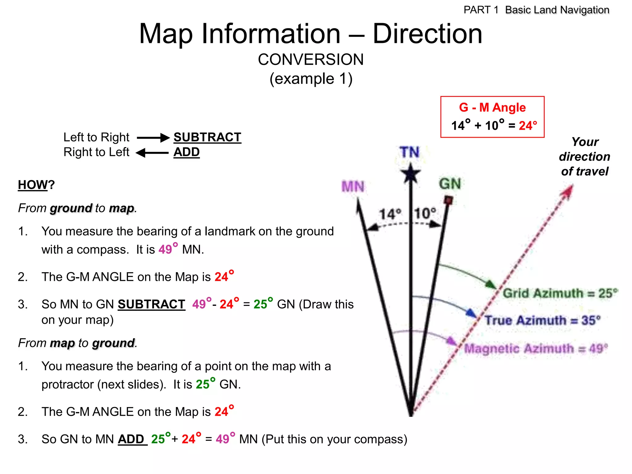
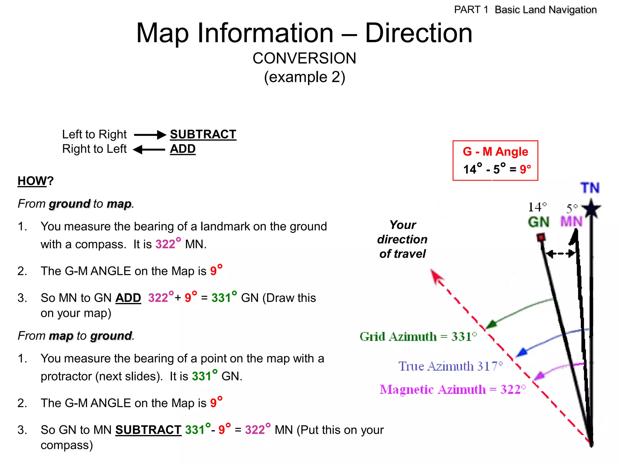
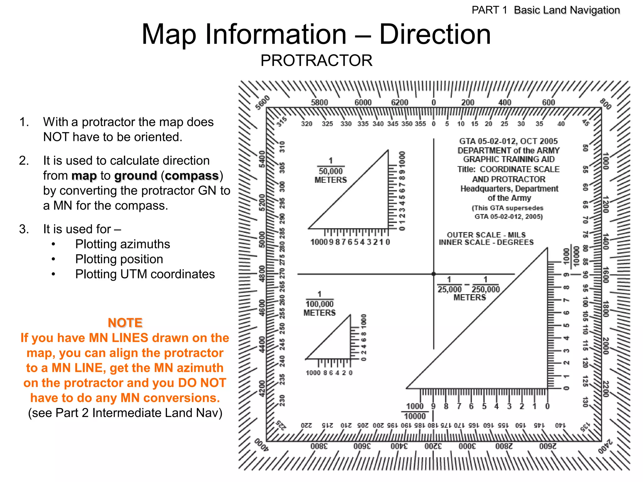
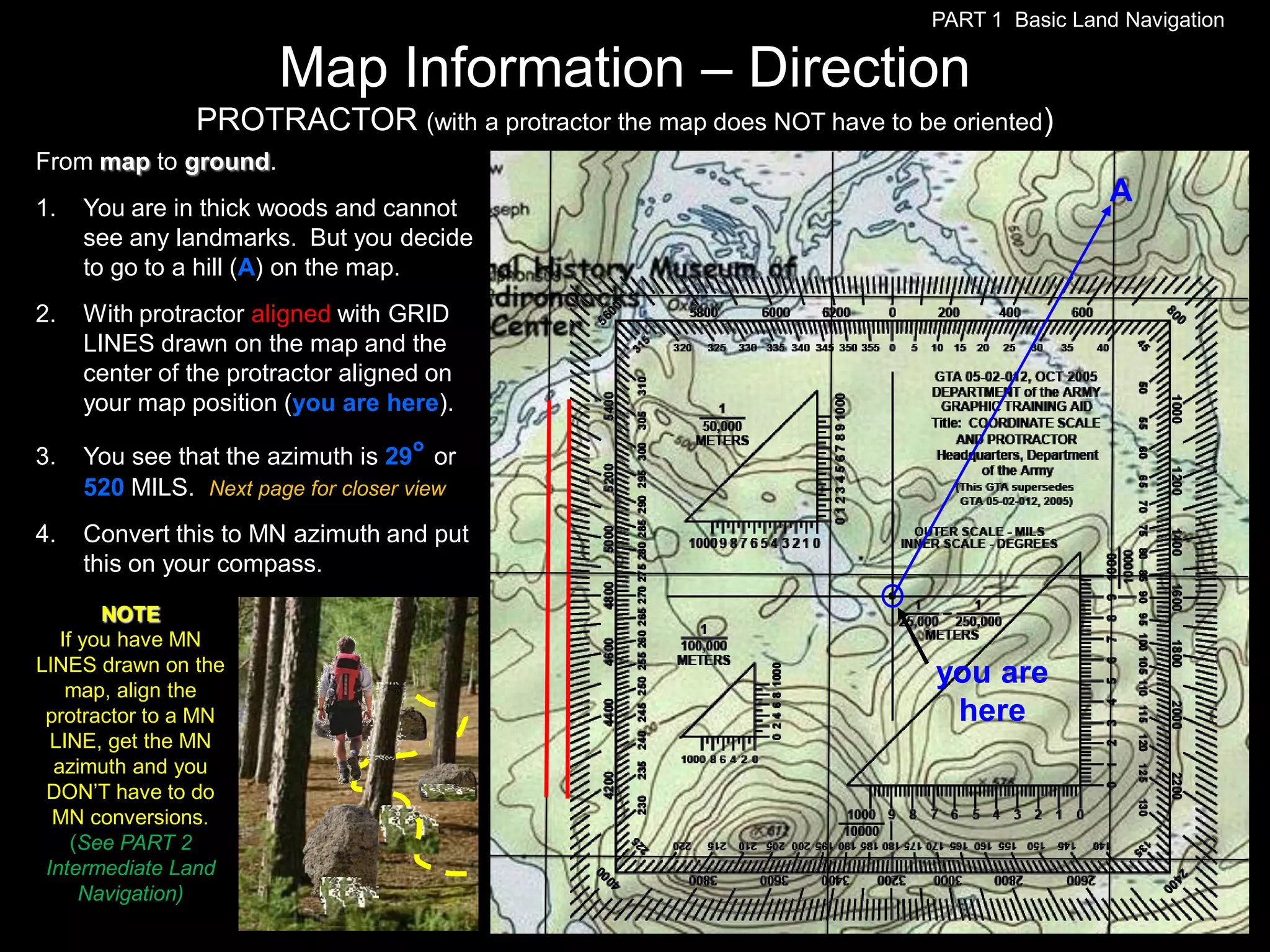
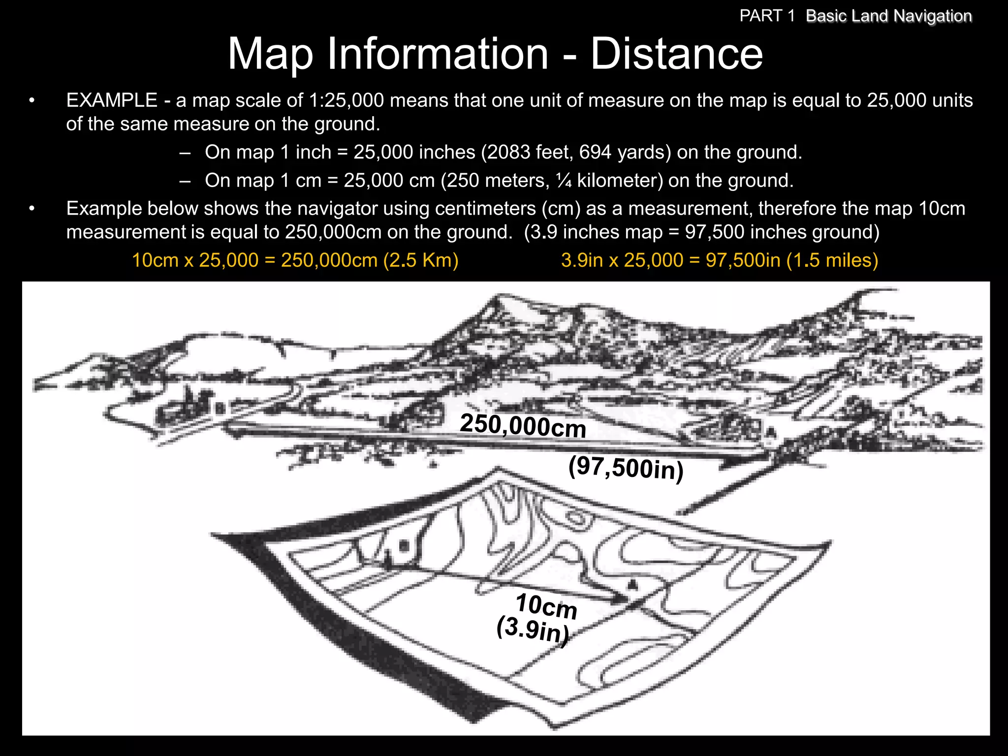
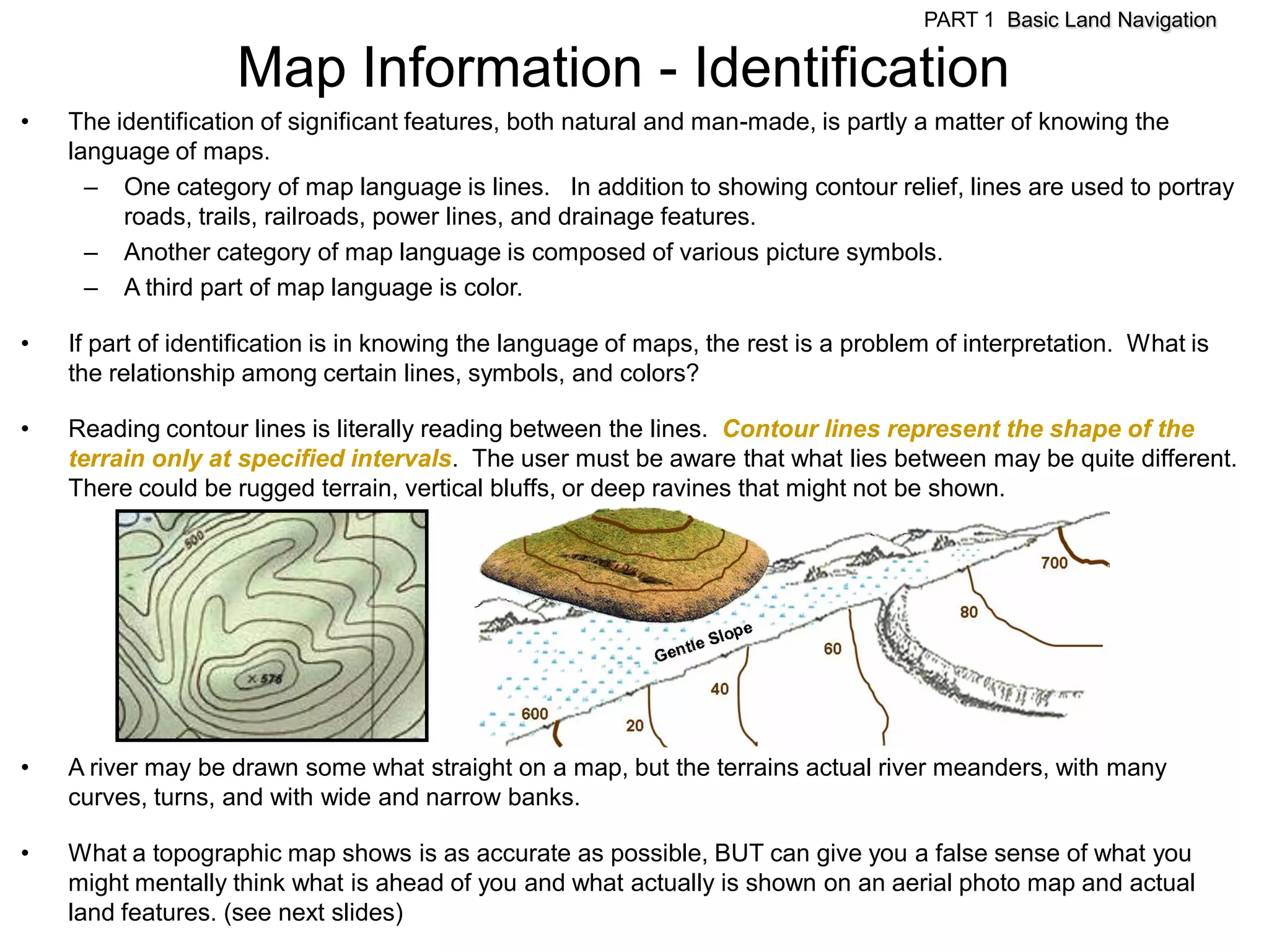
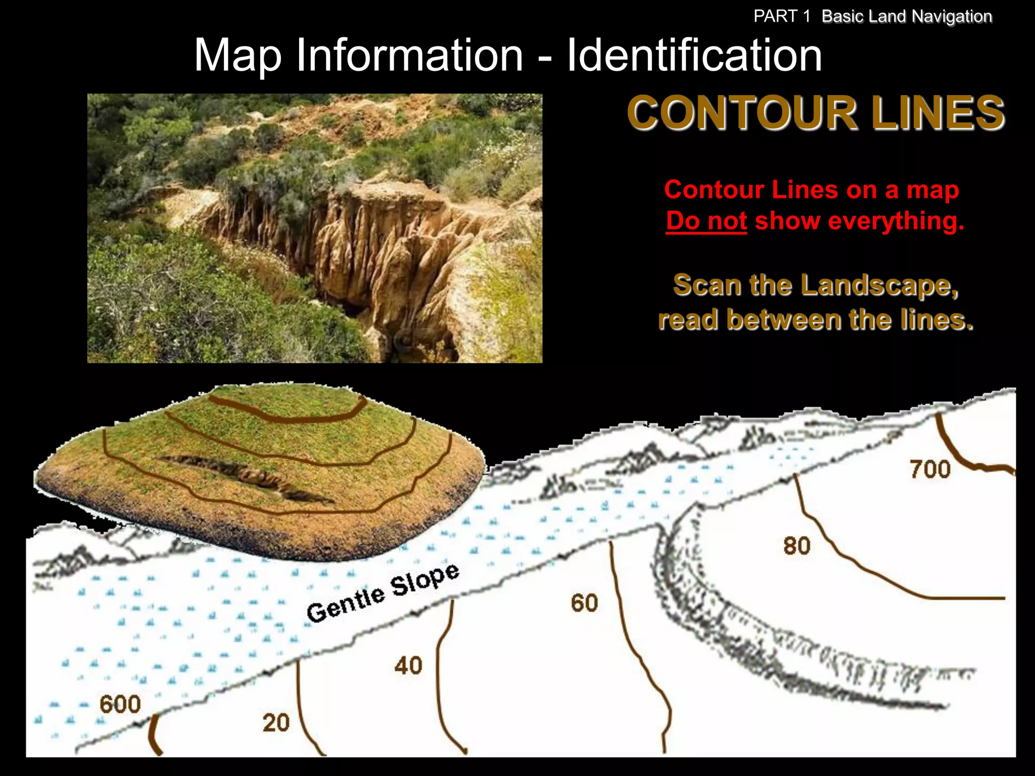
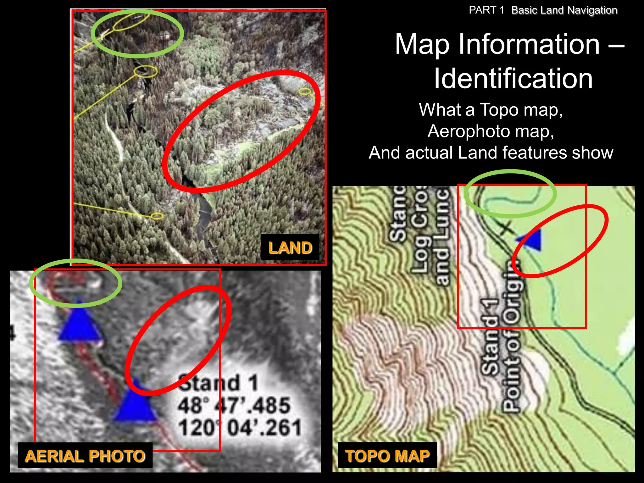
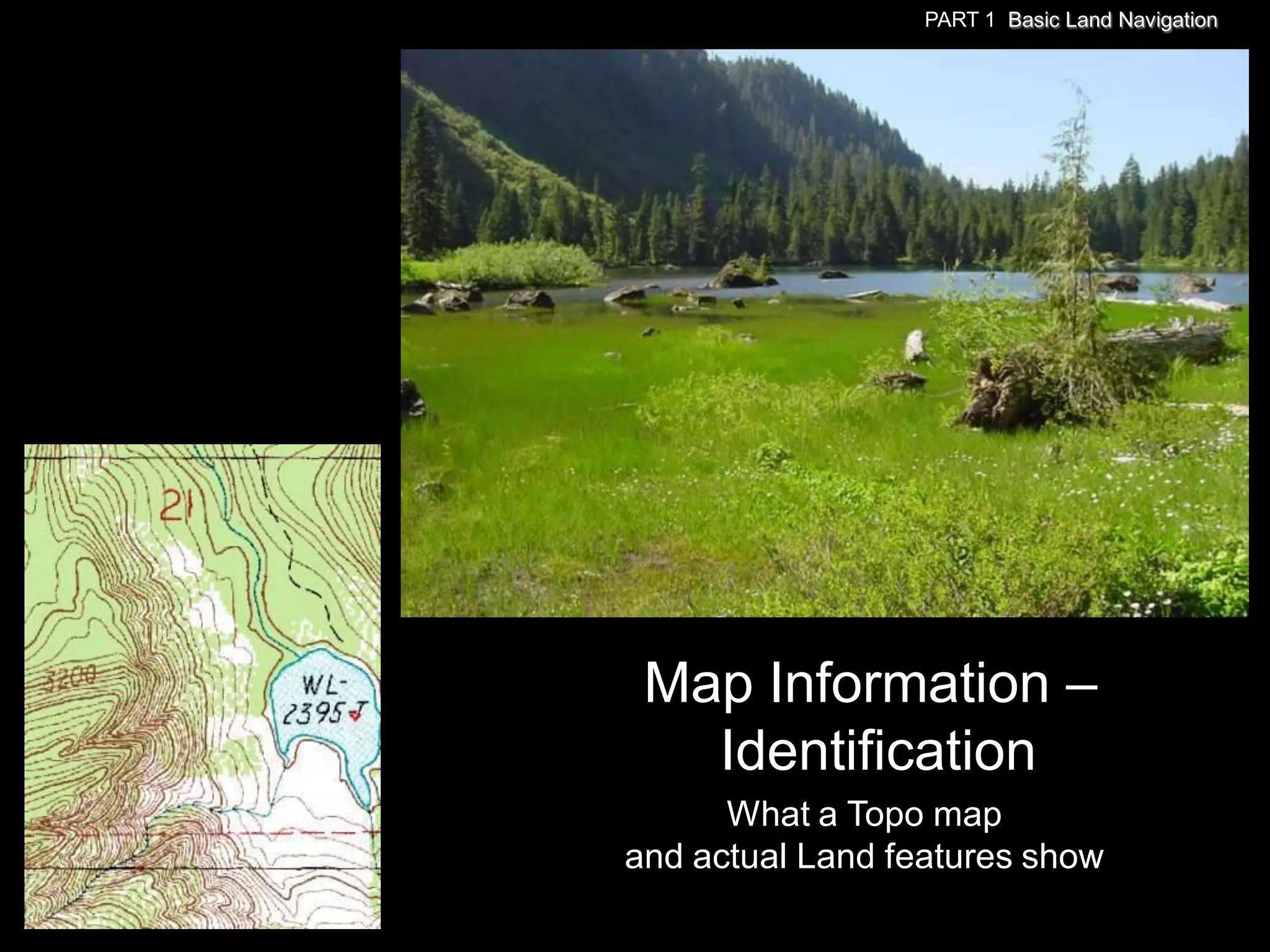
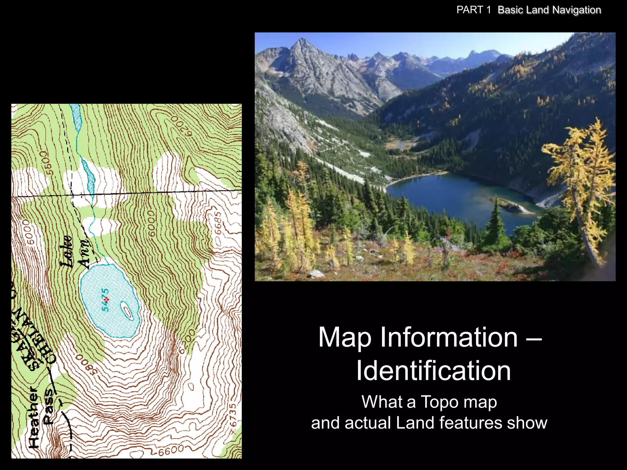
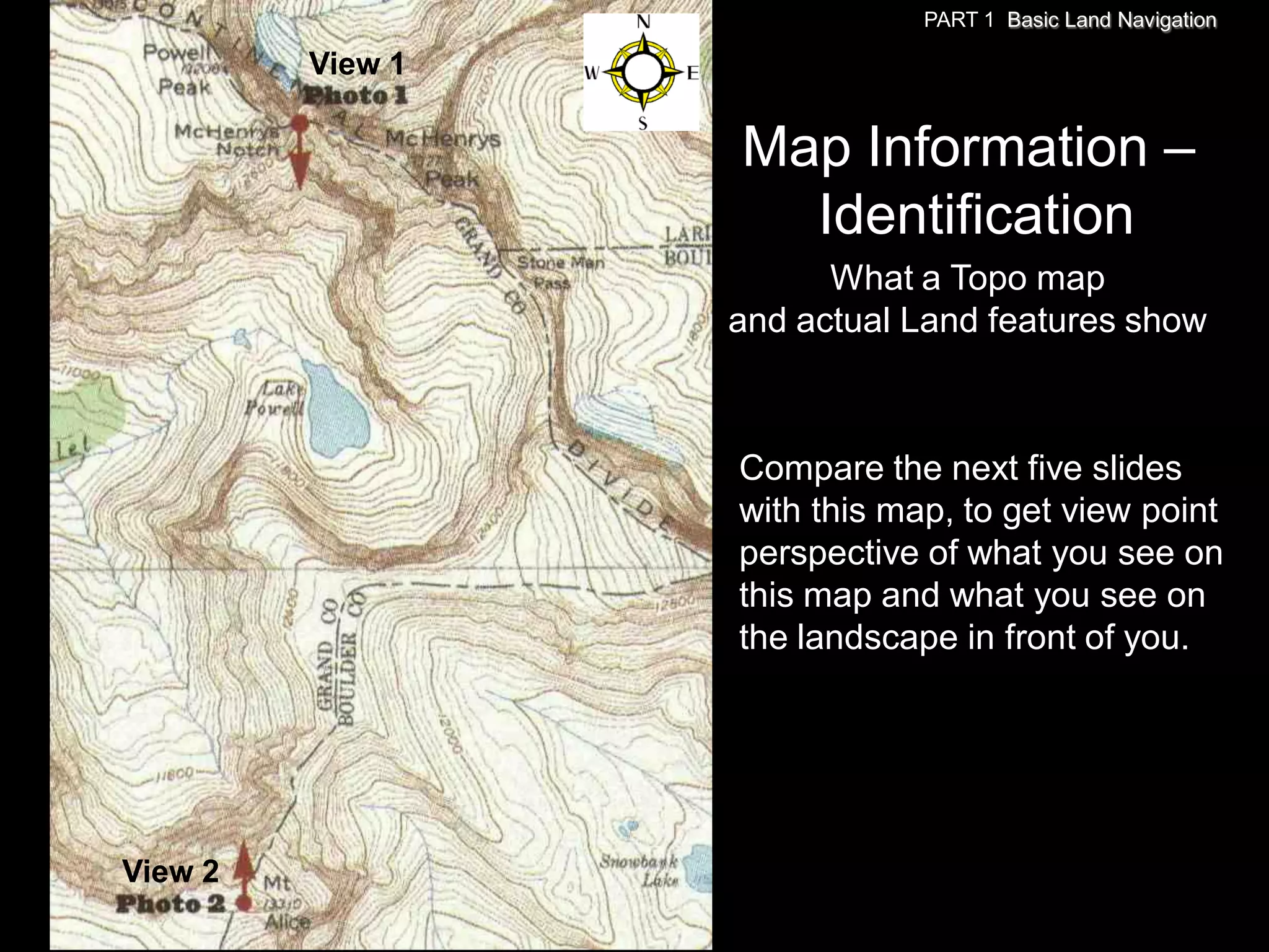
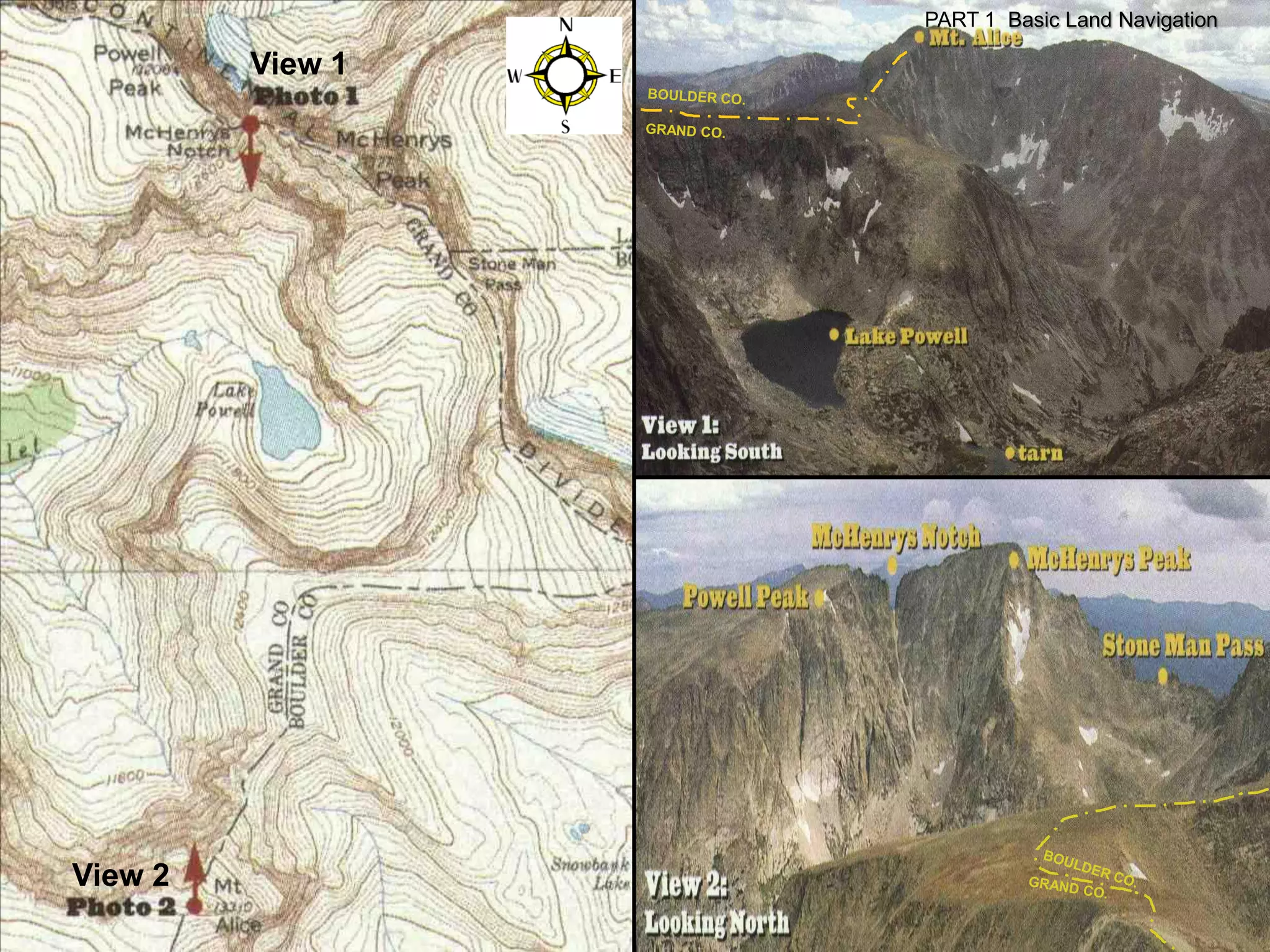
SlideShare a Scribd company logo
1 of 122
Download to read offline
PART 1
     BASIC
LAND NAVIGATION
PART 1 Basic Land Navigation


USING THE
 MILITARY
LENSATIC
COMPASS
PART 1 Basic Land Navigation


     WARNING
This presentation is intended as a
    quick summary, and not a
 comprehensive resource. If you
 want to learn Land Navigation in
 detail, either buy a book; or get
someone, who has the knowledge
and skills, to teach you in person.
PART 1 Basic Land Navigation


           NOTE
To get the ideas across presented on
these slides, many figures, pictures,
and calculations may not be to scale
 and may be exaggerated for clarity.
PART 1 Basic Land Navigation


                             Note:
Prior to being issued any training *equipment, you will
be required to sign a “statement of liability” agreeing
        to pay for anything you damage or lose.


  All items will be inspected and inventoried prior to
 your signature and at the end of the training day too.


  If you do not intend to sign this statement, then you
                 may be denied training.
* You may use your own equipment.
PART 1 Basic Land Navigation


Any Questions?
PART 1 Basic Land Navigation


LAND NAVIGATION WITH MAP
   AND LENSATIC COMPASS
PART 1 Basic Land Navigation


                              LAND NAVIGATION
Why Learn Land Navigation? Training and practicing land navigation on foot
provides the following everyday navigation (how not to get lost) benefits;
- Tracking present location (Where am I ?)
- Determining Distance (How far is it and am I there yet ?)
- Sense of direction (Where do I want to go and where am I actually going ?)
- How to read a topographic map (Do I understand the map ?)
-Terrain and map association (What hill or river am I looking at ?)
- Spatial skills (Can I mentally visualize the landscape in 3D ?)
- Planning safe, practical routes (Take a long safe route or a short risky route ?)
- And more Navigational skills
The best way to learn LAND NAVIGATION is to get "dirt time", that is, get out there with a map and compass!
Navigation is not about finding yourself after you are lost (although that’s what happens sometimes); it’s about
keeping track of your position as you move away from a known point. As you move you have to remain
cognizant of the terrain you are leaving, of the terrain you are passing, and of the terrain that is ahead.
Navigation in the wilderness means knowing your starting point, your destination, and your route to get there.
These skills will allow you to venture farther off the beaten path than you ever thought before.
PART 1 Basic Land Navigation

        THIS PRESENTATION IS DIVIDED INTO FOUR PARTS
________________________________________________________________________________________________________________________________________________________


             PART 1          Basic Land Navigation
                              The Lensatic Compass
                              The Topographic Map
                              The Land and Map Association
             PART 2          Intermediate Land Navigation
                              Making Sense of Direction
                             Tracking Present Location
                              Determining Travel Distance
             PART 3          Advance Land Navigation
                              Planning to Navigate
                              Navigation Methods to Stay On Course
                              Additional Skills of Land Navigation
             PART 4          Expert Land Navigation
                              Navigation in different types of Terrain
                              Night Navigation
                              Sustainment
PART 1 Basic Land Navigation


Any Questions?
PART 1 Basic Land Navigation


                PART 1
BASIC LAND NAVIGATION
   • The Lensatic Compass
     – Description
     – Parts and Features

   • The Topographic Map
     – Description
     – How to Read

   • The Land
     – Terrain Features
     – Terrain and Map Association
PART 1 Basic Land Navigation


THE LENSATIC COMPASS
  The genuine Lensatic compass differs
  from the type most hikers are familiar
  with, the traditional "orienteering"
  compasses. The Lensatic, a design
  preferred by military forces for its
  precision and durability, is designed to
  take hyper-accurate bearings for land
  navigation and directing artillery fire!
PART 1 Basic Land Navigation

                         LENSATIC COMPASS
                            DESCRIPTION
•   Preferred by military for its precision and durability, and its hyper-accuracy in land
    navigation and combat.
•   Battle tested - shock, water, sand proof, and functional from -50ºF to +150ºF.
•   Uses a retractable lens to read the bearing while simultaneously sighting an object.
•   With the Lensatic you just point and shoot one target and immediately move on to the next.
•   Luminous Lights allow for navigation in low-light conditions and night navigation.
•   Equipped with a magnifying lens, sight wire, and dial graduations in both degrees and mils
    to ensure accurate readings.
•   Copper induction dampening system slows the rotation of the magnet without the use of
    liquids. Retractable lens locks the dial jewel bearing when stowed to lessen wear and tear.
•   Employs a "Card" type compass Dial, and this makes for single handed operation.
    (Most magnetic "needle" type, always requires 2 hands.)
•   A 'deep-well' design is used to allow the compass to be used globally with little or no effect
    in accuracy caused by a tilting compass dial.
•   Lensatic sighting compasses are so simple and rugged and incredibly easy to use that it is
    no wonder they are the standard type used for navigation by the U. S. Military.
PART 1 Basic Land Navigation

                           LENSATIC COMPASS
                          GENUINE or IMITATION
Cheap Lensatic Copies
   When someone tried to buy a genuine CAMMENGA LENSATIC COMPASS from websites, they came
across a whole raft of cheap imitations. Most outlets tell you they are selling ‘Military Style’ Lensatic
compasses (fake, inaccurate, missing features) – but some claim to offer U.S. Government Military Lensatic
compasses for just $14.95, which are also fake cheap imitations.
   Cheap copies break easily, are not accurate, have false features displayed on the compass
glass face and will mislead you.
The genuine lensatic compass used by the military is very durable, accurate, and easy
to use. It can survive rough handling and harsh environments.


Buy the Genuine Article
Purchasing a genuine
CAMMENGA LENSATIC
COMPASS is easy, go to
www.cammenga.com

Click below
Lensatic Compass Evaluation.pdf
to read about the comparison
of compasses…
    “orienteering compass
               vs.
      lensatic compass”.
PART 1 Basic Land Navigation


Any Questions?
PART 1 Basic Land Navigation

                         LENSATIC COMPASS
        PARTS and Features of a Lensatic compass
                                                            Bezel                   3. LENS
                                                  Floating Dial
                                                                                     REAR
                                         Fixed Index Line
                                                                                      SITE
                            Luminous Magnetic Arrow                 Sighting Slot
Luminous Sighting Dots
                            Luminous Bezel Line
        Sighting Wire
                         Luminous Heading
                                                                                        Lens


                                                                               Lanyard Ring

                                                                                    Thumb Loop
                            Graduated Straight Edge

                 1. COVER                             2. BASE
PART 1 Basic Land Navigation

                         LENSATIC COMPASS
     Cover - Protects the floating dial and other parts of the compass when closed.


•   Sighting Wire - front sight used with rear sight, for sighting landmarks for azimuth headings.
•   Luminous Sighting Dots – used in low-light condition and night navigation. Also a visual
    queue on aligning your body with the compass during night navigation.
•   Graduated Straight Edge - upper half of a standard 1:50,000 scale map ruler, for measuring
    distances on a map.
PART 1 Basic Land Navigation


                          LENSATIC COMPASS
    Base - The main body of the compass.       If, for any reason, the lensatic compass
    were to malfunction, the base would be the piece that you would want to still work.
•    Bezel Ring – device clicks when turned; full 360° rotation is 120 clicks; each click equals 3°.
•    Luminous Bezel Line – Used to mark a course direction during day or night navigation.
•    Floating Dial – black scale (mils), red scale (degrees), set in a deep tub for global use.
•    Luminous Heading – to read azimuth heading in low-light or night conditions.
•    Luminous Magnetic Arrow – always points to magnetic north.
•    Thumb Loop – to hold compass with the thumb.
•    Fixed Index Line – azimuth heading.
•    Lanyard Ring – for string or rope.

NOTE:
The only way for the compass
to malfunction is for the user to
misuse and abuse the compass.
PART 1 Basic Land Navigation

FLOATING DIAL SCALE           BLACK RING
                      Mils - is used mainly in artillery, tank, and
                      mortar gunnery. AND is also used for very
                      accurate azimuth land navigation.
                      • 6400 Mils to a Circle
                      • Distance Between Small Marks = 20 Mils
                      • Distance Between Big Marks = 100 Mils
                      • Distance Between Numbers = 200 Mils
                                      N = 64 (6400)
                                      E = 16 (1600)
                                      S = 32 (3200)
                                      W = 48 (4800)
                                 8.89 Mils = ½ Degree
                                  17.78 Mils = 1 Degree


                                  LENSATIC
                                  COMPASS
PART 1 Basic Land Navigation

FLOATING DIAL SCALE           BLACK RING
                      Mils - is used mainly in artillery, tank, and
                      mortar gunnery. AND is also used for very
                      accurate azimuth land navigation.
                      • 6400 Mils to a Circle
                      • Distance Between Small Marks = 20 Mils
                      • Distance Between Big Marks = 100 Mils
                      • Distance Between Numbers = 200 Mils
                                      N = 64 (6400)
                                      E = 16 (1600)
                                      S = 32 (3200)
                                      W = 48 (4800)
                                 8.89 Mils = ½ Degree
                                  17.78 Mils = 1 Degree
                                      RED RING

                        Degrees – common unit of measure is
                        the degree (º).
                        • 360 Degrees to a Circle
                        • Distance Between Red Marks = 5º
                        • Distance Between Big Marks = 10º
                        • Distance Between Red Numbers = 20º
                                         N = 0º
                                         E = 90º
                                        S = 180º
                                        W = 270º
PART 1 Basic Land Navigation


Any Questions?
PART 1 Basic Land Navigation

                        LENSATIC COMPASS
                  GRADUATED STRAIGHT EDGE


                         Approximately 1 inch (every 13 ticks)

                                                 Exactly 1 cm (every 5 ticks)
Used to take distance measurements from point ―A‖ to point ―B‖                   ZERO
on maps; in conjunction with the distance bar scales on the map.
                             NOTE
   When used on a 1:50,000 map, each tick mark on the edge
    represents 100 meters (107 yards) of ground distance.
PART 1 Basic Land Navigation

                          LENSATIC COMPASS
                          Lens Rear Site - Sighting device.

•   Lens - used to read the dial.
•   Rear Site - used in conjunction with the front site wire for sighting on objects.

                     NOTE:
The Lens Rear Sight also serves as a locking device
and locks the dial jewel bearing to protect from wear
and tear when closed. Also the rear sight must be
opened more than 45° to allow dial to float freely.

When traveling make sure that the rear sight is
totally folded down as this will lock the floating
dial and prevent vibration, as well as protect the
crystal and rear sight from being damaged.
PART 1 Basic Land Navigation


Any Questions?
PART 1 Basic Land Navigation

                            LENSATIC COMPASS
                           HANDLING A COMPASS
When buying a new compass check . . .
•   That the dial does not stick
•   Sighting wire is not bent
•   Glass and other parts are not broken
•   Numbers on the dial are legible
•   Check for accuracy along a known line of direction
     — Discard any type of compass with more than a 3° +/- variation.
     — Lensatic compass is accurate to a ½° degree (better when using the mils scale).
•   When traveling make sure that the rear sight is totally folded down as this will lock the floating
    dial and prevent vibration, as well as protect the crystal and rear sight from being damaged.
EFFECTS OF METAL AND ELECTRICITY – these sources affect the performance of a compass during use.
•   180 feet / 55 meters           High tension power lines
•   33 feet / 10 meters            Truck, car, Barbed wires
•   6 feet / 2 meter               Hunting rifle
•   1 feet / ½ meter               Knife, flashlight, binoculars, camera
•   Inches / centimeters           Belt buckle, paper clip, jewelry, etc.
•   Misc distances                 any local geological magnetic rocks.
PART 1 Basic Land Navigation

                              LENSATIC COMPASS
                            INSPECTING A COMPASS
Compasses are delicate instruments and should be cared for accordingly. A detailed
inspection is required when first obtaining and using a compass. Important serviceability
checks are outlined below:
VISUAL INSPECTION
•   Your compass should be opened to see that the cover glass is not broken, clouded, or
    cracked and that the compass dial does not stick.

•    The front cover should be inspected to see if the cover sighting wire is missing or
     bent. If it is, use the center of the opening for sighting purposes, not the wire.

•    The eyepiece should be placed flat against the cover glass. The index line on the cover glass should bisect the sight slot.
     Then, with the compass closed, it should be noted that the sighting wire also bisects the sight slot.
       This procedure will ensure that the eyepiece is not bent. Gently bend the eyepiece back into proper alignment, if
           necessary.

•    Check the bezel ring around the face of the compass; it should make a distinct click as it is rotated. If it does not click,
     you will have to use an alternate method for night azimuth settings.

MAINTENANCE
• The lensatic compass is built to detailed specifications that were developed in an attempt to increase its serviceable life.
  Adherence to very simple maintenance procedures will significantly increase the life of the lensatic compass. Maintenance
  procedures are outlined below:

•   Rinse in fresh water. This is extremely important, especially after exposure to salt water.
•   Brush off dirt and grime. Ensure the "ridges" on the bezel ring are free of dirt. Check movement of the rear sight to
    ensure it is free moving.
PART 1 Basic Land Navigation

                             LENSATIC COMPASS
                                CALIBRATION
A compass in good working condition is very accurate, but it should be checked periodically
on a known line of direction. This process is called compass calibration.

CALIBRATION
•  Note the calibration point azimuth. This is the known magnetic azimuth
   from the calibration point to a designated point.
•   Shoot an azimuth from the calibration point to the designated point
    utilizing the compass-to-cheek technique (described in detail later in this
    handout).
•    Ensure you check for effects on your compass from your eyeglasses,
    watches, rings, etc. If you wear these items in the field, ensure you wear
    them when calibrating your compass.
Compare azimuths:
•  If your compass shot an azimuth greater than the calibration point azimuth, then you must add the
   difference between the two azimuths (the calibration point value) to your computed magnetic azimuth.
      Conversely, you must also ensure you subtract this value when converting from an actual compass
          (magnetic) azimuth to a grid azimuth.
•   If your compass shot an azimuth less than the calibration point azimuth, then you must subtract the
    difference between the two azimuths (the calibration point value) from your computed magnetic azimuth.
       Conversely, you must also ensure you add this value when converting from an actual compass
           (magnetic) azimuth to a grid azimuth.
PART 1 Basic Land Navigation


Any Questions?
PART 1 Basic Land Navigation


  HOW TO SIGHT
        A
LENSATIC COMPASS
PART 1 Basic Land Navigation

                   SIGHTING A LENSATIC COMPASS
                 Compass-to-Cheek method
             for taking a target azimuth bearing
•   The compass-to-cheek technique is used almost exclusively for sighting, and it is the best
    technique for this purpose.
•   It is the most efficient technique for taking an accurate azimuth bearing.
PART 1 Basic Land Navigation


SIGHTING A LENSATIC COMPASS
PART 1 Basic Land Navigation

SIGHTING A
LENSATIC
COMPASS
PART 1 Basic Land Navigation

SIGHTING A LENSATIC COMPASS
PART 1 Basic Land Navigation


Any Questions?
PART 1 Basic Land Navigation
SIGHTING A LENSATIC COMPASS
PART 1 Basic Land Navigation
SIGHTING A LENSATIC COMPASS


                  65° AZIMUTH
                     (11.5m = 1,150mils)
PART 1 Basic Land Navigation

                   SIGHTING A LENSATIC COMPASS
                 Compass-to-Cheek method
             for taking a target azimuth bearing
                                    this is worth repeating
•   The compass-to-cheek technique is used almost exclusively for sighting, and it is the best
    technique for this purpose.
•   It is the most efficient technique for taking an accurate azimuth bearing.
PART 1 Basic Land Navigation

             SIGHTING
             LENSATIC
             COMPASS

R
I
G
H
T
PART 1 Basic Land Navigation

             SIGHTING
             LENSATIC
             COMPASS

R
I
G
H
T
PART 1
    Basic Land Navigation

        SIGHTING
        LENSATIC
        COMPASS

W
R
O
N
G
PART 1
    Basic Land Navigation

    SIGHTING
    LENSATIC
    COMPASS

R
I
G
H
T
PART 1
    Basic Land Navigation

    SIGHTING
    LENSATIC
    COMPASS

R
I
G
H
T
PART 1
    Basic Land Navigation

    SIGHTING
    LENSATIC
    COMPASS

R
I
G
H
T
PART 1 Basic Land Navigation


               SIGHTING
               LENSATIC
               COMPASS

W
R
O
N
G
PART 1 Basic Land Navigation


               SIGHTING
               LENSATIC
               COMPASS

R
I
G
H
T
PART 1 Basic Land Navigation


               SIGHTING
               LENSATIC
               COMPASS

W
R
O
N
G
PART 1 Basic Land Navigation


               SIGHTING
               LENSATIC
               COMPASS

W
R
O
N
G
PART 1 Basic Land Navigation


Any Questions?
PART 1 Basic Land Navigation

                               LENSATIC COMPASS
                            Center-Hold method
                    for taking a target azimuth bearing
The center-hold technique is less precise, but is faster to use and can be used under all conditions of visibility.
1.   Open the cover until it forms a straight edge with the base.
2.   Pull the rear sight to the rear most position, allowing the dial to float freely.
3.   Next, place your thumb through the thumb loop, form a steady base with your third and fourth fingers, and
     extend your index finger along the side of the compass.
4.   Place the thumb of the other hand between the rear sight and the bezel ring; extend the index finger
     along the remaining side of the compass, and the remaining fingers around the fingers of the other hand.
5.   Pull your elbows firmly into your sides; this will place the compass between your chin and your belt.
6.   To measure azimuth, turn entire body toward the object, pointing the compass cover directly at the object.
7.   Once you are pointing at the object, look down and read the azimuth from the fixed black index line.
PART 1 Basic Land Navigation

                             LENSATIC COMPASS
               Center-Hold method for following an azimuth bearing
1.   Using the Center-Hold method to hold the compass to your body.

2.   Turn your body till desired azimuth is aligned with Black Index Line, hold this azimuth. Example 25º.

3.   Without turning compass, rotate Bezel Ring till Luminous Bezel Line is aligned with North Arrow .
4.   Once bezel is set leave it there. (Till you are ready to change heading, then start the process over again.)

5.   Keeping the North Arrow aligned with the Luminous Bezel Line, proceed forward in the direction
     of the desired azimuth 25º on the Black Index Line.


      STEP 2                                                         STEP 3
PART 1 Basic Land Navigation


Any Questions?
PART 1 Basic Land Navigation


THE TOPOGRAPHIC MAP

               Without ever having been
     to a particular place, and with out
     talking to someone who has been
     there, you can already know quite
     a lot about it with a map. A map is
     a graphic representation of the
     earth’s surface drawn to scale, as
     seen from above. It uses colors,
     lines, symbols, and labels to
     represent features found on the
     ground.

              However, the finest maps
     available are worthless unless the
     map user knows how to read them.
PART 1 Basic Land Navigation

                              TOPOGRAPHIC MAP
                                DESCRIPTION
•   Reading a map is a language composed of lines, colors, and symbols.
•   Five basic colors are used for Topographic Maps.
     – Brown (Contour Lines)
     – Black (Man Made Features, Roads, Trails)
     – Blue (Water Features)
     – Green (Vegetation)
     – Red (Highway and Land Grids)
     – Two minor colors
           •   Pink (Built up area, civilization)
           •   Purple (Updated Map Information)

•   Symbols are used to represent the natural and man-made features of the earth.
•   Lines show relief and elevation; it indicates variations in terrain features and heights of natural features.
•   Every map has Margin Information about the map.
•   Maps come in three scale sizes; SMALL, MEDIUM, and LARGE. Which affects the amount of area
    covered and detail that will be shown.
•   A map is read for four basic kinds of information.
     – Direction
     – Distance
     – Position
     – Identification
•   Maps must be taken care of and properly folded for field use.
PART 1 Basic Land Navigation

                          Map Margin Information
•   A map could be compared to any piece of equipment, in that before it is placed into operation the user
    must read the instructions.
•   It is important that you know how to read these instructions.
•   The most logical place to begin is the marginal information and symbols, where useful information telling
    about the map is located and explained.
•   All maps are not the same, so it becomes necessary every time a different map is used to examine the
    marginal information carefully.
PART 1 Basic Land Navigation

           Map Margin Information
The top left corner of all USGS topographic maps carries the imprint of the authority
responsible for the mapping .
PART 1 Basic Land Navigation

           Map Margin Information
In the upper right corner is the complete quadrangle name. The state is also given,
as may be the county. Also included is the area covered and the type of map.
PART 1 Basic Land Navigation

          Map Margin Information
In the bottom right corner of the map is a
•   key to roads on the map.
•   Map name and state.
•   date of the map - one of the most significant pieces of information available.
•   quadrangle location shown as a black square superimposed on a state map.
PART 1 Basic Land Navigation

          Map Margin Information
At bottom center is the
•   map scale ratio – size of area covered and terrain detail.
•   Distance bar scales show several alternative units for the measurement of distance.
•   the contour interval. The contours are the brown lines.
PART 1 Basic Land Navigation

          Map Margin Information
In the lower left corner is the credit legend, a complex of information. And the following
•    the magnetic declination.
       – The star indicates true north: the direction of the North (rotational) Pole
       – "MN" indicates the direction of the North Magnetic Pole
       – "GN" (Grid North), the Universal Transverse Mercator (UTM) grid.
PART 1 Basic Land Navigation

                             Map Margin Information
  Additional information is distributed around the entire map margin. (only ―need to know‖ items are circled)
  •    (1) names for adjoining quadrangle maps (in black). Adjacent to corners and centers of the map sides.
  •    (2) In red are the distances by road to the nearest towns.
  •    (3) The spherical grid, latitude and longitude, complete coordinates are given at each corner of the map.
  •    (4) the UTM (in black lettering with blue tics) and the UTM grid is in kilometers.

                       (1)                           (4)
(1)                                  (1)


(1)                                 (1)


                                               (3)                                            (2)
                                                                                (4)


(1)                  (1)             (1)
                                                     (1)
PART 1 Basic Land Navigation


Any Questions?
PART 1 Basic Land Navigation

                                          Map Scale
•   Map scale is the relationship between distance on a map and the corresponding distance on the ground.
    Scale is expressed as a ratio, such as 1:24,000, and shown graphically by bar scales marked in feet and
    miles, or in meters and kilometers. Maps with a small scale for example, 7.5-minute maps, are often called
    large-scale maps because they show more detail (by covering less area) than a large bar-scale (30- x 60-
    minute) map.
•   You must know the scale to determine ground distances between objects or locations on the map, the size
    of the area covered, and how the scale may affect the amount of detail being shown.
•   The terms ―small scale,‖ ―medium scale,‖ and ―large scale‖ may be confusing when read in conjunction
    with the number.
•   However, if the number is viewed as a fraction, it quickly becomes apparent that 1:600,000 of something
    is smaller than 1:75,000 of the same thing. Therefore, the larger the number after 1:, the smaller the scale
    of the map.
•   (1) Small. Maps with scales of 1:1,000,000 and smaller are used for general planning and for strategic
    studies. The standard small-scale map is 1:1,000,000 (1 inch = 16 miles). This map covers a very large
    land area at the expense of less detail.
•   (2) Medium. Maps with scales larger than 1:1,000,000 but smaller than 1:75,000 are used for operational
    planning. They contain a moderate amount of detail, but terrain analysis is best done with the large-scale
    maps. The standard medium-scale map is 1:250,000 (1 inch = 4 miles). Medium-scale maps of
    1:100,000 are also frequently encountered.
•   (3) Large. Maps with scales of 1:75,000 and larger are used for tactical, administrative, and logistical
    planning. These are the maps that you as a Soldier or junior leader are most likely to encounter. The
    standard large-scale map is 1:50,000; however, many areas have been mapped at a scale of
    1:25,000 (1 inch = 2,000 feet). Lots of detail is shown on this type of map.
PART 1 Basic Land Navigation


                                              Map Scale


Medium-scale topo map (1:150,000)
         SOME DETAIL


                                    Large-scale topo map (1:24,000)
                                    LOTS OF DETAIL
PART 1 Basic Land Navigation


Small-scale map (1:100,000,000)               Medium-scale map (1:250,000)
    VERY LITTLE DETAIL                              MORE DETAIL


         Map Scale


                 Large-scale map (1:24,000)
                     LOTS OF DETAIL
PART 1 Basic Land Navigation


Any Questions?
PART 1 Basic Land Navigation

                                     Map Symbols
   Symbols are used to represent the natural and man-made features of the earth.
It is a map language that is simple to read and understand. BUT you must first know what the map symbols
represent, in order to understand, read and speak map language to others.


                                                                cem
PART 1 Basic Land Navigation


VEGETATION
             Map Symbols
  Woods


   Shrub


 Orchard


 Vineyard


Mangrove
PART 1 Basic Land Navigation
SUBMERGED AREAS      Map Symbols
AND BOGS
 Marsh or swamp


 Submerge marsh
    or swamp


   Wood marsh
    or swamp

 Submerge wood
 marsh or swamp


        Rice field


    Land subject
    to inundation
PART 1 Basic Land Navigation
RIVERS, LAKES, AND CANALS   Map Symbols
    Intermittent stream        Perennial lake or pond


      Perennial stream       Intermittent lake or pond


       Intermittent river                     Dry lake

                             Well or spring

        Perennial river


Small falls; small rapids                        Dam


Large falls; large rapids                       Canal
PART 1 Basic Land Navigation
MAN-MADE FEATURES and HIGHWAY & LAND GRIDS
                                             Map Symbols
Built-up Areas           Highway


     Buildings                                            Land Grids
                             Road
                                                         12    13   14
       School
                         Dirt Road                       15    16   17
                                                         18    19   20
       Church

                            Bridge
      Airports


 Landing Strip         Foot Bridge


    Cemetery     cem          Trail


         Mine
                       Power Lines


    Gravel Pit            Railroad
PART 1 Basic Land Navigation


Any Questions?
PART 1 Basic Land Navigation

CONTOUR LINES                                                        A=700 ft
                                                                     B=740 ft
                                                                     C=770 ft
Contour Interval ~ The contour interval is the distance              D=820 ft
between each contour line. The contour interval is found along
the bottom edge, center of the map.
Intermediate Contour ~ a brown line on a topographic map
and represents a line of equal elevation.
Index Contour ~ a bolder/wider brown line that has the
elevation value marked at various intervals as a part of the line.
                                                                     Example: contour is 20 feet interval
PART 1 Basic Land Navigation

CONTOUR LINES
•   There is a dimension to establishing position which does depend on map reading skills.

•   This is the vertical dimension. On a map it is referred to as ―relief‖.
     – Knowledge of the relief of an area is extremely important to a wilderness navigator.

•   The most graphic technique ever devised to show relief information is the contour line.
      – If you were to walk a contour line you would never go down hill and never up hill, and eventually you
         would arrive back where you started.
PART 1 Basic Land Navigation


Any Questions?
PART 1 Basic Land Navigation


    Terrain Relief Features
Five Major       Three Minor
•   Ridge        • Spur
•   Hill         • Draw
•   Saddle       • Cliff
•   Valley       Two Supplemental
•   Depression   • Cut
                 • Fill
PART 1 Basic Land Navigation


        RIDGE
PART 1 Basic Land Navigation


        HILL
PART 1 Basic Land Navigation


                  S
                  A
                  D
                  D
                  L
                  E
PART 1 Basic Land Navigation


 VALLEY
PART 1 Basic Land Navigation


DEPRESSION
PART 1 Basic Land Navigation


     SPURS
PART 1 Basic Land Navigation


     DRAWS
PART 1 Basic Land Navigation


     CLIFF
PART 1 Basic Land Navigation


C
U
T

F
I
L
L
PART 1 Basic Land Navigation


Terrain Features
PART 1 Basic Land Navigation


Any Questions?
PART 1 Basic Land Navigation

                        Map Information – Direction
                                         EXPRESSING DIRECTION
•   You need a way of expressing direction that is accurate, is adaptable to any part of the world, and has a common unit of
    measure. Directions are expressed as units of angular measure and direction implies a reference point.

•   The common reference point for maps is True North, and map direction is figured in degrees from that point.

•   Azimuths - The direction from one point to another point (either on the map or on the ground) is called an azimuth.
     – Azimuths are given in degrees in a clockwise direction. Since there are 360° in a circle, an azimuth can be any
         number up to 360°. East is 90°, South is 180°, West is 270°, and North is 360°.

•   Maps are laid out with the top toward the top of the earth – True North (geographic north) and map north. The side edges
    of the map are the only lines on the map guaranteed to run true north-south.

•   The many north-south lines on a map give grid north. The compass needle points to magnetic north. Grid north and
    magnetic north usually have a few degrees difference. Neither points straight at the North Pole; that is called ―true north.‖

•   With compass and map you can know what direction you are heading.
PART 1 Basic Land Navigation

                        Map Information – Direction
                                    THREE TYPES OF DIRECTION
•   True North. A line from any point on the earth's surface to the north pole. Is represented by a star.
•   Magnetic North. The direction to the north magnetic pole, as indicated by the north-seeking needle of a
    magnetic compass. The magnetic north is usually symbolized by a line ending with half of an arrowhead.
•   Grid North. The north that is established by using the vertical grid lines on the map. Symbolized by the
    letters GN. Used for UTM grid by military and rescue teams for its accuracy and simplicity.
G-M ANGLE. The angular difference between GN and MN.                                G - M Angle
                                                                                                        Your
Why do we need to know all this?                                                   14° + 10° = 24°    direction
So that we can navigate using a map, the ground                                                       of travel
(we often forget the ground is important) and compass.
You cannot follow a GN with a compass; nor can you
plot a MN with a protractor. To assist you in making
the conversion from MN to GN, and vice versa, a
declination diagram is placed on the map margin.
Remember the following.
When using a map - use a protractor (next slides) to measure
GRID Bearings. Do not use the compass magnetic needle.
(unless map has MN Lines – see Part 2 Intermediate Land Nav)

When using the ground – use a Compass to Measure
MAGNETIC Bearings.
With GN and G-M ANGLE you can find the MN.
With MN and G-M ANGLE you can find the GN.
PART 1 Basic Land Navigation

                         Map Information – Direction
                             CONVERSION (three ways to remember)


Left to Right          SUBTRACT                        WEST to EAST is least ( - ) SUBTRACT
Right to Left          ADD                             EAST to WEST is best ( + ) ADD


                                          MN           GN               GN
                                                                   MN
When MN is to the west (left) of GN
MN to GN subtract G-M ANGLE
GN to MN add G-M ANGLE


                                                            GN       MN                 GN
                When MN is to the east (right) of GN                                          MN
                MN to GN add G-M ANGLE
                GN to MN subtract G-M ANGLE
PART 1 Basic Land Navigation

                        Map Information – Direction
                                           CONVERSION
                                            (example 1)
                                                                     G - M Angle
                                                                    14° + 10° = 24°
        Left to Right       SUBTRACT                                                      Your
        Right to Left       ADD                                                         direction
                                                                                        of travel
HOW?
From ground to map.
1.   You measure the bearing of a landmark on the ground
     with a compass. It is 49° MN.

2.   The G-M ANGLE on the Map is 24°

3.   So MN to GN SUBTRACT 49°- 24° = 25° GN (Draw this
     on your map)
From map to ground.
1.   You measure the bearing of a point on the map with a
     protractor (next slides). It is 25° GN.

2.   The G-M ANGLE on the Map is 24°

3.   So GN to MN ADD 25°+ 24° = 49° MN (Put this on your compass)
PART 1 Basic Land Navigation

                        Map Information – Direction
                                           CONVERSION
                                            (example 2)


        Left to Right       SUBTRACT
        Right to Left       ADD                                          G - M Angle
                                                                         14° - 5° = 9°
HOW?
From ground to map.
1.   You measure the bearing of a landmark on the ground      Your
     with a compass. It is 322° MN.                         direction
                                                            of travel
2.   The G-M ANGLE on the Map is 9°

3.   So MN to GN ADD 322°+ 9° = 331° GN (Draw this
     on your map)
From map to ground.
1.   You measure the bearing of a point on the map with a
     protractor (next slides). It is 331° GN.

2.   The G-M ANGLE on the Map is 9°

3.   So GN to MN SUBTRACT 331°- 9° = 322° MN (Put this on your
     compass)
PART 1 Basic Land Navigation


Any Questions?
PART 1 Basic Land Navigation

                      Map Information – Direction
                                          PROTRACTOR


1.   With a protractor the map does
     NOT have to be oriented.
2.   It is used to calculate direction
     from map to ground (compass)
     by converting the protractor GN to
     a MN for the compass.
3.   It is used for –
       •    Plotting azimuths
       •    Plotting position
       •    Plotting UTM coordinates


                 NOTE
If you have MN LINES drawn on the
  map, you can align the protractor
  to a MN LINE, get the MN azimuth
 on the protractor and you DO NOT
   have to do any MN conversions.
  (see Part 2 Intermediate Land Nav)
PART 1 Basic Land Navigation

                       Map Information – Direction
                PROTRACTOR (with a protractor the map does NOT have to be oriented)
From map to ground.
1.   You are in thick woods and cannot
                                                                                          A
     see any landmarks. But you decide
     to go to a hill (A) on the map.
2.   With protractor aligned with GRID
     LINES drawn on the map and the
     center of the protractor aligned on
     your map position (you are here).

3.   You see that the azimuth is 29° or
     520 MILS. Next page for closer view
4.   Convert this to MN azimuth and put
     this on your compass.

        NOTE
   If you have MN
LINES drawn on the
    map, align the
                                                                         you are
 protractor to a MN                                                       here
  LINE, get the MN
  azimuth and you
 DON’T have to do
  MN conversions.
     (See PART 2
 Intermediate Land
      Navigation)
PART 1 Basic Land Navigation

                       Map Information – Direction
                PROTRACTOR (with a protractor the map does NOT have to be oriented)
From map to ground.
1.   You are in thick woods and cannot
     see any landmarks. But you decide
     to go to a hill (A) on the map.
2.   With protractor aligned with GRID
     LINES drawn on the map and the
     center of the protractor aligned on
     your map position (you are here).

3.   You see that the azimuth is 29° or
     520 MILS. See previous page
4.   Convert this to MN azimuth and put
     this on your compass.

        NOTE
   If you have MN
LINES drawn on the
    map, align the
 protractor to a MN
  LINE, get the MN
  azimuth and you
 DON’T have to do
  MN conversions.
     (See PART 2
 Intermediate Land
      Navigation)
PART 1 Basic Land Navigation


Any Questions?
PART 1 Basic Land Navigation

                      Map Information - Direction
     Orienting the Map with the Landscape (MN and True North)
                                 TECHNIQUE # 1 (True North)

                                 1. Identify several landmarks on the map and on the terrain.
                                 2. Visually orient the map landmarks with the terrain landmarks.
                                 3. The map is oriented to True North.


TECHNIQUE # 2 (Magnetic North)
With compass & map:
1.   Lay the compass on the MN
     line on the map.
2. Rotate the map and compass
   together until the compass
   bearing reads 0° degrees
   Magnetic North (compass and
   MN line on the map are
   aligned / parallel).
3. The map is oriented to MN.
PART 1 Basic Land Navigation

                       Map Information - Direction
           Orienting the Map with the Landscape (True North)
TECHNIQUE # 3
1.   Find Magnetic Declination value in the map margin (bottom left corner), example East 11.5°.
2.   Place compass edge on edge of map North/South line with front of compass facing top of map.
3.   Rotate map and compass together until North Arrow is 11.5° east of Black Index Line.
     Note: Black Index Line is aligned with 348.5°(360° – 11.5° = 348.5°), map is oriented to TRUE NORTH.


                                                               MN 11.5° East of North correct for 1990
                                                               and moves easterly by 0.1° annually.
PART 1 Basic Land Navigation

                       Map Information - Direction
       Orienting the Map with the Landscape (Magnetic North)
TECHNIQUE # 4 – when your position on the map is known.
1.   Select a terrain feature on the ground that you can find on the map, example the HILL.
2.   With the compass, sight the azimuth to the HILL(295 °) from your position ( ).
3.   Align the compass edge through the HILL and your position ( ).
4.   Rotate map and compass together until 295° is aligned with the Black Index Line. Map is oriented MN.


                                                                                 HILL


      HILL
PART 1 Basic Land Navigation


Any Questions?
PART 1 Basic Land Navigation

                       Map Information - Distance
•   The relationship between map and ground distance is the function of the bar scale.

•   The bar scale looks like a small ruler and usually has 3 to 4 bar scales; feet, miles, meters, and
    kilometers.

•   The ability to determine distance on a map, as well as on the earth’s surface, is an important factor in
    planning and executing safe, practical routes.

•   The map scale of 1:xx,xxx means that one unit of measure on the map is equal to xx,xxx units of the
    same measure on the ground.

     –   Example
           • A map scale of 1:25,000 means that one unit of measure on the map is equal to 25,000 units of
             the same measure on the ground.
                – On map 1 inch = 25,000 inches (2083 feet, 694 yards) on the ground.
                – On map 1 cm = 25,000 cm (250 meters, ¼ kilometer) on the ground.

           • A map scale of 1:100,000 means that one unit of measure on the map is equal to 100,000 units
             of the same measure on the ground.
                 – On map 1 inch = 100,000 inches (8333 feet, 2778 yards, 1¾ miles) on the ground.
                 – On map 1 cm = 100,000 cm (1000 meters, 1 kilometer) on the ground.

           • A map scale of 1:500,000 means that one unit of measure on the map is equal to 500,000 units
             of the same measure on the ground.
                 – On map 1 inch = 500,000 inches (41667 feet, 13889 yards, 8 miles) on the ground.
                 – On map 1 cm = 500,000 cm (5000 meters, 5 kilometer) on the ground.
PART 1 Basic Land Navigation

                     Map Information - Distance
•   EXAMPLE - a map scale of 1:25,000 means that one unit of measure on the map is equal to 25,000 units
    of the same measure on the ground.
                – On map 1 inch = 25,000 inches (2083 feet, 694 yards) on the ground.
                – On map 1 cm = 25,000 cm (250 meters, ¼ kilometer) on the ground.
•   Example below shows the navigator using centimeters (cm) as a measurement, therefore the map 10cm
    measurement is equal to 250,000cm on the ground. (3.9 inches map = 97,500 inches ground)
            10cm x 25,000 = 250,000cm (2.5 Km)            3.9in x 25,000 = 97,500in (1.5 miles)
PART 1 Basic Land Navigation

                        Map Information - Position
•   Finding one’s position on a map in the usual sense, such as at the intersection of two compass bearings,
    is more a matter of compass technique than of map reading skills. . . BUT . . .

•   It is possible to locate your POSITION on a map without a compass, by land feature and map association.

•   It is IMPOSSIBLE TO BE TOTALLY LOST. Finding your location is a process of narrowing down the
    options until you can determine a point on a map.
      – By determining the lay of the land and finding prominent features, then relating them to your map,
           the narrowing-down process will not take long.
      – Landmarks can be anything that you recognize as being on the map. Classically these are hill tops,
           but you can use the intersection of two roads, a building such as a power grid sub-station, the abrupt
           edge of a ridge, the edge of an island, the bend in a trail, anything that you can recognize as being
           on the map and that you can see.

•   There is a second dimension to establishing position which does depend on map reading skills. This is
    the vertical dimension. On a map it is referred to as ―relief‖.
      – Knowledge of the relief of an area is extremely important to a wilderness navigator.
      – The most graphic technique ever devised to show relief information is the contour line.
      – If you were to walk a contour line you would never go down hill and never up hill, and eventually you
         would arrive back where you started.

•   Navigation is not about finding yourself after you are lost (although that’s what
    happens sometimes); navigation is about keeping track of your POSITION as you
    move away from a known point. As you move you have to remain cognizant of the
    terrain you are leaving, of the terrain you are passing, and of the terrain that is
    coming up.
PART 1 Basic Land Navigation

                    Map Information - Identification
•   The identification of significant features, both natural and man-made, is partly a matter of knowing the
    language of maps.
      – One category of map language is lines. In addition to showing contour relief, lines are used to portray
         roads, trails, railroads, power lines, and drainage features.
      – Another category of map language is composed of various picture symbols.
      – A third part of map language is color.

•   If part of identification is in knowing the language of maps, the rest is a problem of interpretation. What is
    the relationship among certain lines, symbols, and colors?

•   Reading contour lines is literally reading between the lines. Contour lines represent the shape of the
    terrain only at specified intervals. The user must be aware that what lies between may be quite different.
    There could be rugged terrain, vertical bluffs, or deep ravines that might not be shown.


•   A river may be drawn some what straight on a map, but the terrains actual river meanders, with many
    curves, turns, and with wide and narrow banks.

•   What a topographic map shows is as accurate as possible, BUT can give you a false sense of what you
    might mentally think what is ahead of you and what actually is shown on an aerial photo map and actual
    land features. (see next slides)
PART 1 Basic Land Navigation

Map Information - Identification
                     CONTOUR LINES
                   Contour Lines on a map
                   Do not show everything.

                    Scan the Landscape,
                   read between the lines.
PART 1 Basic Land Navigation


Any Questions?
PART 1 Basic Land Navigation


                           Map Information –
                             Identification
                             What a Topo map,
                               Aerophoto map,
                        And actual Land features show


               LAND


AERIAL PHOTO          TOPO MAP
PART 1 Basic Land Navigation


 Map Information –
   Identification
      What a Topo map
and actual Land features show
PART 1 Basic Land Navigation


Map Information –
  Identification
      What a Topo map
and actual Land features show
PART 1 Basic Land Navigation

         View 1

                  Map Information –
                    Identification
                        What a Topo map
                  and actual Land features show


                  Compare the next five slides
                  with this map, to get view point
                  perspective of what you see on
                  this map and what you see on
                  the landscape in front of you.


View 2
PART 1 Basic Land Navigation


              Map Information –
                Identification
                   What a Topo map
             and actual Land features show
          Note: here the map is turned upside down so
                you can get a better perspective
         View 1


View 1
PART 1 Basic Land Navigation


              Map Information –
                Identification
                   What a Topo map
             and actual Land features show


         View 2


View 2
PART 1 Basic Land Navigation

         View 1


View 2
PART 1 Basic Land Navigation


Any Questions?
PART 1 Basic Land Navigation

                       Map Folding and Map Care
•    Maps should be correctly folded.
      – Maps should be folded to make them small enough to be carried and still be available for use
         without having to unfold them entirely.
      – After a map has been folded it should be placed in a folder for protection. This will prevent the
         corners and edges of the map from wearing out and tearing easily when opened.

•    It is hard to navigate accurately with a dirty, grimy, wet or damaged map. Take care of your map and it will
     take care of you.
       – Most maps are printed on paper and require protection from water, mud, weather, and tearing.
       – Whenever possible, a map should be carried in a waterproof packet to prolong its life.
       – Waterproofing maps.

    All members of the group
    should know the map’s
    location at all times.


•    Marking a map.
       –   If it is necessary to mark a map, use light lines so that they may be erased without smearing or
           smudging. If the margins of the map must be trimmed note any marginal information which may be
           needed, such as grid data or magnetic declination data, on the back of the map.

•    Special care should be taken of a map that is being used in any situation, especially in a small group; the
     mission may depend on that map.
PART 1 Basic Land Navigation


                 Map Folding


Technique # 1   Technique # 3


Technique # 2
PART 1 Basic Land Navigation


Any Questions?
PART 1 Basic Land Navigation


                             Note:
Prior to being issued any training *equipment, you will
be required to sign a “statement of liability” agreeing
        to pay for anything you damage or lose.


  All items will be inspected and inventoried prior to
 your signature and at the end of the training day too.


  If you do not intend to sign this statement, then you
                 may be denied training.
* You may use your own equipment.
PART 1 Basic Land Navigation


           TESTING

Now it is time for the following . . .

          • Written exam

  • Hands-on / Outdoors exam
PART 1 Basic Land Navigation


  THE END OF
LAND NAVIGATION
 PRESENTATION
     PART 1

More Related Content

What's hot

Military Map: Terrain features - with animations
Military Map: Terrain features - with animations Military Map: Terrain features - with animations
Military Map: Terrain features - with animations AJ Unknown
 
How to use a lensatic compass
How to use a lensatic compassHow to use a lensatic compass
How to use a lensatic compasssbeck46
 
Celestial navigation
Celestial navigationCelestial navigation
Celestial navigationYoiYol
 
Compass Navigation for Light Infantry Leaders
Compass Navigation for Light Infantry LeadersCompass Navigation for Light Infantry Leaders
Compass Navigation for Light Infantry LeadersSteven Hoober
 
Land Navigation Presentation
Land Navigation PresentationLand Navigation Presentation
Land Navigation PresentationWilliam Perkins
 
FCP 6 - Field Navigation - CFSGT Putland - Mar 10
FCP 6 - Field Navigation - CFSGT Putland - Mar 10FCP 6 - Field Navigation - CFSGT Putland - Mar 10
FCP 6 - Field Navigation - CFSGT Putland - Mar 10715 Squadron
 
Operational Terms
Operational TermsOperational Terms
Operational TermsEddie Black
 
Celestial navigation 2014 (pdf)
Celestial navigation 2014 (pdf)Celestial navigation 2014 (pdf)
Celestial navigation 2014 (pdf)Chia-Yi Yen
 
2.2.1 kompass autopilot
2.2.1 kompass autopilot2.2.1 kompass autopilot
2.2.1 kompass autopilotHalvor Hanssen
 
chapter19. Terrestrial and Close-Range Photogrammetry.pdf
chapter19. Terrestrial and Close-Range Photogrammetry.pdfchapter19. Terrestrial and Close-Range Photogrammetry.pdf
chapter19. Terrestrial and Close-Range Photogrammetry.pdfssuser3f7a17
 
8.Charts
8.Charts8.Charts
8.ChartsAmenBAL
 
Introduction to surveying (2).pdf
Introduction to surveying (2).pdfIntroduction to surveying (2).pdf
Introduction to surveying (2).pdfBivaYadav3
 
Global Positioning System (GPS)
Global Positioning System (GPS) Global Positioning System (GPS)
Global Positioning System (GPS) richard_craig
 
Preliminary Marksmanship Instruction
Preliminary Marksmanship InstructionPreliminary Marksmanship Instruction
Preliminary Marksmanship InstructionMintcho Mintchev
 

What's hot (20)

Military Map: Terrain features - with animations
Military Map: Terrain features - with animations Military Map: Terrain features - with animations
Military Map: Terrain features - with animations
 
How to use a lensatic compass
How to use a lensatic compassHow to use a lensatic compass
How to use a lensatic compass
 
Celestial navigation
Celestial navigationCelestial navigation
Celestial navigation
 
Compass Navigation for Light Infantry Leaders
Compass Navigation for Light Infantry LeadersCompass Navigation for Light Infantry Leaders
Compass Navigation for Light Infantry Leaders
 
Land Navigation Presentation
Land Navigation PresentationLand Navigation Presentation
Land Navigation Presentation
 
FCP 6 - Field Navigation - CFSGT Putland - Mar 10
FCP 6 - Field Navigation - CFSGT Putland - Mar 10FCP 6 - Field Navigation - CFSGT Putland - Mar 10
FCP 6 - Field Navigation - CFSGT Putland - Mar 10
 
Operational Terms
Operational TermsOperational Terms
Operational Terms
 
Map Reading
Map ReadingMap Reading
Map Reading
 
Celestial navigation 2014 (pdf)
Celestial navigation 2014 (pdf)Celestial navigation 2014 (pdf)
Celestial navigation 2014 (pdf)
 
2.2.1 kompass autopilot
2.2.1 kompass autopilot2.2.1 kompass autopilot
2.2.1 kompass autopilot
 
IAMSAR.pptx
IAMSAR.pptxIAMSAR.pptx
IAMSAR.pptx
 
chapter19. Terrestrial and Close-Range Photogrammetry.pdf
chapter19. Terrestrial and Close-Range Photogrammetry.pdfchapter19. Terrestrial and Close-Range Photogrammetry.pdf
chapter19. Terrestrial and Close-Range Photogrammetry.pdf
 
8.Charts
8.Charts8.Charts
8.Charts
 
Ranger medical handbook
Ranger medical handbookRanger medical handbook
Ranger medical handbook
 
Introduction to surveying (2).pdf
Introduction to surveying (2).pdfIntroduction to surveying (2).pdf
Introduction to surveying (2).pdf
 
F1.3.2 radar
F1.3.2   radarF1.3.2   radar
F1.3.2 radar
 
ECDIS - A change in direction
ECDIS - A change in directionECDIS - A change in direction
ECDIS - A change in direction
 
Global Positioning System (GPS)
Global Positioning System (GPS) Global Positioning System (GPS)
Global Positioning System (GPS)
 
Loran c Enav
Loran c EnavLoran c Enav
Loran c Enav
 
Preliminary Marksmanship Instruction
Preliminary Marksmanship InstructionPreliminary Marksmanship Instruction
Preliminary Marksmanship Instruction
 

Viewers also liked (13)

Declination
DeclinationDeclination
Declination
 
The Ten Essentials
The Ten EssentialsThe Ten Essentials
The Ten Essentials
 
Unit 3-calculations
Unit 3-calculationsUnit 3-calculations
Unit 3-calculations
 
Wilderness Survival Primer
Wilderness Survival PrimerWilderness Survival Primer
Wilderness Survival Primer
 
2 1 energy-consumption
2 1 energy-consumption2 1 energy-consumption
2 1 energy-consumption
 
Unit 5-calculation-example
Unit 5-calculation-exampleUnit 5-calculation-example
Unit 5-calculation-example
 
Energy production & consumption
Energy production & consumptionEnergy production & consumption
Energy production & consumption
 
Low Cost Marketing Strategies
Low Cost Marketing StrategiesLow Cost Marketing Strategies
Low Cost Marketing Strategies
 
Role of Foliar Nutrition in producing 300 bu of Corn
Role of Foliar Nutrition in producing 300 bu of CornRole of Foliar Nutrition in producing 300 bu of Corn
Role of Foliar Nutrition in producing 300 bu of Corn
 
Marketing margin
Marketing marginMarketing margin
Marketing margin
 
Energy consumption and economic wellbeing
Energy consumption and economic wellbeingEnergy consumption and economic wellbeing
Energy consumption and economic wellbeing
 
Weaving calculation
Weaving calculationWeaving calculation
Weaving calculation
 
Glycosides
GlycosidesGlycosides
Glycosides
 

Recently uploaded

APIForce Zurich 5 April Automation LPDG
APIForce Zurich 5 April  Automation LPDGAPIForce Zurich 5 April  Automation LPDG
APIForce Zurich 5 April Automation LPDGMarianaLemus7
 
Understanding the Laravel MVC Architecture
Understanding the Laravel MVC ArchitectureUnderstanding the Laravel MVC Architecture
Understanding the Laravel MVC ArchitecturePixlogix Infotech
 
FULL ENJOY 🔝 8264348440 🔝 Call Girls in Diplomatic Enclave | Delhi
FULL ENJOY 🔝 8264348440 🔝 Call Girls in Diplomatic Enclave | DelhiFULL ENJOY 🔝 8264348440 🔝 Call Girls in Diplomatic Enclave | Delhi
FULL ENJOY 🔝 8264348440 🔝 Call Girls in Diplomatic Enclave | Delhisoniya singh
 
How to convert PDF to text with Nanonets
How to convert PDF to text with NanonetsHow to convert PDF to text with Nanonets
How to convert PDF to text with Nanonetsnaman860154
 
Are Multi-Cloud and Serverless Good or Bad?
Are Multi-Cloud and Serverless Good or Bad?Are Multi-Cloud and Serverless Good or Bad?
Are Multi-Cloud and Serverless Good or Bad?Mattias Andersson
 
Key Features Of Token Development (1).pptx
Key  Features Of Token  Development (1).pptxKey  Features Of Token  Development (1).pptx
Key Features Of Token Development (1).pptxLBM Solutions
 
Artificial intelligence in the post-deep learning era
Artificial intelligence in the post-deep learning eraArtificial intelligence in the post-deep learning era
Artificial intelligence in the post-deep learning eraDeakin University
 
Maximizing Board Effectiveness 2024 Webinar.pptx
Maximizing Board Effectiveness 2024 Webinar.pptxMaximizing Board Effectiveness 2024 Webinar.pptx
Maximizing Board Effectiveness 2024 Webinar.pptxOnBoard
 
Beyond Boundaries: Leveraging No-Code Solutions for Industry Innovation
Beyond Boundaries: Leveraging No-Code Solutions for Industry InnovationBeyond Boundaries: Leveraging No-Code Solutions for Industry Innovation
Beyond Boundaries: Leveraging No-Code Solutions for Industry InnovationSafe Software
 
"LLMs for Python Engineers: Advanced Data Analysis and Semantic Kernel",Oleks...
"LLMs for Python Engineers: Advanced Data Analysis and Semantic Kernel",Oleks..."LLMs for Python Engineers: Advanced Data Analysis and Semantic Kernel",Oleks...
"LLMs for Python Engineers: Advanced Data Analysis and Semantic Kernel",Oleks...Fwdays
 
Benefits Of Flutter Compared To Other Frameworks
Benefits Of Flutter Compared To Other FrameworksBenefits Of Flutter Compared To Other Frameworks
Benefits Of Flutter Compared To Other FrameworksSoftradix Technologies
 
Scanning the Internet for External Cloud Exposures via SSL Certs
Scanning the Internet for External Cloud Exposures via SSL CertsScanning the Internet for External Cloud Exposures via SSL Certs
Scanning the Internet for External Cloud Exposures via SSL CertsRizwan Syed
 
Integration and Automation in Practice: CI/CD in Mule Integration and Automat...
Integration and Automation in Practice: CI/CD in Mule Integration and Automat...Integration and Automation in Practice: CI/CD in Mule Integration and Automat...
Integration and Automation in Practice: CI/CD in Mule Integration and Automat...Patryk Bandurski
 
My Hashitalk Indonesia April 2024 Presentation
My Hashitalk Indonesia April 2024 PresentationMy Hashitalk Indonesia April 2024 Presentation
My Hashitalk Indonesia April 2024 PresentationRidwan Fadjar
 
Tech-Forward - Achieving Business Readiness For Copilot in Microsoft 365
Tech-Forward - Achieving Business Readiness For Copilot in Microsoft 365Tech-Forward - Achieving Business Readiness For Copilot in Microsoft 365
Tech-Forward - Achieving Business Readiness For Copilot in Microsoft 3652toLead Limited
 
Advanced Test Driven-Development @ php[tek] 2024
Advanced Test Driven-Development @ php[tek] 2024Advanced Test Driven-Development @ php[tek] 2024
Advanced Test Driven-Development @ php[tek] 2024Scott Keck-Warren
 
Pigging Solutions in Pet Food Manufacturing
Pigging Solutions in Pet Food ManufacturingPigging Solutions in Pet Food Manufacturing
Pigging Solutions in Pet Food ManufacturingPigging Solutions
 

Recently uploaded (20)

08448380779 Call Girls In Friends Colony Women Seeking Men
08448380779 Call Girls In Friends Colony Women Seeking Men08448380779 Call Girls In Friends Colony Women Seeking Men
08448380779 Call Girls In Friends Colony Women Seeking Men
 
APIForce Zurich 5 April Automation LPDG
APIForce Zurich 5 April  Automation LPDGAPIForce Zurich 5 April  Automation LPDG
APIForce Zurich 5 April Automation LPDG
 
Understanding the Laravel MVC Architecture
Understanding the Laravel MVC ArchitectureUnderstanding the Laravel MVC Architecture
Understanding the Laravel MVC Architecture
 
FULL ENJOY 🔝 8264348440 🔝 Call Girls in Diplomatic Enclave | Delhi
FULL ENJOY 🔝 8264348440 🔝 Call Girls in Diplomatic Enclave | DelhiFULL ENJOY 🔝 8264348440 🔝 Call Girls in Diplomatic Enclave | Delhi
FULL ENJOY 🔝 8264348440 🔝 Call Girls in Diplomatic Enclave | Delhi
 
How to convert PDF to text with Nanonets
How to convert PDF to text with NanonetsHow to convert PDF to text with Nanonets
How to convert PDF to text with Nanonets
 
Are Multi-Cloud and Serverless Good or Bad?
Are Multi-Cloud and Serverless Good or Bad?Are Multi-Cloud and Serverless Good or Bad?
Are Multi-Cloud and Serverless Good or Bad?
 
Key Features Of Token Development (1).pptx
Key  Features Of Token  Development (1).pptxKey  Features Of Token  Development (1).pptx
Key Features Of Token Development (1).pptx
 
Artificial intelligence in the post-deep learning era
Artificial intelligence in the post-deep learning eraArtificial intelligence in the post-deep learning era
Artificial intelligence in the post-deep learning era
 
Maximizing Board Effectiveness 2024 Webinar.pptx
Maximizing Board Effectiveness 2024 Webinar.pptxMaximizing Board Effectiveness 2024 Webinar.pptx
Maximizing Board Effectiveness 2024 Webinar.pptx
 
Beyond Boundaries: Leveraging No-Code Solutions for Industry Innovation
Beyond Boundaries: Leveraging No-Code Solutions for Industry InnovationBeyond Boundaries: Leveraging No-Code Solutions for Industry Innovation
Beyond Boundaries: Leveraging No-Code Solutions for Industry Innovation
 
"LLMs for Python Engineers: Advanced Data Analysis and Semantic Kernel",Oleks...
"LLMs for Python Engineers: Advanced Data Analysis and Semantic Kernel",Oleks..."LLMs for Python Engineers: Advanced Data Analysis and Semantic Kernel",Oleks...
"LLMs for Python Engineers: Advanced Data Analysis and Semantic Kernel",Oleks...
 
Benefits Of Flutter Compared To Other Frameworks
Benefits Of Flutter Compared To Other FrameworksBenefits Of Flutter Compared To Other Frameworks
Benefits Of Flutter Compared To Other Frameworks
 
08448380779 Call Girls In Diplomatic Enclave Women Seeking Men
08448380779 Call Girls In Diplomatic Enclave Women Seeking Men08448380779 Call Girls In Diplomatic Enclave Women Seeking Men
08448380779 Call Girls In Diplomatic Enclave Women Seeking Men
 
Scanning the Internet for External Cloud Exposures via SSL Certs
Scanning the Internet for External Cloud Exposures via SSL CertsScanning the Internet for External Cloud Exposures via SSL Certs
Scanning the Internet for External Cloud Exposures via SSL Certs
 
Integration and Automation in Practice: CI/CD in Mule Integration and Automat...
Integration and Automation in Practice: CI/CD in Mule Integration and Automat...Integration and Automation in Practice: CI/CD in Mule Integration and Automat...
Integration and Automation in Practice: CI/CD in Mule Integration and Automat...
 
My Hashitalk Indonesia April 2024 Presentation
My Hashitalk Indonesia April 2024 PresentationMy Hashitalk Indonesia April 2024 Presentation
My Hashitalk Indonesia April 2024 Presentation
 
Tech-Forward - Achieving Business Readiness For Copilot in Microsoft 365
Tech-Forward - Achieving Business Readiness For Copilot in Microsoft 365Tech-Forward - Achieving Business Readiness For Copilot in Microsoft 365
Tech-Forward - Achieving Business Readiness For Copilot in Microsoft 365
 
Advanced Test Driven-Development @ php[tek] 2024
Advanced Test Driven-Development @ php[tek] 2024Advanced Test Driven-Development @ php[tek] 2024
Advanced Test Driven-Development @ php[tek] 2024
 
E-Vehicle_Hacking_by_Parul Sharma_null_owasp.pptx
E-Vehicle_Hacking_by_Parul Sharma_null_owasp.pptxE-Vehicle_Hacking_by_Parul Sharma_null_owasp.pptx
E-Vehicle_Hacking_by_Parul Sharma_null_owasp.pptx
 
Pigging Solutions in Pet Food Manufacturing
Pigging Solutions in Pet Food ManufacturingPigging Solutions in Pet Food Manufacturing
Pigging Solutions in Pet Food Manufacturing
 

Land navigation part 1

  • 1. PART 1 BASIC LAND NAVIGATION
  • 2. PART 1 Basic Land Navigation USING THE MILITARY LENSATIC COMPASS
  • 3. PART 1 Basic Land Navigation WARNING This presentation is intended as a quick summary, and not a comprehensive resource. If you want to learn Land Navigation in detail, either buy a book; or get someone, who has the knowledge and skills, to teach you in person.
  • 4. PART 1 Basic Land Navigation NOTE To get the ideas across presented on these slides, many figures, pictures, and calculations may not be to scale and may be exaggerated for clarity.
  • 5. PART 1 Basic Land Navigation Note: Prior to being issued any training *equipment, you will be required to sign a “statement of liability” agreeing to pay for anything you damage or lose. All items will be inspected and inventoried prior to your signature and at the end of the training day too. If you do not intend to sign this statement, then you may be denied training. * You may use your own equipment.
  • 6. PART 1 Basic Land Navigation Any Questions?
  • 7. PART 1 Basic Land Navigation LAND NAVIGATION WITH MAP AND LENSATIC COMPASS
  • 8. PART 1 Basic Land Navigation LAND NAVIGATION Why Learn Land Navigation? Training and practicing land navigation on foot provides the following everyday navigation (how not to get lost) benefits; - Tracking present location (Where am I ?) - Determining Distance (How far is it and am I there yet ?) - Sense of direction (Where do I want to go and where am I actually going ?) - How to read a topographic map (Do I understand the map ?) -Terrain and map association (What hill or river am I looking at ?) - Spatial skills (Can I mentally visualize the landscape in 3D ?) - Planning safe, practical routes (Take a long safe route or a short risky route ?) - And more Navigational skills The best way to learn LAND NAVIGATION is to get "dirt time", that is, get out there with a map and compass! Navigation is not about finding yourself after you are lost (although that’s what happens sometimes); it’s about keeping track of your position as you move away from a known point. As you move you have to remain cognizant of the terrain you are leaving, of the terrain you are passing, and of the terrain that is ahead. Navigation in the wilderness means knowing your starting point, your destination, and your route to get there. These skills will allow you to venture farther off the beaten path than you ever thought before.
  • 9. PART 1 Basic Land Navigation THIS PRESENTATION IS DIVIDED INTO FOUR PARTS ________________________________________________________________________________________________________________________________________________________ PART 1 Basic Land Navigation  The Lensatic Compass  The Topographic Map  The Land and Map Association PART 2 Intermediate Land Navigation  Making Sense of Direction Tracking Present Location  Determining Travel Distance PART 3 Advance Land Navigation  Planning to Navigate  Navigation Methods to Stay On Course  Additional Skills of Land Navigation PART 4 Expert Land Navigation  Navigation in different types of Terrain  Night Navigation  Sustainment
  • 10. PART 1 Basic Land Navigation Any Questions?
  • 11. PART 1 Basic Land Navigation PART 1 BASIC LAND NAVIGATION • The Lensatic Compass – Description – Parts and Features • The Topographic Map – Description – How to Read • The Land – Terrain Features – Terrain and Map Association
  • 12. PART 1 Basic Land Navigation THE LENSATIC COMPASS The genuine Lensatic compass differs from the type most hikers are familiar with, the traditional "orienteering" compasses. The Lensatic, a design preferred by military forces for its precision and durability, is designed to take hyper-accurate bearings for land navigation and directing artillery fire!
  • 13. PART 1 Basic Land Navigation LENSATIC COMPASS DESCRIPTION • Preferred by military for its precision and durability, and its hyper-accuracy in land navigation and combat. • Battle tested - shock, water, sand proof, and functional from -50ºF to +150ºF. • Uses a retractable lens to read the bearing while simultaneously sighting an object. • With the Lensatic you just point and shoot one target and immediately move on to the next. • Luminous Lights allow for navigation in low-light conditions and night navigation. • Equipped with a magnifying lens, sight wire, and dial graduations in both degrees and mils to ensure accurate readings. • Copper induction dampening system slows the rotation of the magnet without the use of liquids. Retractable lens locks the dial jewel bearing when stowed to lessen wear and tear. • Employs a "Card" type compass Dial, and this makes for single handed operation. (Most magnetic "needle" type, always requires 2 hands.) • A 'deep-well' design is used to allow the compass to be used globally with little or no effect in accuracy caused by a tilting compass dial. • Lensatic sighting compasses are so simple and rugged and incredibly easy to use that it is no wonder they are the standard type used for navigation by the U. S. Military.
  • 14. PART 1 Basic Land Navigation LENSATIC COMPASS GENUINE or IMITATION Cheap Lensatic Copies When someone tried to buy a genuine CAMMENGA LENSATIC COMPASS from websites, they came across a whole raft of cheap imitations. Most outlets tell you they are selling ‘Military Style’ Lensatic compasses (fake, inaccurate, missing features) – but some claim to offer U.S. Government Military Lensatic compasses for just $14.95, which are also fake cheap imitations. Cheap copies break easily, are not accurate, have false features displayed on the compass glass face and will mislead you. The genuine lensatic compass used by the military is very durable, accurate, and easy to use. It can survive rough handling and harsh environments. Buy the Genuine Article Purchasing a genuine CAMMENGA LENSATIC COMPASS is easy, go to www.cammenga.com Click below Lensatic Compass Evaluation.pdf to read about the comparison of compasses… “orienteering compass vs. lensatic compass”.
  • 15. PART 1 Basic Land Navigation Any Questions?
  • 16. PART 1 Basic Land Navigation LENSATIC COMPASS PARTS and Features of a Lensatic compass Bezel 3. LENS Floating Dial REAR Fixed Index Line SITE Luminous Magnetic Arrow Sighting Slot Luminous Sighting Dots Luminous Bezel Line Sighting Wire Luminous Heading Lens Lanyard Ring Thumb Loop Graduated Straight Edge 1. COVER 2. BASE
  • 17. PART 1 Basic Land Navigation LENSATIC COMPASS Cover - Protects the floating dial and other parts of the compass when closed. • Sighting Wire - front sight used with rear sight, for sighting landmarks for azimuth headings. • Luminous Sighting Dots – used in low-light condition and night navigation. Also a visual queue on aligning your body with the compass during night navigation. • Graduated Straight Edge - upper half of a standard 1:50,000 scale map ruler, for measuring distances on a map.
  • 18. PART 1 Basic Land Navigation LENSATIC COMPASS Base - The main body of the compass. If, for any reason, the lensatic compass were to malfunction, the base would be the piece that you would want to still work. • Bezel Ring – device clicks when turned; full 360° rotation is 120 clicks; each click equals 3°. • Luminous Bezel Line – Used to mark a course direction during day or night navigation. • Floating Dial – black scale (mils), red scale (degrees), set in a deep tub for global use. • Luminous Heading – to read azimuth heading in low-light or night conditions. • Luminous Magnetic Arrow – always points to magnetic north. • Thumb Loop – to hold compass with the thumb. • Fixed Index Line – azimuth heading. • Lanyard Ring – for string or rope. NOTE: The only way for the compass to malfunction is for the user to misuse and abuse the compass.
  • 19. PART 1 Basic Land Navigation FLOATING DIAL SCALE BLACK RING Mils - is used mainly in artillery, tank, and mortar gunnery. AND is also used for very accurate azimuth land navigation. • 6400 Mils to a Circle • Distance Between Small Marks = 20 Mils • Distance Between Big Marks = 100 Mils • Distance Between Numbers = 200 Mils N = 64 (6400) E = 16 (1600) S = 32 (3200) W = 48 (4800) 8.89 Mils = ½ Degree 17.78 Mils = 1 Degree LENSATIC COMPASS
  • 20. PART 1 Basic Land Navigation FLOATING DIAL SCALE BLACK RING Mils - is used mainly in artillery, tank, and mortar gunnery. AND is also used for very accurate azimuth land navigation. • 6400 Mils to a Circle • Distance Between Small Marks = 20 Mils • Distance Between Big Marks = 100 Mils • Distance Between Numbers = 200 Mils N = 64 (6400) E = 16 (1600) S = 32 (3200) W = 48 (4800) 8.89 Mils = ½ Degree 17.78 Mils = 1 Degree RED RING Degrees – common unit of measure is the degree (º). • 360 Degrees to a Circle • Distance Between Red Marks = 5º • Distance Between Big Marks = 10º • Distance Between Red Numbers = 20º N = 0º E = 90º S = 180º W = 270º
  • 21. PART 1 Basic Land Navigation Any Questions?
  • 22. PART 1 Basic Land Navigation LENSATIC COMPASS GRADUATED STRAIGHT EDGE Approximately 1 inch (every 13 ticks) Exactly 1 cm (every 5 ticks) Used to take distance measurements from point ―A‖ to point ―B‖ ZERO on maps; in conjunction with the distance bar scales on the map. NOTE When used on a 1:50,000 map, each tick mark on the edge represents 100 meters (107 yards) of ground distance.
  • 23. PART 1 Basic Land Navigation LENSATIC COMPASS Lens Rear Site - Sighting device. • Lens - used to read the dial. • Rear Site - used in conjunction with the front site wire for sighting on objects. NOTE: The Lens Rear Sight also serves as a locking device and locks the dial jewel bearing to protect from wear and tear when closed. Also the rear sight must be opened more than 45° to allow dial to float freely. When traveling make sure that the rear sight is totally folded down as this will lock the floating dial and prevent vibration, as well as protect the crystal and rear sight from being damaged.
  • 24. PART 1 Basic Land Navigation Any Questions?
  • 25. PART 1 Basic Land Navigation LENSATIC COMPASS HANDLING A COMPASS When buying a new compass check . . . • That the dial does not stick • Sighting wire is not bent • Glass and other parts are not broken • Numbers on the dial are legible • Check for accuracy along a known line of direction — Discard any type of compass with more than a 3° +/- variation. — Lensatic compass is accurate to a ½° degree (better when using the mils scale). • When traveling make sure that the rear sight is totally folded down as this will lock the floating dial and prevent vibration, as well as protect the crystal and rear sight from being damaged. EFFECTS OF METAL AND ELECTRICITY – these sources affect the performance of a compass during use. • 180 feet / 55 meters High tension power lines • 33 feet / 10 meters Truck, car, Barbed wires • 6 feet / 2 meter Hunting rifle • 1 feet / ½ meter Knife, flashlight, binoculars, camera • Inches / centimeters Belt buckle, paper clip, jewelry, etc. • Misc distances any local geological magnetic rocks.
  • 26. PART 1 Basic Land Navigation LENSATIC COMPASS INSPECTING A COMPASS Compasses are delicate instruments and should be cared for accordingly. A detailed inspection is required when first obtaining and using a compass. Important serviceability checks are outlined below: VISUAL INSPECTION • Your compass should be opened to see that the cover glass is not broken, clouded, or cracked and that the compass dial does not stick. • The front cover should be inspected to see if the cover sighting wire is missing or bent. If it is, use the center of the opening for sighting purposes, not the wire. • The eyepiece should be placed flat against the cover glass. The index line on the cover glass should bisect the sight slot. Then, with the compass closed, it should be noted that the sighting wire also bisects the sight slot.  This procedure will ensure that the eyepiece is not bent. Gently bend the eyepiece back into proper alignment, if necessary. • Check the bezel ring around the face of the compass; it should make a distinct click as it is rotated. If it does not click, you will have to use an alternate method for night azimuth settings. MAINTENANCE • The lensatic compass is built to detailed specifications that were developed in an attempt to increase its serviceable life. Adherence to very simple maintenance procedures will significantly increase the life of the lensatic compass. Maintenance procedures are outlined below: • Rinse in fresh water. This is extremely important, especially after exposure to salt water. • Brush off dirt and grime. Ensure the "ridges" on the bezel ring are free of dirt. Check movement of the rear sight to ensure it is free moving.
  • 27. PART 1 Basic Land Navigation LENSATIC COMPASS CALIBRATION A compass in good working condition is very accurate, but it should be checked periodically on a known line of direction. This process is called compass calibration. CALIBRATION • Note the calibration point azimuth. This is the known magnetic azimuth from the calibration point to a designated point. • Shoot an azimuth from the calibration point to the designated point utilizing the compass-to-cheek technique (described in detail later in this handout). • Ensure you check for effects on your compass from your eyeglasses, watches, rings, etc. If you wear these items in the field, ensure you wear them when calibrating your compass. Compare azimuths: • If your compass shot an azimuth greater than the calibration point azimuth, then you must add the difference between the two azimuths (the calibration point value) to your computed magnetic azimuth.  Conversely, you must also ensure you subtract this value when converting from an actual compass (magnetic) azimuth to a grid azimuth. • If your compass shot an azimuth less than the calibration point azimuth, then you must subtract the difference between the two azimuths (the calibration point value) from your computed magnetic azimuth.  Conversely, you must also ensure you add this value when converting from an actual compass (magnetic) azimuth to a grid azimuth.
  • 28. PART 1 Basic Land Navigation Any Questions?
  • 29. PART 1 Basic Land Navigation HOW TO SIGHT A LENSATIC COMPASS
  • 30. PART 1 Basic Land Navigation SIGHTING A LENSATIC COMPASS Compass-to-Cheek method for taking a target azimuth bearing • The compass-to-cheek technique is used almost exclusively for sighting, and it is the best technique for this purpose. • It is the most efficient technique for taking an accurate azimuth bearing.
  • 31. PART 1 Basic Land Navigation SIGHTING A LENSATIC COMPASS
  • 32. PART 1 Basic Land Navigation SIGHTING A LENSATIC COMPASS
  • 33. PART 1 Basic Land Navigation SIGHTING A LENSATIC COMPASS
  • 34. PART 1 Basic Land Navigation Any Questions?
  • 35. PART 1 Basic Land Navigation SIGHTING A LENSATIC COMPASS
  • 36. PART 1 Basic Land Navigation SIGHTING A LENSATIC COMPASS 65° AZIMUTH (11.5m = 1,150mils)
  • 37. PART 1 Basic Land Navigation SIGHTING A LENSATIC COMPASS Compass-to-Cheek method for taking a target azimuth bearing this is worth repeating • The compass-to-cheek technique is used almost exclusively for sighting, and it is the best technique for this purpose. • It is the most efficient technique for taking an accurate azimuth bearing.
  • 38. PART 1 Basic Land Navigation SIGHTING LENSATIC COMPASS R I G H T
  • 39. PART 1 Basic Land Navigation SIGHTING LENSATIC COMPASS R I G H T
  • 40. PART 1 Basic Land Navigation SIGHTING LENSATIC COMPASS W R O N G
  • 41. PART 1 Basic Land Navigation SIGHTING LENSATIC COMPASS R I G H T
  • 42. PART 1 Basic Land Navigation SIGHTING LENSATIC COMPASS R I G H T
  • 43. PART 1 Basic Land Navigation SIGHTING LENSATIC COMPASS R I G H T
  • 44. PART 1 Basic Land Navigation SIGHTING LENSATIC COMPASS W R O N G
  • 45. PART 1 Basic Land Navigation SIGHTING LENSATIC COMPASS R I G H T
  • 46. PART 1 Basic Land Navigation SIGHTING LENSATIC COMPASS W R O N G
  • 47. PART 1 Basic Land Navigation SIGHTING LENSATIC COMPASS W R O N G
  • 48. PART 1 Basic Land Navigation Any Questions?
  • 49. PART 1 Basic Land Navigation LENSATIC COMPASS Center-Hold method for taking a target azimuth bearing The center-hold technique is less precise, but is faster to use and can be used under all conditions of visibility. 1. Open the cover until it forms a straight edge with the base. 2. Pull the rear sight to the rear most position, allowing the dial to float freely. 3. Next, place your thumb through the thumb loop, form a steady base with your third and fourth fingers, and extend your index finger along the side of the compass. 4. Place the thumb of the other hand between the rear sight and the bezel ring; extend the index finger along the remaining side of the compass, and the remaining fingers around the fingers of the other hand. 5. Pull your elbows firmly into your sides; this will place the compass between your chin and your belt. 6. To measure azimuth, turn entire body toward the object, pointing the compass cover directly at the object. 7. Once you are pointing at the object, look down and read the azimuth from the fixed black index line.
  • 50. PART 1 Basic Land Navigation LENSATIC COMPASS Center-Hold method for following an azimuth bearing 1. Using the Center-Hold method to hold the compass to your body. 2. Turn your body till desired azimuth is aligned with Black Index Line, hold this azimuth. Example 25º. 3. Without turning compass, rotate Bezel Ring till Luminous Bezel Line is aligned with North Arrow . 4. Once bezel is set leave it there. (Till you are ready to change heading, then start the process over again.) 5. Keeping the North Arrow aligned with the Luminous Bezel Line, proceed forward in the direction of the desired azimuth 25º on the Black Index Line. STEP 2 STEP 3
  • 51. PART 1 Basic Land Navigation Any Questions?
  • 52. PART 1 Basic Land Navigation THE TOPOGRAPHIC MAP Without ever having been to a particular place, and with out talking to someone who has been there, you can already know quite a lot about it with a map. A map is a graphic representation of the earth’s surface drawn to scale, as seen from above. It uses colors, lines, symbols, and labels to represent features found on the ground. However, the finest maps available are worthless unless the map user knows how to read them.
  • 53. PART 1 Basic Land Navigation TOPOGRAPHIC MAP DESCRIPTION • Reading a map is a language composed of lines, colors, and symbols. • Five basic colors are used for Topographic Maps. – Brown (Contour Lines) – Black (Man Made Features, Roads, Trails) – Blue (Water Features) – Green (Vegetation) – Red (Highway and Land Grids) – Two minor colors • Pink (Built up area, civilization) • Purple (Updated Map Information) • Symbols are used to represent the natural and man-made features of the earth. • Lines show relief and elevation; it indicates variations in terrain features and heights of natural features. • Every map has Margin Information about the map. • Maps come in three scale sizes; SMALL, MEDIUM, and LARGE. Which affects the amount of area covered and detail that will be shown. • A map is read for four basic kinds of information. – Direction – Distance – Position – Identification • Maps must be taken care of and properly folded for field use.
  • 54. PART 1 Basic Land Navigation Map Margin Information • A map could be compared to any piece of equipment, in that before it is placed into operation the user must read the instructions. • It is important that you know how to read these instructions. • The most logical place to begin is the marginal information and symbols, where useful information telling about the map is located and explained. • All maps are not the same, so it becomes necessary every time a different map is used to examine the marginal information carefully.
  • 55. PART 1 Basic Land Navigation Map Margin Information The top left corner of all USGS topographic maps carries the imprint of the authority responsible for the mapping .
  • 56. PART 1 Basic Land Navigation Map Margin Information In the upper right corner is the complete quadrangle name. The state is also given, as may be the county. Also included is the area covered and the type of map.
  • 57. PART 1 Basic Land Navigation Map Margin Information In the bottom right corner of the map is a • key to roads on the map. • Map name and state. • date of the map - one of the most significant pieces of information available. • quadrangle location shown as a black square superimposed on a state map.
  • 58. PART 1 Basic Land Navigation Map Margin Information At bottom center is the • map scale ratio – size of area covered and terrain detail. • Distance bar scales show several alternative units for the measurement of distance. • the contour interval. The contours are the brown lines.
  • 59. PART 1 Basic Land Navigation Map Margin Information In the lower left corner is the credit legend, a complex of information. And the following • the magnetic declination. – The star indicates true north: the direction of the North (rotational) Pole – "MN" indicates the direction of the North Magnetic Pole – "GN" (Grid North), the Universal Transverse Mercator (UTM) grid.
  • 60. PART 1 Basic Land Navigation Map Margin Information Additional information is distributed around the entire map margin. (only ―need to know‖ items are circled) • (1) names for adjoining quadrangle maps (in black). Adjacent to corners and centers of the map sides. • (2) In red are the distances by road to the nearest towns. • (3) The spherical grid, latitude and longitude, complete coordinates are given at each corner of the map. • (4) the UTM (in black lettering with blue tics) and the UTM grid is in kilometers. (1) (4) (1) (1) (1) (1) (3) (2) (4) (1) (1) (1) (1)
  • 61. PART 1 Basic Land Navigation Any Questions?
  • 62. PART 1 Basic Land Navigation Map Scale • Map scale is the relationship between distance on a map and the corresponding distance on the ground. Scale is expressed as a ratio, such as 1:24,000, and shown graphically by bar scales marked in feet and miles, or in meters and kilometers. Maps with a small scale for example, 7.5-minute maps, are often called large-scale maps because they show more detail (by covering less area) than a large bar-scale (30- x 60- minute) map. • You must know the scale to determine ground distances between objects or locations on the map, the size of the area covered, and how the scale may affect the amount of detail being shown. • The terms ―small scale,‖ ―medium scale,‖ and ―large scale‖ may be confusing when read in conjunction with the number. • However, if the number is viewed as a fraction, it quickly becomes apparent that 1:600,000 of something is smaller than 1:75,000 of the same thing. Therefore, the larger the number after 1:, the smaller the scale of the map. • (1) Small. Maps with scales of 1:1,000,000 and smaller are used for general planning and for strategic studies. The standard small-scale map is 1:1,000,000 (1 inch = 16 miles). This map covers a very large land area at the expense of less detail. • (2) Medium. Maps with scales larger than 1:1,000,000 but smaller than 1:75,000 are used for operational planning. They contain a moderate amount of detail, but terrain analysis is best done with the large-scale maps. The standard medium-scale map is 1:250,000 (1 inch = 4 miles). Medium-scale maps of 1:100,000 are also frequently encountered. • (3) Large. Maps with scales of 1:75,000 and larger are used for tactical, administrative, and logistical planning. These are the maps that you as a Soldier or junior leader are most likely to encounter. The standard large-scale map is 1:50,000; however, many areas have been mapped at a scale of 1:25,000 (1 inch = 2,000 feet). Lots of detail is shown on this type of map.
  • 63. PART 1 Basic Land Navigation Map Scale Medium-scale topo map (1:150,000) SOME DETAIL Large-scale topo map (1:24,000) LOTS OF DETAIL
  • 64. PART 1 Basic Land Navigation Small-scale map (1:100,000,000) Medium-scale map (1:250,000) VERY LITTLE DETAIL MORE DETAIL Map Scale Large-scale map (1:24,000) LOTS OF DETAIL
  • 65. PART 1 Basic Land Navigation Any Questions?
  • 66. PART 1 Basic Land Navigation Map Symbols Symbols are used to represent the natural and man-made features of the earth. It is a map language that is simple to read and understand. BUT you must first know what the map symbols represent, in order to understand, read and speak map language to others. cem
  • 67. PART 1 Basic Land Navigation VEGETATION Map Symbols Woods Shrub Orchard Vineyard Mangrove
  • 68. PART 1 Basic Land Navigation SUBMERGED AREAS Map Symbols AND BOGS Marsh or swamp Submerge marsh or swamp Wood marsh or swamp Submerge wood marsh or swamp Rice field Land subject to inundation
  • 69. PART 1 Basic Land Navigation RIVERS, LAKES, AND CANALS Map Symbols Intermittent stream Perennial lake or pond Perennial stream Intermittent lake or pond Intermittent river Dry lake Well or spring Perennial river Small falls; small rapids Dam Large falls; large rapids Canal
  • 70. PART 1 Basic Land Navigation MAN-MADE FEATURES and HIGHWAY & LAND GRIDS Map Symbols Built-up Areas Highway Buildings Land Grids Road 12 13 14 School Dirt Road 15 16 17 18 19 20 Church Bridge Airports Landing Strip Foot Bridge Cemetery cem Trail Mine Power Lines Gravel Pit Railroad
  • 71. PART 1 Basic Land Navigation Any Questions?
  • 72. PART 1 Basic Land Navigation CONTOUR LINES A=700 ft B=740 ft C=770 ft Contour Interval ~ The contour interval is the distance D=820 ft between each contour line. The contour interval is found along the bottom edge, center of the map. Intermediate Contour ~ a brown line on a topographic map and represents a line of equal elevation. Index Contour ~ a bolder/wider brown line that has the elevation value marked at various intervals as a part of the line. Example: contour is 20 feet interval
  • 73. PART 1 Basic Land Navigation CONTOUR LINES • There is a dimension to establishing position which does depend on map reading skills. • This is the vertical dimension. On a map it is referred to as ―relief‖. – Knowledge of the relief of an area is extremely important to a wilderness navigator. • The most graphic technique ever devised to show relief information is the contour line. – If you were to walk a contour line you would never go down hill and never up hill, and eventually you would arrive back where you started.
  • 74. PART 1 Basic Land Navigation Any Questions?
  • 75. PART 1 Basic Land Navigation Terrain Relief Features Five Major Three Minor • Ridge • Spur • Hill • Draw • Saddle • Cliff • Valley Two Supplemental • Depression • Cut • Fill
  • 76. PART 1 Basic Land Navigation RIDGE
  • 77. PART 1 Basic Land Navigation HILL
  • 78. PART 1 Basic Land Navigation S A D D L E
  • 79. PART 1 Basic Land Navigation VALLEY
  • 80. PART 1 Basic Land Navigation DEPRESSION
  • 81. PART 1 Basic Land Navigation SPURS
  • 82. PART 1 Basic Land Navigation DRAWS
  • 83. PART 1 Basic Land Navigation CLIFF
  • 84. PART 1 Basic Land Navigation C U T F I L L
  • 85. PART 1 Basic Land Navigation Terrain Features
  • 86. PART 1 Basic Land Navigation Any Questions?
  • 87. PART 1 Basic Land Navigation Map Information – Direction EXPRESSING DIRECTION • You need a way of expressing direction that is accurate, is adaptable to any part of the world, and has a common unit of measure. Directions are expressed as units of angular measure and direction implies a reference point. • The common reference point for maps is True North, and map direction is figured in degrees from that point. • Azimuths - The direction from one point to another point (either on the map or on the ground) is called an azimuth. – Azimuths are given in degrees in a clockwise direction. Since there are 360° in a circle, an azimuth can be any number up to 360°. East is 90°, South is 180°, West is 270°, and North is 360°. • Maps are laid out with the top toward the top of the earth – True North (geographic north) and map north. The side edges of the map are the only lines on the map guaranteed to run true north-south. • The many north-south lines on a map give grid north. The compass needle points to magnetic north. Grid north and magnetic north usually have a few degrees difference. Neither points straight at the North Pole; that is called ―true north.‖ • With compass and map you can know what direction you are heading.
  • 88. PART 1 Basic Land Navigation Map Information – Direction THREE TYPES OF DIRECTION • True North. A line from any point on the earth's surface to the north pole. Is represented by a star. • Magnetic North. The direction to the north magnetic pole, as indicated by the north-seeking needle of a magnetic compass. The magnetic north is usually symbolized by a line ending with half of an arrowhead. • Grid North. The north that is established by using the vertical grid lines on the map. Symbolized by the letters GN. Used for UTM grid by military and rescue teams for its accuracy and simplicity. G-M ANGLE. The angular difference between GN and MN. G - M Angle Your Why do we need to know all this? 14° + 10° = 24° direction So that we can navigate using a map, the ground of travel (we often forget the ground is important) and compass. You cannot follow a GN with a compass; nor can you plot a MN with a protractor. To assist you in making the conversion from MN to GN, and vice versa, a declination diagram is placed on the map margin. Remember the following. When using a map - use a protractor (next slides) to measure GRID Bearings. Do not use the compass magnetic needle. (unless map has MN Lines – see Part 2 Intermediate Land Nav) When using the ground – use a Compass to Measure MAGNETIC Bearings. With GN and G-M ANGLE you can find the MN. With MN and G-M ANGLE you can find the GN.
  • 89. PART 1 Basic Land Navigation Map Information – Direction CONVERSION (three ways to remember) Left to Right SUBTRACT WEST to EAST is least ( - ) SUBTRACT Right to Left ADD EAST to WEST is best ( + ) ADD MN GN GN MN When MN is to the west (left) of GN MN to GN subtract G-M ANGLE GN to MN add G-M ANGLE GN MN GN When MN is to the east (right) of GN MN MN to GN add G-M ANGLE GN to MN subtract G-M ANGLE
  • 90. PART 1 Basic Land Navigation Map Information – Direction CONVERSION (example 1) G - M Angle 14° + 10° = 24° Left to Right SUBTRACT Your Right to Left ADD direction of travel HOW? From ground to map. 1. You measure the bearing of a landmark on the ground with a compass. It is 49° MN. 2. The G-M ANGLE on the Map is 24° 3. So MN to GN SUBTRACT 49°- 24° = 25° GN (Draw this on your map) From map to ground. 1. You measure the bearing of a point on the map with a protractor (next slides). It is 25° GN. 2. The G-M ANGLE on the Map is 24° 3. So GN to MN ADD 25°+ 24° = 49° MN (Put this on your compass)
  • 91. PART 1 Basic Land Navigation Map Information – Direction CONVERSION (example 2) Left to Right SUBTRACT Right to Left ADD G - M Angle 14° - 5° = 9° HOW? From ground to map. 1. You measure the bearing of a landmark on the ground Your with a compass. It is 322° MN. direction of travel 2. The G-M ANGLE on the Map is 9° 3. So MN to GN ADD 322°+ 9° = 331° GN (Draw this on your map) From map to ground. 1. You measure the bearing of a point on the map with a protractor (next slides). It is 331° GN. 2. The G-M ANGLE on the Map is 9° 3. So GN to MN SUBTRACT 331°- 9° = 322° MN (Put this on your compass)
  • 92. PART 1 Basic Land Navigation Any Questions?
  • 93. PART 1 Basic Land Navigation Map Information – Direction PROTRACTOR 1. With a protractor the map does NOT have to be oriented. 2. It is used to calculate direction from map to ground (compass) by converting the protractor GN to a MN for the compass. 3. It is used for – • Plotting azimuths • Plotting position • Plotting UTM coordinates NOTE If you have MN LINES drawn on the map, you can align the protractor to a MN LINE, get the MN azimuth on the protractor and you DO NOT have to do any MN conversions. (see Part 2 Intermediate Land Nav)
  • 94. PART 1 Basic Land Navigation Map Information – Direction PROTRACTOR (with a protractor the map does NOT have to be oriented) From map to ground. 1. You are in thick woods and cannot A see any landmarks. But you decide to go to a hill (A) on the map. 2. With protractor aligned with GRID LINES drawn on the map and the center of the protractor aligned on your map position (you are here). 3. You see that the azimuth is 29° or 520 MILS. Next page for closer view 4. Convert this to MN azimuth and put this on your compass. NOTE If you have MN LINES drawn on the map, align the you are protractor to a MN here LINE, get the MN azimuth and you DON’T have to do MN conversions. (See PART 2 Intermediate Land Navigation)
  • 95. PART 1 Basic Land Navigation Map Information – Direction PROTRACTOR (with a protractor the map does NOT have to be oriented) From map to ground. 1. You are in thick woods and cannot see any landmarks. But you decide to go to a hill (A) on the map. 2. With protractor aligned with GRID LINES drawn on the map and the center of the protractor aligned on your map position (you are here). 3. You see that the azimuth is 29° or 520 MILS. See previous page 4. Convert this to MN azimuth and put this on your compass. NOTE If you have MN LINES drawn on the map, align the protractor to a MN LINE, get the MN azimuth and you DON’T have to do MN conversions. (See PART 2 Intermediate Land Navigation)
  • 96. PART 1 Basic Land Navigation Any Questions?
  • 97. PART 1 Basic Land Navigation Map Information - Direction Orienting the Map with the Landscape (MN and True North) TECHNIQUE # 1 (True North) 1. Identify several landmarks on the map and on the terrain. 2. Visually orient the map landmarks with the terrain landmarks. 3. The map is oriented to True North. TECHNIQUE # 2 (Magnetic North) With compass & map: 1. Lay the compass on the MN line on the map. 2. Rotate the map and compass together until the compass bearing reads 0° degrees Magnetic North (compass and MN line on the map are aligned / parallel). 3. The map is oriented to MN.
  • 98. PART 1 Basic Land Navigation Map Information - Direction Orienting the Map with the Landscape (True North) TECHNIQUE # 3 1. Find Magnetic Declination value in the map margin (bottom left corner), example East 11.5°. 2. Place compass edge on edge of map North/South line with front of compass facing top of map. 3. Rotate map and compass together until North Arrow is 11.5° east of Black Index Line. Note: Black Index Line is aligned with 348.5°(360° – 11.5° = 348.5°), map is oriented to TRUE NORTH. MN 11.5° East of North correct for 1990 and moves easterly by 0.1° annually.
  • 99. PART 1 Basic Land Navigation Map Information - Direction Orienting the Map with the Landscape (Magnetic North) TECHNIQUE # 4 – when your position on the map is known. 1. Select a terrain feature on the ground that you can find on the map, example the HILL. 2. With the compass, sight the azimuth to the HILL(295 °) from your position ( ). 3. Align the compass edge through the HILL and your position ( ). 4. Rotate map and compass together until 295° is aligned with the Black Index Line. Map is oriented MN. HILL HILL
  • 100. PART 1 Basic Land Navigation Any Questions?
  • 101. PART 1 Basic Land Navigation Map Information - Distance • The relationship between map and ground distance is the function of the bar scale. • The bar scale looks like a small ruler and usually has 3 to 4 bar scales; feet, miles, meters, and kilometers. • The ability to determine distance on a map, as well as on the earth’s surface, is an important factor in planning and executing safe, practical routes. • The map scale of 1:xx,xxx means that one unit of measure on the map is equal to xx,xxx units of the same measure on the ground. – Example • A map scale of 1:25,000 means that one unit of measure on the map is equal to 25,000 units of the same measure on the ground. – On map 1 inch = 25,000 inches (2083 feet, 694 yards) on the ground. – On map 1 cm = 25,000 cm (250 meters, ¼ kilometer) on the ground. • A map scale of 1:100,000 means that one unit of measure on the map is equal to 100,000 units of the same measure on the ground. – On map 1 inch = 100,000 inches (8333 feet, 2778 yards, 1¾ miles) on the ground. – On map 1 cm = 100,000 cm (1000 meters, 1 kilometer) on the ground. • A map scale of 1:500,000 means that one unit of measure on the map is equal to 500,000 units of the same measure on the ground. – On map 1 inch = 500,000 inches (41667 feet, 13889 yards, 8 miles) on the ground. – On map 1 cm = 500,000 cm (5000 meters, 5 kilometer) on the ground.
  • 102. PART 1 Basic Land Navigation Map Information - Distance • EXAMPLE - a map scale of 1:25,000 means that one unit of measure on the map is equal to 25,000 units of the same measure on the ground. – On map 1 inch = 25,000 inches (2083 feet, 694 yards) on the ground. – On map 1 cm = 25,000 cm (250 meters, ¼ kilometer) on the ground. • Example below shows the navigator using centimeters (cm) as a measurement, therefore the map 10cm measurement is equal to 250,000cm on the ground. (3.9 inches map = 97,500 inches ground) 10cm x 25,000 = 250,000cm (2.5 Km) 3.9in x 25,000 = 97,500in (1.5 miles)
  • 103. PART 1 Basic Land Navigation Map Information - Position • Finding one’s position on a map in the usual sense, such as at the intersection of two compass bearings, is more a matter of compass technique than of map reading skills. . . BUT . . . • It is possible to locate your POSITION on a map without a compass, by land feature and map association. • It is IMPOSSIBLE TO BE TOTALLY LOST. Finding your location is a process of narrowing down the options until you can determine a point on a map. – By determining the lay of the land and finding prominent features, then relating them to your map, the narrowing-down process will not take long. – Landmarks can be anything that you recognize as being on the map. Classically these are hill tops, but you can use the intersection of two roads, a building such as a power grid sub-station, the abrupt edge of a ridge, the edge of an island, the bend in a trail, anything that you can recognize as being on the map and that you can see. • There is a second dimension to establishing position which does depend on map reading skills. This is the vertical dimension. On a map it is referred to as ―relief‖. – Knowledge of the relief of an area is extremely important to a wilderness navigator. – The most graphic technique ever devised to show relief information is the contour line. – If you were to walk a contour line you would never go down hill and never up hill, and eventually you would arrive back where you started. • Navigation is not about finding yourself after you are lost (although that’s what happens sometimes); navigation is about keeping track of your POSITION as you move away from a known point. As you move you have to remain cognizant of the terrain you are leaving, of the terrain you are passing, and of the terrain that is coming up.
  • 104. PART 1 Basic Land Navigation Map Information - Identification • The identification of significant features, both natural and man-made, is partly a matter of knowing the language of maps. – One category of map language is lines. In addition to showing contour relief, lines are used to portray roads, trails, railroads, power lines, and drainage features. – Another category of map language is composed of various picture symbols. – A third part of map language is color. • If part of identification is in knowing the language of maps, the rest is a problem of interpretation. What is the relationship among certain lines, symbols, and colors? • Reading contour lines is literally reading between the lines. Contour lines represent the shape of the terrain only at specified intervals. The user must be aware that what lies between may be quite different. There could be rugged terrain, vertical bluffs, or deep ravines that might not be shown. • A river may be drawn some what straight on a map, but the terrains actual river meanders, with many curves, turns, and with wide and narrow banks. • What a topographic map shows is as accurate as possible, BUT can give you a false sense of what you might mentally think what is ahead of you and what actually is shown on an aerial photo map and actual land features. (see next slides)
  • 105. PART 1 Basic Land Navigation Map Information - Identification CONTOUR LINES Contour Lines on a map Do not show everything. Scan the Landscape, read between the lines.
  • 106. PART 1 Basic Land Navigation Any Questions?
  • 107. PART 1 Basic Land Navigation Map Information – Identification What a Topo map, Aerophoto map, And actual Land features show LAND AERIAL PHOTO TOPO MAP
  • 108. PART 1 Basic Land Navigation Map Information – Identification What a Topo map and actual Land features show
  • 109. PART 1 Basic Land Navigation Map Information – Identification What a Topo map and actual Land features show
  • 110. PART 1 Basic Land Navigation View 1 Map Information – Identification What a Topo map and actual Land features show Compare the next five slides with this map, to get view point perspective of what you see on this map and what you see on the landscape in front of you. View 2
  • 111. PART 1 Basic Land Navigation
  • 112. PART 1 Basic Land Navigation
  • 113. PART 1 Basic Land Navigation Map Information – Identification What a Topo map and actual Land features show Note: here the map is turned upside down so you can get a better perspective View 1 View 1
  • 114. PART 1 Basic Land Navigation Map Information – Identification What a Topo map and actual Land features show View 2 View 2
  • 115. PART 1 Basic Land Navigation View 1 View 2
  • 116. PART 1 Basic Land Navigation Any Questions?
  • 117. PART 1 Basic Land Navigation Map Folding and Map Care • Maps should be correctly folded. – Maps should be folded to make them small enough to be carried and still be available for use without having to unfold them entirely. – After a map has been folded it should be placed in a folder for protection. This will prevent the corners and edges of the map from wearing out and tearing easily when opened. • It is hard to navigate accurately with a dirty, grimy, wet or damaged map. Take care of your map and it will take care of you. – Most maps are printed on paper and require protection from water, mud, weather, and tearing. – Whenever possible, a map should be carried in a waterproof packet to prolong its life. – Waterproofing maps. All members of the group should know the map’s location at all times. • Marking a map. – If it is necessary to mark a map, use light lines so that they may be erased without smearing or smudging. If the margins of the map must be trimmed note any marginal information which may be needed, such as grid data or magnetic declination data, on the back of the map. • Special care should be taken of a map that is being used in any situation, especially in a small group; the mission may depend on that map.
  • 118. PART 1 Basic Land Navigation Map Folding Technique # 1 Technique # 3 Technique # 2
  • 119. PART 1 Basic Land Navigation Any Questions?
  • 120. PART 1 Basic Land Navigation Note: Prior to being issued any training *equipment, you will be required to sign a “statement of liability” agreeing to pay for anything you damage or lose. All items will be inspected and inventoried prior to your signature and at the end of the training day too. If you do not intend to sign this statement, then you may be denied training. * You may use your own equipment.
  • 121. PART 1 Basic Land Navigation TESTING Now it is time for the following . . . • Written exam • Hands-on / Outdoors exam
  • 122. PART 1 Basic Land Navigation THE END OF LAND NAVIGATION PRESENTATION PART 1