Capacitor
Capacitor
A PowerPoint Presentation by
Projecte, Lecture of Physics
IPRC Kigali
IPRC Kigali
© 2018
Objectives:
Objectives: After completing
After completing
this topic, you should be able to:
• Define
Define capacitor and capacitance
capacitor and capacitance in
in
terms of charge and voltage, and
calculate the capacitance for a
calculate the capacitance for a parallel
parallel
plate, Spherical and cylindrical
plate, Spherical and cylindrical capacitors.
capacitors.
• Define
Define dielectric constant
dielectric constant and apply to
and apply to
calculations of voltage, electric field
intensity, and capacitance.
• Find the
Find the potential energy
potential energy stored in capacitors.
stored in capacitors.
Capacitor
Capacitor:
:
• Capacitor
Capacitor is a device that is capable of
is a device that is capable of
storing electric charges or electric
potential energy
potential energy
• It consists of two conducting plates
It consists of two conducting plates
separated by a small air gap or a thin
insulator (called a dielectric such as mica,
ceramics, paper, oil,……….)
• The electrical symbol for a capacitor is
The electrical symbol for a capacitor is
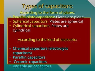
Types of capacitors
Types of capacitors:
:
According to the form of plates:
• Parallel plate capacitors:
Parallel plate capacitors: Plates are plane
Plates are plane
• Spherical capacitors:
Spherical capacitors: Plates are spherical
Plates are spherical
• Cylindrical capacitors:
Cylindrical capacitors: Plates are
Plates are
cylindrical
cylindrical
According to the kind of dielectric:
• Chemical capacitors (electrolytic
Chemical capacitors (electrolytic
capacitors)
capacitors)
• Paraffin capacitors
Paraffin capacitors
• Ceramic capacitors
Ceramic capacitors
• Variable air capacitors
Variable air capacitors
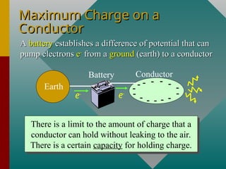
Maximum Charge on a
Maximum Charge on a
Conductor
Conductor
Earth
Battery Conductor
- - - - -
-
-
- -
- - - - -
e-
e-
A
A battery
battery establishes a difference of potential that can
establishes a difference of potential that can
pump electrons
pump electrons e
e-
-
from a
from a ground
ground (earth) to a conductor
(earth) to a conductor
There is a limit to the amount of charge that a
conductor can hold without leaking to the air.
There is a certain capacity for holding charge.
Capacitance
Capacitance
The capacitance C of a capacitor is defined
as the ratio of the charge Q on the plates to
the potential V produced between the
plates.
Earth
Battery Conductor
- - - - -
-
-
- -
- - - - -
e-
e-
Capacitance
:
; :
Q
C Units Coulombs per volt
V

Q, V
Capacitance in Farads
One
One farad (F)
farad (F) is the capacitance
is the capacitance C
C of a conductor that
of a conductor that
holds one coulomb of charge for each volt of potential.
(C)
; (F)
(V)
Q coulomb
C farad
V volt
 
Example:
Example: When 40
When 40 
C of charge are placed on a con-
C of charge are placed on a con-
ductor, the potential is 8 V. What is the capacitance?
40 C
8 V
Q
C
V

  C = 5 F
Capacitance and Shapes
The charge density on a surface is significantly
affected by the
affected by the curvature
curvature. The density of
. The density of
charge is greatest where the curvature is
greatest.
greatest.
+ + + +
+
++ + + +
++
+
+
+
+
+
+
+
+
+
+
+
+
+
+
+
+
+
Leakage (called corona discharge) often occurs
at sharp points where curvature r is greatest.
2
m
m
kQ
E
r

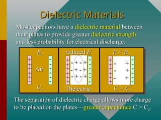
Dielectric Materials
Most capacitors have a
Most capacitors have a dielectric material
dielectric material between
between
their plates to provide greater
their plates to provide greater dielectric strength
dielectric strength
and less probability for electrical discharge.
The separation of dielectric charge allows more charge
to be placed on the plates—
to be placed on the plates—greater capacitance
greater capacitance C > C
C > Co
o.
.
+
+
+
+
+
+
-
-
-
-
-
-
Air
Air
C
Co
o
E
Eo
o
+
+
+
+
+
+
-
-
-
-
-
-
- +
- +
- +
- +
- +
- +
C > C
C > Co
o
E < E
E < Eo
o
+
+
+
+
+
+
-
-
-
-
-
-
- + - +
- + - +
- + - +
- + - +
- + - +
- + - +
Dielectric
Dielectric
reduced
reduced E
E
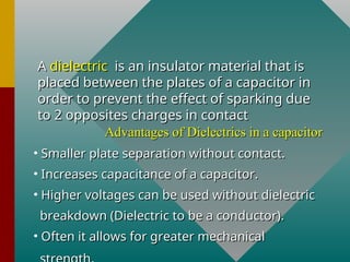
A
A dielectric
dielectric is an insulator material that is
is an insulator material that is
placed between the plates of a capacitor in
order to prevent the effect of sparking due
to 2 opposites charges in contact
Advantages of Dielectrics in a capacitor
• Smaller plate separation without contact.
Smaller plate separation without contact.
• Increases capacitance of a capacitor.
Increases capacitance of a capacitor.
• Higher voltages can be used without dielectric
Higher voltages can be used without dielectric
breakdown (Dielectric to be a conductor).
• Often it allows for greater mechanical
Often it allows for greater mechanical
Dielectric Strength
Dielectric Strength
The
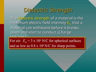
The dielectric strength
dielectric strength of a material is the
of a material is the
maximum electric field intensity
maximum electric field intensity E
Em
m that a
that a
material can withstand before it breaks
down and start to conduct (Charge
leakage.)
leakage.)
For air: Em = 3 x 10⁶
N/C for spherical surfaces
and as low as 0.8 x 10⁶
N/C for sharp points.
Dielectric Constant, K
The
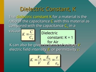
The dielectric constant K
dielectric constant K for a material is the
for a material is the
ratio of the capacitance
ratio of the capacitance C
C with this material as
with this material as
compared with the capacitance
compared with the capacitance C
Co
o in a
in a
vacuum.
vacuum.
Dielectric
constant: K = 1
for Air
0
C
K
C

K can also be given in terms of voltage
K can also be given in terms of voltage V
V,
,
electric field intensity
electric field intensity E
E, or permittivity
, or permittivity 
:
:
0 0
0
V E
K
V E


  
Insertion of Dielectric
+
+
+
+
+
+
Co Vo Eo 
+Q
-Q
+
+
+Q
-Q
Dielectric
Air
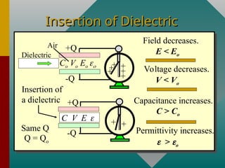
Permittivity increases.
> o
Capacitance increases.
C > Co
Voltage decreases.
V < Vo
Field decreases.
E < Eo
Insertion of
a dielectric
Same Q
Q = Qo
C V E 
Insertion of Dielectric
Let consider a capacitor of and capacitance in the
absence of a dielectric(When the capacitor is not connected to
the external circuit).
The potential difference measured is
If the dielectric is inserted between the plates, the voltage will
decrease by a factor K to a value V,
And
Qo
Co
Parallel Plate Capacitance
d
Area A
+Q
-Q
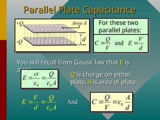
You will recall from Gauss’ law that
You will recall from Gauss’ law that E
E is
is
also:
also:
and
Q V
C E
V d
 
For these two
parallel plates:
0 0
Q
E
A

 
  Q
Q is charge on either
is charge on either
plate.
plate. A
A is area of plate.
is area of plate.
0
V Q
E
d A

  And
And 0
Q A
C
V d

 
Example 1.
Example 1. The plates of a parallel
The plates of a parallel
plate capacitor have an area of 0.4
m
m2
2
and are 3 mm apart in air. What is
the capacitance?
the capacitance?
3 mm
d
A
0.4 m2
0
Q A
C
V d

 
2
2
-12 2
C
Nm
(8.85 x 10 )(0.4 m )
(0.003 m)
C 
C = 1.18 nF
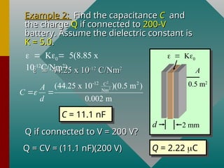
Example 2:
Example 2: Find the capacitance
Find the capacitance C
C and
and
the charge
the charge Q
Q if connected to
if connected to 200-V
200-V
battery. Assume the dielectric constant is
K = 5.0
K = 5.0.
.
2 mm
d
A
0.5 m2

5(8.85 x
10-12
C/Nm2
)

44.25 x 10
44.25 x 10⁻¹²
-12
C/Nm
C/Nm2
2
2
2
-12 2
C
Nm
(44.25 x 10 )(0.5 m )
0.002 m
A
C
d

 
C = 11.1 nF
Q if connected to V = 200 V?
Q = CV = (11.1 nF)(200 V)
Q = CV = (11.1 nF)(200 V) Q = 2.22 C
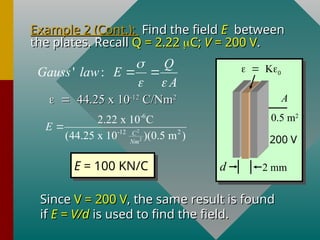
Example 2 (Cont.):
Example 2 (Cont.): Find the field
Find the field E
E between
between
the plates. Recall
the plates. Recall Q = 2.22
Q = 2.22 
C;
C; V
V = 200 V
= 200 V.
.

44.25 x 10
44.25 x 10⁻¹²
-12
C/Nm
C/Nm2
2
' :
Q
Gauss law E
A

 
 
2
2
-6
-12 2
2.22 x 10 C
(44.25 x 10 )(0.5 m )
C
Nm
E 
E = 100 KN/C
Since
Since V = 200 V
V = 200 V, the same result is found
, the same result is found
if
if E = V/d
E = V/d is used to find the field.
is used to find the field.
2 mm
d
A
0.5 m2

200 V
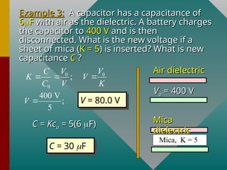
Example 3:
Example 3: A capacitor has a capacitance of
A capacitor has a capacitance of
6
6
F
F with air as the dielectric. A battery charges
with air as the dielectric. A battery charges
the capacitor to
the capacitor to 400 V
400 V and is then
and is then
disconnected. What is the new voltage if a
sheet of mica (
sheet of mica (K = 5
K = 5) is inserted? What is new
) is inserted? What is new
capacitance
capacitance C
C ?
?
0 0
0
;
V V
C
K V
C V K
  
400 V
;
5
V  V = 80.0 V
C = Kc
C = Kco
o =
= 5(6
5(6 
F)
F)
C = 30 F
V
Vo
o = 400 V
= 400 V
Mica, K = 5
Air dielectric
Air dielectric
Mica
Mica
dielectric
dielectric
Capacitance of an isolated
Sphere
Sphere
+Q
r
E and V at surface.
At surface of sphere:
2
;
kQ kQ
E V
r r
 
0
1
4
k


Recall:
Recall:
0
4
kQ Q
V
r r

 
And:
And: Capacitance:
Capacitance:
Q
C
V

0
4
Q Q
C
V Q r

  0
4
C r


Capacitance, C
Example 1:
Example 1: What is the capacitance
What is the capacitance
of a metal sphere of radius 8 cm?
r = 0.08 m
Capacitance, C
+Q
r
Capacitance: C = 4
Capacitance: C = 4

r
r
2
-12 C
N m
4 (8.85 x 10 )(0.08 m)
C  

C = 8.90 x 10⁻¹²
F
Note: The capacitance depends only on physical para-
meters (the radius r) and is not determined by either
charge or potential. This is true for all capacitors.
(8.90 pF)(400 V)
Q 
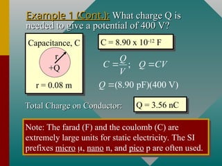
Q = 3.56 nC
Total Charge on Conductor:
Example 1 (Cont.):
Example 1 (Cont.): What charge Q is
What charge Q is
needed to give a potential of 400 V?
r = 0.08 m
Capacitance, C
+Q
r
C = 8.90 x 10⁻¹²
F
;
Q
C Q CV
V
 
Note: The farad (F) and the coulomb (C) are
extremely large units for static electricity. The SI
prefixes micro , nano n, and pico p are often used.
Capacitance of a cylindrical
capacitor
capacitor
Applications of Capacitors
+
+
+
+
+
+
+
-
-
-
-
-
-- A
Variable
Capacitor
Changing
Area
0
A
C
d


d
Changing d
Microphone
Q
V
C

A
A microphone
microphone converts sound waves into an
converts sound waves into an
electrical signal (varying voltage) by changing
electrical signal (varying voltage) by changing d
d.
.
The
The tuner
tuner in a radio is a
in a radio is a variable capacitor
variable capacitor. The changing
. The changing
area
area A
A alters capacitance until desired signal is obtained.
alters capacitance until desired signal is obtained.
Energy of Charged
Energy of Charged
Capacitor
Capacitor
The
The potential energy
potential energy U
U of a
of a
charged capacitor is equal to the
work (
work (qV
qV) required to charge the
) required to charge the
capacitor.
capacitor.
If we consider the average
potential difference from 0 to V
potential difference from 0 to Vf
f to
to
be
be V/2
V/2:
:
Work = Q(V/2) = ½QV
2
2
1 1
2 2
; ;
2
Q
U QV U CV U
C
  
Example 4:
Example 4: In Ex-2, we found capacitance
In Ex-2, we found capacitance
to be
to be 11.1 nF
11.1 nF, the voltage
, the voltage 200 V
200 V, and the
, and the
charge
charge 2.22
2.22 
C
C. Find the potential energy
. Find the potential energy
U
U.
.
2
1
2 (11.1 nF)(200 V)
U 
U = 222 J
2
1
2
U CV

Verify your answer from
the other formulas for P.E.
2
1
2 ;
2
Q
U QV U
C
 
C = 11.1 nF
200 V
Q = 2.22 C
U = ?
Capacitor
Capacitor
of Example
of Example
5
5.
.
Energy Density for
Energy Density for
Capacitor
Capacitor
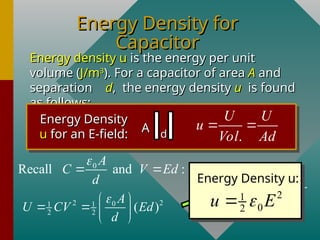
Energy density u
Energy density u is the energy per unit
is the energy per unit
volume (
volume (J/m
J/m3
3
). For a capacitor of area
). For a capacitor of area A
A and
and
separation
separation d
d, the energy density
, the energy density u
u is found
is found
as follows:
as follows:
Energy Density
Energy Density
u
u for an E-field:
for an E-field: A
A d
d .
U U
u
Vol Ad
 
2 2
0
1 1
2 2 ( )
A
U CV Ed
d

 
   
 
0
Recall and :
A
C V Ed
d

  2
1
0
2 AdE
U
u
Ad Ad

 
Energy Density u:
2
1
0
2
u E


Summary of Formulas
Summary of Formulas
(C)
; (F)
(V)
Q coulomb
C farad
V volt
 
0
4
C r


0
Q A
C K
V d

 
0 0
0 0
V E
C
K
C V E


   
2
2
1 1
2 2
; ;
2
Q
U QV U CV U
C
  
2
1
0
2
u E

