Download to read offline
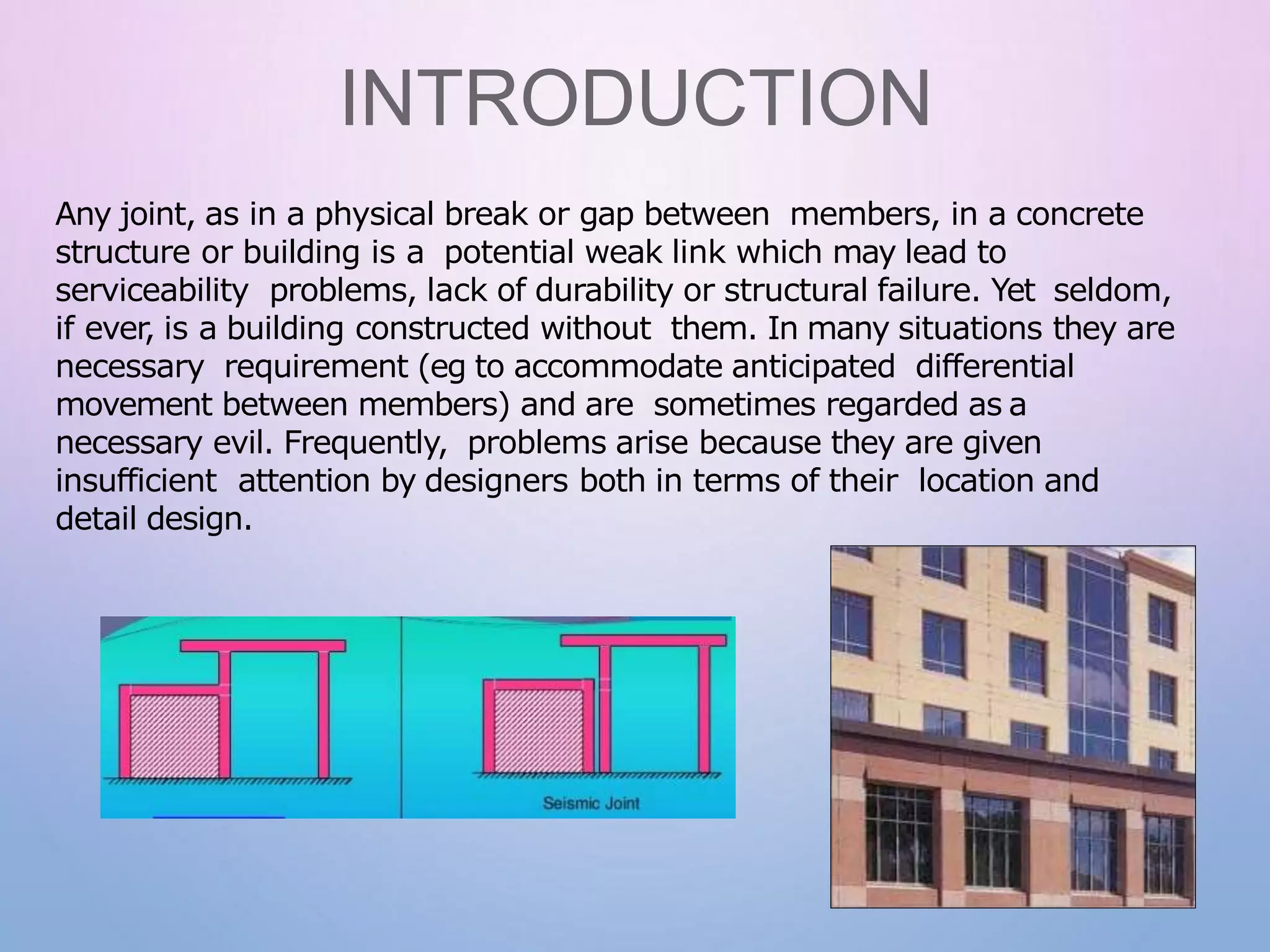
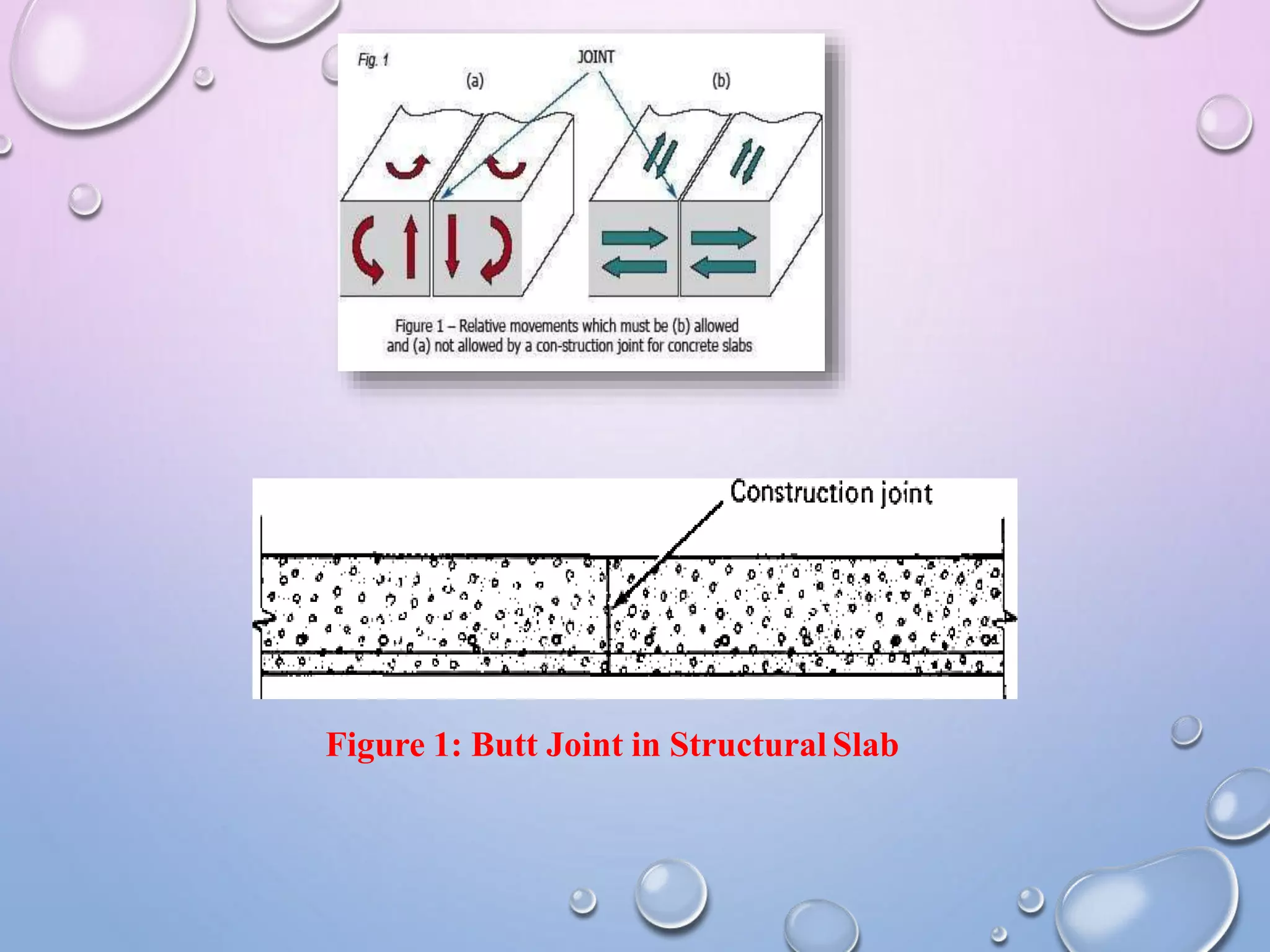
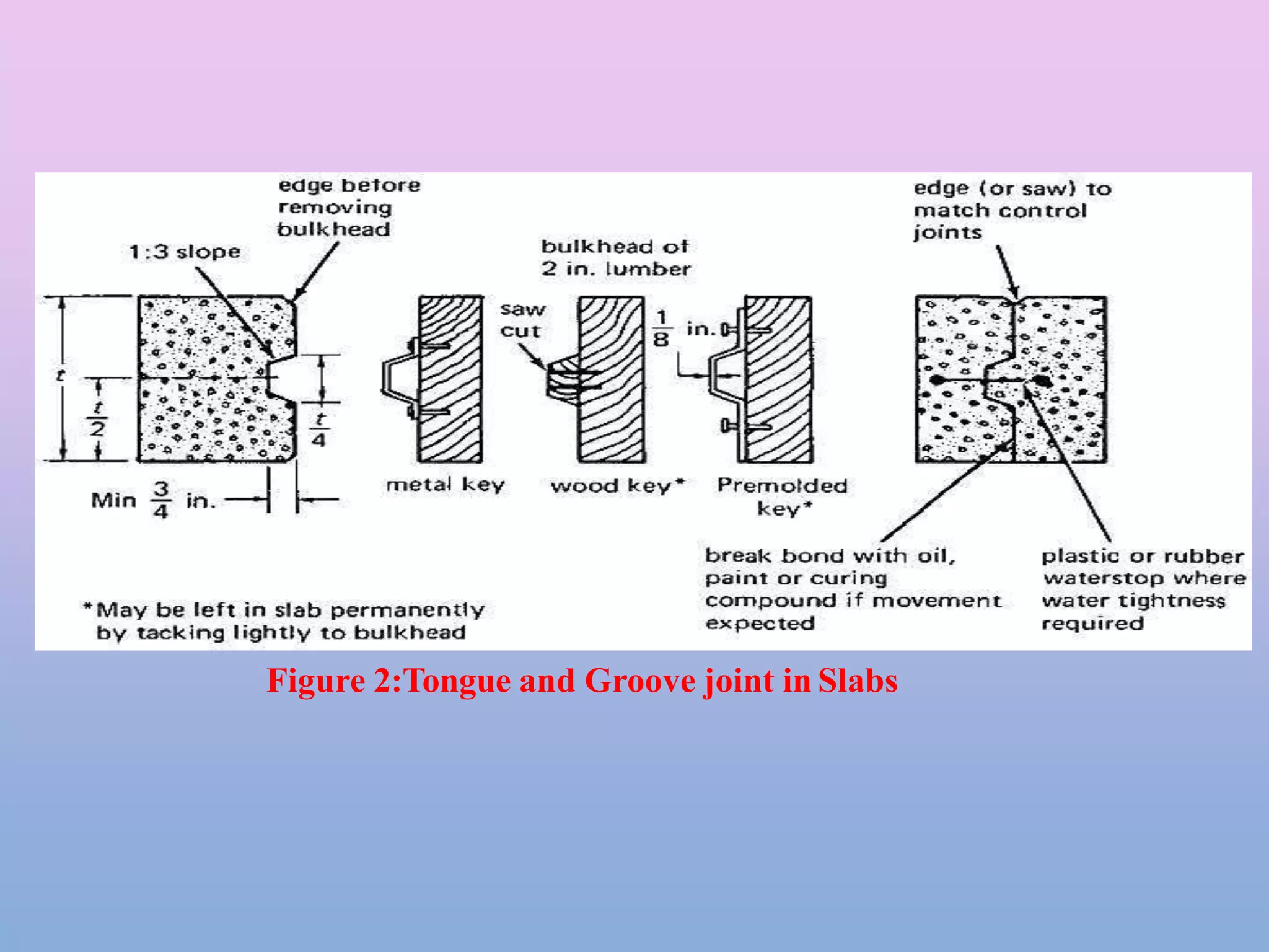
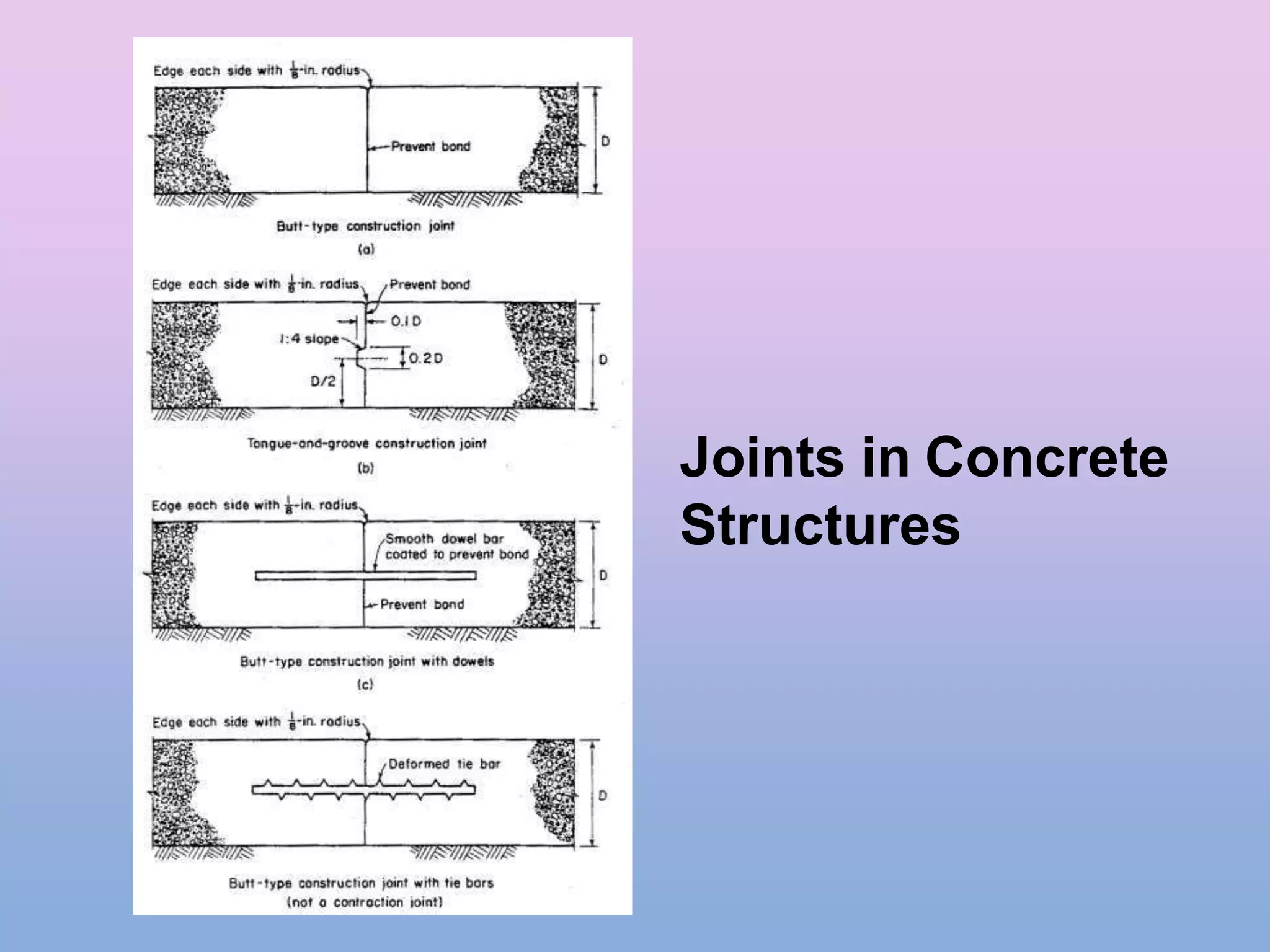


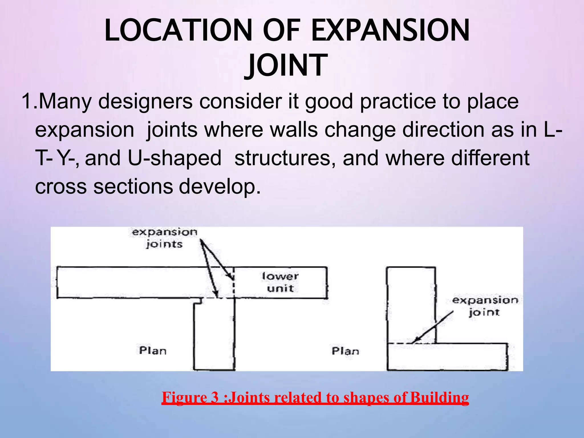


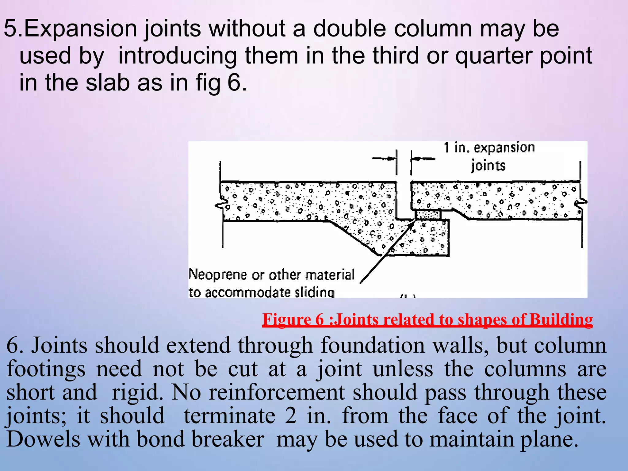

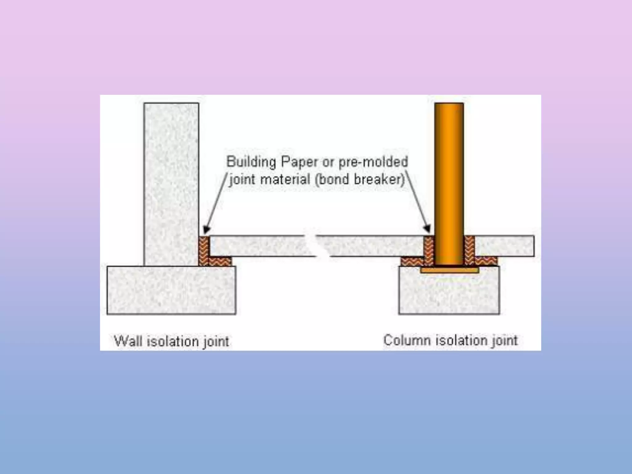


This document discusses different types of joints used in concrete structures and buildings. It describes construction joints, which define placements of concrete slabs and allow for movement. Expansion joints prevent cracking from temperature changes. Contraction joints create planes of weakness to control cracking. Isolation joints separate new and existing concrete that may expand differently. The document provides details on the purpose, design, and proper installation of each type of joint to allow for structural movement while maintaining integrity.


