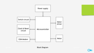
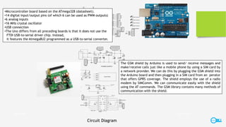
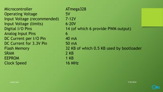
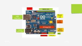
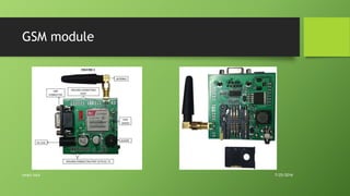
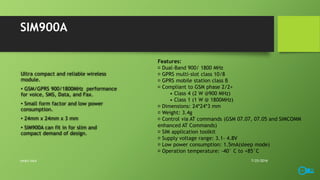
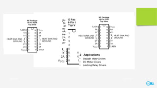
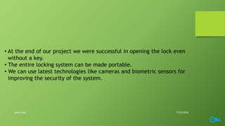
MINIPROJECT 2016
UNIVERSITY COLLEGE OF ENGINEERING, KARIAVATTOM
Department of Electronics and Communication
7/25/2016smart lock
smart lock
S6, ECE
Anwar C John
Ashik S R
Sachin Lal D
Suman S Raj
Project Description
Objective
• A portable lock which can also be
unlocked via SMS.
• The system automatically locks and
unlocks as soon as the lock receives a
predefined message from the user.
• Works both manually and
automatically.
7/25/2016smart lock
Procedure/Methodology
• The project intends to interface the microcontroller with the GSM
modem and lock/unlock the lock by sending the predefined
messages from the mobile to the controlling unit.
• The project uses the GSM technology and Embedded Systems to
design this application.
• The main objective of this project is to design a system that
continuously checks the messages if any, received from the user
mobile and change the status of the lock as per the message
received from the mobile.
7/25/2016smart lock
Block Diagram 7/25/2016smart lock
Microcontroller
Power supply
Motor
driver
Motor
Switch circuit
Clock & Reset
circuit
GSM Modem
•Microcontroller board based on the ATmega328 (datasheet).
•14 digital input/output pins (of which 6 can be used as PWM outputs)
•6 analog inputs
•16 MHz crystal oscillator
•USB connection
•The Uno differs from all preceding boards is that it does not use the
FTDI USB-to-serial driver chip. Instead,
it features the Atmega8U2 programmed as a USB-to-serial converter.
The GSM shield by Arduino is used to send/ receive messages and
make/receive calls just like a mobile phone by using a SIM card by
a network provider. We can do this by plugging the GSM shield into
the Arduino board and then plugging in a SIM card from an perator
that offers GPRS coverage. The shield employs the use of a radio
modem by SIMComm. We can communicate easily with the shield
using the AT commands. The GSM library contains many methods of
communication with the shield.
Circuit Diagram
7/25/2016smart lock
Motor Driver Circuit
7/25/2016smart lock
ATmega 328
Technical specification
7/25/2016smart lock
Microcontroller ATmega328
Operating Voltage 5V
Input Voltage (recommended) 7-12V
Input Voltage (limits) 6-20V
Digital I/O Pins 14 (of which 6 provide PWM output)
Analog Input Pins 6
DC Current per I/O Pin 40 mA
DC Current for 3.3V Pin 50 mA
Flash Memory 32 KB of which 0.5 KB used by bootloader
SRAM 2 KB
EEPROM 1 KB
Clock Speed 16 MHz
7/25/2016smart lock
7/25/2016smart lock
digital pinsTX/RX
USB
interface
Power
Led
ICSP
Header
Reset
Button
ATmega328
Power pins Analog pins
External
power supply
I2C
GSM SHIELD
GSM SHIELD USING SIMCOMM
(SIM900A)
7/25/2016smart lock
GSM module
7/25/2016smart lock
SIM900A
Ultra compact and reliable wireless
module.
• GSM/GPRS 900/1800MHz performance
for voice, SMS, Data, and Fax.
• Small form factor and low power
consumption.
• 24mm x 24mm x 3 mm
• SIM900A can fit in for slim and
compact demand of design.
7/25/2016smart lock
Features:
Dual-Band 900/ 1800 MHz
GPRS multi-slot class 10/8
GPRS mobile station class B
Compliant to GSM phase 2/2+
• Class 4 (2 W @900 MHz)
• Class 1 (1 W @ 1800MHz)
Dimensions: 24*24*3 mm
Weight: 3.4g
Control via AT commands (GSM 07.07, 07.05 and SIMCOMM
enhanced AT Commands)
SIM application toolkit
Supply voltage range: 3.1- 4.8V
Low power consumption: 1.5mA(sleep mode)
Operation temperature: -40° C to +85°C
L293x Quadruple Half-H Drivers
7/25/2016smart lock
7/25/2016smart lock
Geared DC motors
7/25/2016smart lock
Geared DC motors can be defined as an extension of DC motor
which already had its Insight details demystified here.
A geared DC Motor has a gear assembly attached to the motor.
The speed of motor is counted in terms of rotations of the
shaft per minute and is termed as RPM .The gear assembly helps
in increasing the torque and reducing the speed. Using the correct
combination of gears in a gear motor, its speed can be reduced to
any desirable figure.
DC Motor
7/25/2016smart lock
μA7800 SERIES
POSITIVE-VOLTAGE REGULATORS
7/25/2016smart lock
Description
This series of fixed-voltage integrated-circuit voltage regulators is designed for a wide range of applications.
These applications include on-card regulation for elimination of noise and distribution problems associated with
single-point regulation. Each of these regulators can deliver up to 1.5 A of output current. The internal
current-limiting and thermal-shutdown features of these regulators essentially make them immune to overload.
In addition to use as fixed-voltage regulators, these devices can be used with external components to obtain
adjustable output voltages and currents, and also can be used as the power-pass element in precision
regulators.
7/25/2016smart lock
Arduino PCB & components layout
7/25/2016smart lock
Project Summary
• At the end of our project we were successful in opening the lock even
without a key.
• The entire locking system can be made portable.
• We can use latest technologies like cameras and biometric sensors for
improving the security of the system.
7/25/2016smart lock
Future scope
•We can use latest technologies like cameras and biometric sensors for
improving the security of the system.
•The lock can be interfaced with a PC application and hence the SIM can also be
accessed through it.
•The key can be replaced by speech recognition.
7/25/2016smart lock
Conclusion
• The work was successful. It is evident that the use of mobile
phones with the right circuitry can be used to operate a locking
system.
• In this project we used an Arduino board. Arduino boards are cost
efficient and they are user friendly and hence can be easily
programmed.
• The entire locking system is portable.
• The future of this project is vast and endless.
7/25/2016smart lock
7/25/2016smart lock
thank you
credits
team members
anwar c john
ashik s r
sachin lal d
suman s raj
Guidance
Ansil Shafi

Smart Lock

  • 1.
    MINIPROJECT 2016 UNIVERSITY COLLEGEOF ENGINEERING, KARIAVATTOM Department of Electronics and Communication 7/25/2016smart lock
  • 2.
    smart lock S6, ECE AnwarC John Ashik S R Sachin Lal D Suman S Raj
  • 3.
    Project Description Objective • Aportable lock which can also be unlocked via SMS. • The system automatically locks and unlocks as soon as the lock receives a predefined message from the user. • Works both manually and automatically. 7/25/2016smart lock
  • 4.
    Procedure/Methodology • The projectintends to interface the microcontroller with the GSM modem and lock/unlock the lock by sending the predefined messages from the mobile to the controlling unit. • The project uses the GSM technology and Embedded Systems to design this application. • The main objective of this project is to design a system that continuously checks the messages if any, received from the user mobile and change the status of the lock as per the message received from the mobile. 7/25/2016smart lock
  • 5.
    Block Diagram 7/25/2016smartlock Microcontroller Power supply Motor driver Motor Switch circuit Clock & Reset circuit GSM Modem
  • 6.
    •Microcontroller board basedon the ATmega328 (datasheet). •14 digital input/output pins (of which 6 can be used as PWM outputs) •6 analog inputs •16 MHz crystal oscillator •USB connection •The Uno differs from all preceding boards is that it does not use the FTDI USB-to-serial driver chip. Instead, it features the Atmega8U2 programmed as a USB-to-serial converter. The GSM shield by Arduino is used to send/ receive messages and make/receive calls just like a mobile phone by using a SIM card by a network provider. We can do this by plugging the GSM shield into the Arduino board and then plugging in a SIM card from an perator that offers GPRS coverage. The shield employs the use of a radio modem by SIMComm. We can communicate easily with the shield using the AT commands. The GSM library contains many methods of communication with the shield. Circuit Diagram 7/25/2016smart lock
  • 7.
  • 8.
  • 9.
    Microcontroller ATmega328 Operating Voltage5V Input Voltage (recommended) 7-12V Input Voltage (limits) 6-20V Digital I/O Pins 14 (of which 6 provide PWM output) Analog Input Pins 6 DC Current per I/O Pin 40 mA DC Current for 3.3V Pin 50 mA Flash Memory 32 KB of which 0.5 KB used by bootloader SRAM 2 KB EEPROM 1 KB Clock Speed 16 MHz 7/25/2016smart lock
  • 10.
  • 11.
    GSM SHIELD GSM SHIELDUSING SIMCOMM (SIM900A) 7/25/2016smart lock
  • 12.
  • 13.
    SIM900A Ultra compact andreliable wireless module. • GSM/GPRS 900/1800MHz performance for voice, SMS, Data, and Fax. • Small form factor and low power consumption. • 24mm x 24mm x 3 mm • SIM900A can fit in for slim and compact demand of design. 7/25/2016smart lock Features: Dual-Band 900/ 1800 MHz GPRS multi-slot class 10/8 GPRS mobile station class B Compliant to GSM phase 2/2+ • Class 4 (2 W @900 MHz) • Class 1 (1 W @ 1800MHz) Dimensions: 24*24*3 mm Weight: 3.4g Control via AT commands (GSM 07.07, 07.05 and SIMCOMM enhanced AT Commands) SIM application toolkit Supply voltage range: 3.1- 4.8V Low power consumption: 1.5mA(sleep mode) Operation temperature: -40° C to +85°C
  • 14.
    L293x Quadruple Half-HDrivers 7/25/2016smart lock
  • 15.
  • 16.
  • 17.
    Geared DC motorscan be defined as an extension of DC motor which already had its Insight details demystified here. A geared DC Motor has a gear assembly attached to the motor. The speed of motor is counted in terms of rotations of the shaft per minute and is termed as RPM .The gear assembly helps in increasing the torque and reducing the speed. Using the correct combination of gears in a gear motor, its speed can be reduced to any desirable figure. DC Motor 7/25/2016smart lock
  • 18.
  • 19.
    Description This series offixed-voltage integrated-circuit voltage regulators is designed for a wide range of applications. These applications include on-card regulation for elimination of noise and distribution problems associated with single-point regulation. Each of these regulators can deliver up to 1.5 A of output current. The internal current-limiting and thermal-shutdown features of these regulators essentially make them immune to overload. In addition to use as fixed-voltage regulators, these devices can be used with external components to obtain adjustable output voltages and currents, and also can be used as the power-pass element in precision regulators. 7/25/2016smart lock
  • 20.
    Arduino PCB &components layout 7/25/2016smart lock
  • 21.
  • 22.
    • At theend of our project we were successful in opening the lock even without a key. • The entire locking system can be made portable. • We can use latest technologies like cameras and biometric sensors for improving the security of the system. 7/25/2016smart lock
  • 23.
    Future scope •We canuse latest technologies like cameras and biometric sensors for improving the security of the system. •The lock can be interfaced with a PC application and hence the SIM can also be accessed through it. •The key can be replaced by speech recognition. 7/25/2016smart lock
  • 24.
    Conclusion • The workwas successful. It is evident that the use of mobile phones with the right circuitry can be used to operate a locking system. • In this project we used an Arduino board. Arduino boards are cost efficient and they are user friendly and hence can be easily programmed. • The entire locking system is portable. • The future of this project is vast and endless. 7/25/2016smart lock
  • 25.
    7/25/2016smart lock thank you credits teammembers anwar c john ashik s r sachin lal d suman s raj Guidance Ansil Shafi

Editor's Notes