This document is the Indian Railway Standard Code of Practice for plain, reinforced and prestressed concrete for general bridge construction from 1997. It provides definitions for terminology used, specifies materials and workmanship for concrete, reinforcement and prestressing tendons. It defines loads, load combinations and requirements for limit state design. It provides recommendations for the design and construction of plain concrete, reinforced concrete and prestressed concrete bridges. The document covers topics such as concrete mix design, formwork, reinforcement, transportation and curing of concrete, prestressing, precast construction, and load testing.
![IRS Concrete Bridge Code..1997
V-38
Effective pumping range is upto 300m
horizontally and 90m vertically.
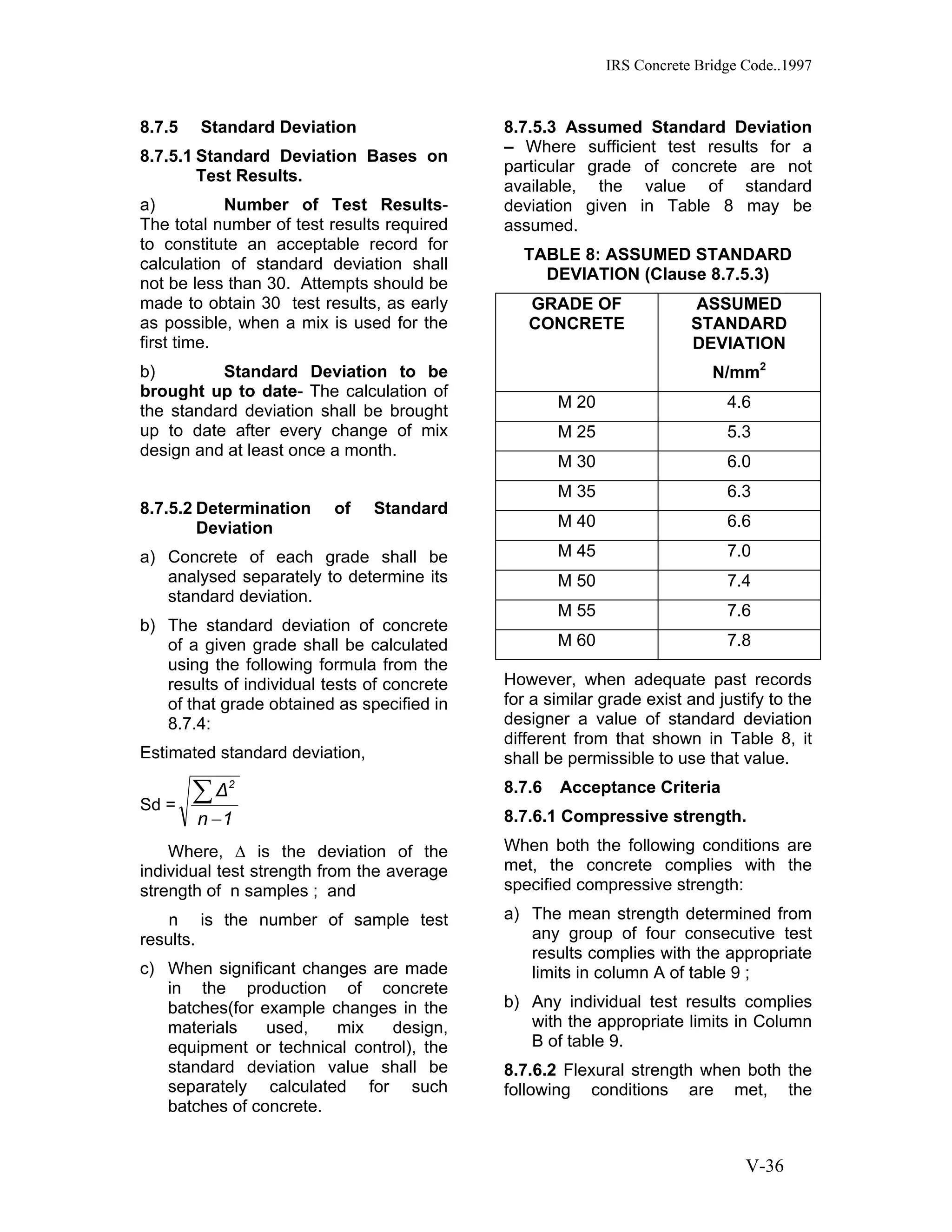
8.9.3 Proportioning Pumpable
Concrete
8.9.3.1 Basic Consideration- More
emphasis on quality control is essential
to the proportioning and use of a
dependable pump mix. Concrete mixes
for pumping must be plastic. Particular
attention must be given to the mortar
and to the amounts and sizes of coarse
aggregates.
8.9.3.2 The maximum size of angular
coarse aggregate is limited to one-third
of smallest inside diameter of the hose
or pipe. Provisions should be made for
elimination of oversized particles in the
concrete by finish screening or by
careful selection of aggregates.
8.9.4 Pumping Concrete – Proper
planning of concrete supply, pump
locations, line layout, placing sequences
and the entire pumping operation will
result in saving of cost and time. The
pump should be placed as near the
placing area as practicable and the
entire surrounding area must have
adequate bearing strength. Lines from
the pump to the placing area should be
laid out with a minimum of bends. The
pipe line shall be rigidly supported.
8.9.4.1 While pumping downward 15m
or more, it is desirable to provide an air
release valve at the middle of the top
bend to prevent vacuum or air build-up.
When pumping upward, it is desirable to
have a valve near the pump to prevent
reverse flow.
9 GROUTING OF PRE-STRESSING
CABLES.
9.1 A recommended practice for
grouting of cables is given at
Appendix D.
10. LIMIT STATE REQUIREMENTS
10.1 General – In the method of design
based on limit state concept, the
structure shall be designed so as to
ensure an adequate degree of safety
and serviceability. The acceptable limit
for each of the safety and serviceability
requirements is called a ‘Limit State’.
For this purpose the limit states of 10.2
and 10.3 shall be considered. The
usual approach will be to design on the
basis of the limit state expected to be
most critical and then to check that the
remaining limit states will not be
reached and that all other requirements
will be met.
Consideration of other factors, such as,
deflection, fatigue and durability, will
need to be made as referred to in 10.4.
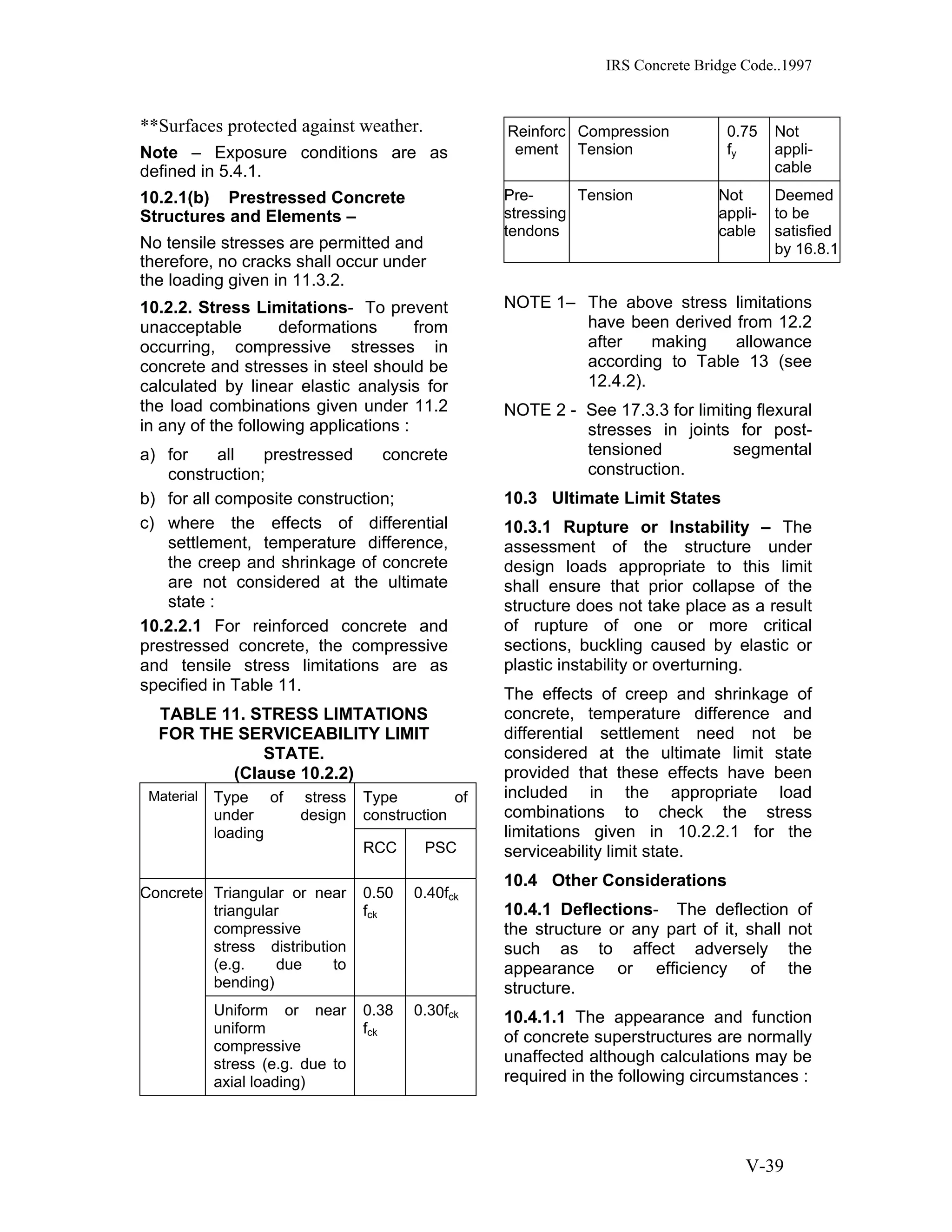
10.2 Serviceability Limit States –
The design shall be such that the
structure will not suffer local damage
which would shorten its intended life or
incur expensive maintenance costs. In
particular, calculated crack widths shall
not exceed those permitted in 10.2.1.
10.2.1 Cracking- Cracking of concrete
shall not adversely affect the
appearance of durability of the structure.
The engineer should satisfy himself that
any cracking will not be excessive,
having regard to the requirements of the
particular structure and the conditions of
exposure. In the absence of special
investigations, the following limit shall be
adopted.
10.2.1(a) Reinforced concrete –
Design crack widths, as calculated in
accordance with 15.9.8.2, shall not
exceed the values given in Table 10
under the loading given in 11.3.2 :
TABLE 10: DESIGN CRACK WIDTHS
[Cl. 10.2.1 (a) ]
Environment Design crack width
in mm
Mild 0.20
Moderate 0.20
Severe 0.10*
0.20**
Very severe 0.10*
0.20**
Extreme 0.10*
0.20**
*Surfaces exposed to weather.](https://image.slidesharecdn.com/irsconcretebridgecode-151106083454-lva1-app6891/75/Irs-concrete-bridge-code-43-2048.jpg)


![IRS Concrete Bridge Code..1997
V-95
16.8.4.3 If the tendons are prevented
from bonding to the concrete near the
ends of the units by the use of sleeves
or tape, the transmission lengths shall
be taken from the ends of the de-
bonded portions.
16.8.5 End Blocks - The end block
(also known as the anchor block or end
zone) is defined as the highly stressed
zone of concrete around the termination
points of a pre or post tensioned
prestressing tendon. It extends from the
points of application of prestress (i.e. the
end of the bonded part of the tendon in
pre tensioned construction or the
anchorage in post-tensioned
construction) to that section of the
member at which linear distribution of
stress is assumed to occur over the
whole cross-section.
16.8.5.1 The following aspects of
design shall be considered in assessing
the strength of end blocks:
(a) bursting forces around individual
anchorages;
(b) overall equilibrium of the end
block;
(c) spalling of the concrete form the
loaded face around anchorages.
16.8.5.1.1 In considering each of these
aspects, particular attention shall be
given to factor such as the following:
(1) shape, dimensions and position
of anchor plates relative to the
cross-section of the end block:
(2) the magnitude of the
prestressing forces and the
sequence of prestressing;
(3) shape of the end block relative to
the general shape of the
member;
(4) layout of anchorages including
asymmetry group effects and
edge distances;
(5) influence of the support reaction;
(6) forces due to curved or divergent
tendons.]
16.8.5.2 The following
recommendations are appropriate to a
circular, square or rectangular anchor
plate, symmetrically positioned on the
end face of a square or rectangular post
tensioned member, the
recommendations are followed by some
guidance on other aspects.
16.8.5.2.1 The bursting tensile forces
in the end blocks, or end regions of
bonded post-tensioned members, shall
be assessed on the basis of the tendon
jacking load. For temporarily unbonded
members, the bursting tensile forces
shall be assessed on the basis of the
tendon jacking load or the load in the
tendon at the ultimate limit state,
calculated using 16.2.4.3 whichever is
the greater.
16.8.5.2.2 The bursting tensile force ,
Fbst existing in an individual square end
block loaded by a symmetrically placed
square anchorage or bearing plate, may
be derived from Table 27,
Where
Yo is half the side of end block;
Ypo is half the side of loaded area;
Pk is the load in the tendon
assessed in accordance with the
preceding paragraph.
Fbst is the bursting tensile force.
This force, Fbst, will be distributed in
a region extending from 0.2Yo to 2Yo
from the loaded face of the end block.
Reinforcement provided to sustain the
bursting tensile force may be assumed
to be acting at its design strength
(0.87fy) except that the stress shall be
limited to a value corresponding to a
strain of 0.001 when the concrete cover
to the reinforcement is less than 50mm.
16.8.5.2.3 In the rectangular end block,
the bursting tensile forces in the two](https://image.slidesharecdn.com/irsconcretebridgecode-151106083454-lva1-app6891/75/Irs-concrete-bridge-code-100-2048.jpg)


