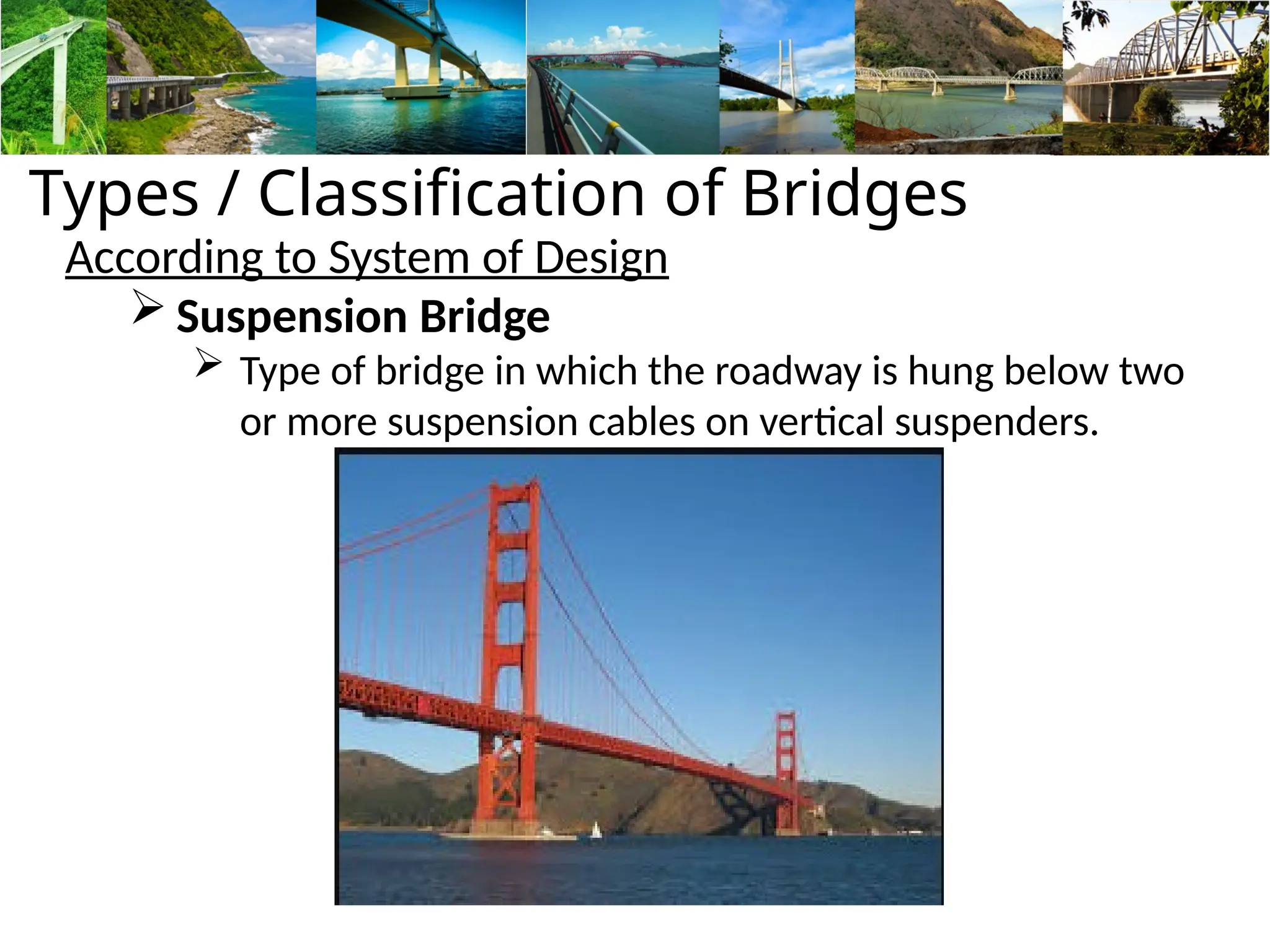
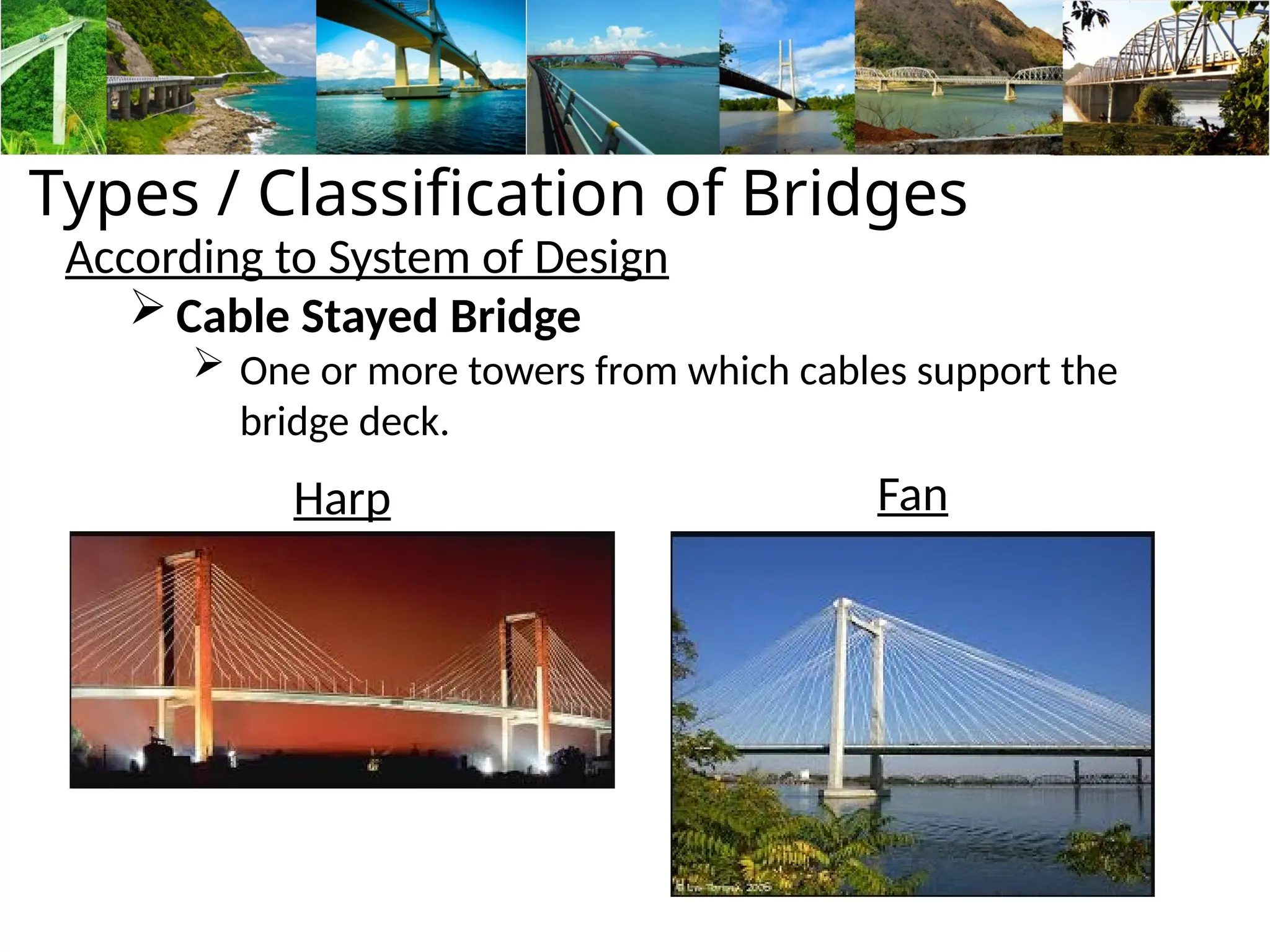
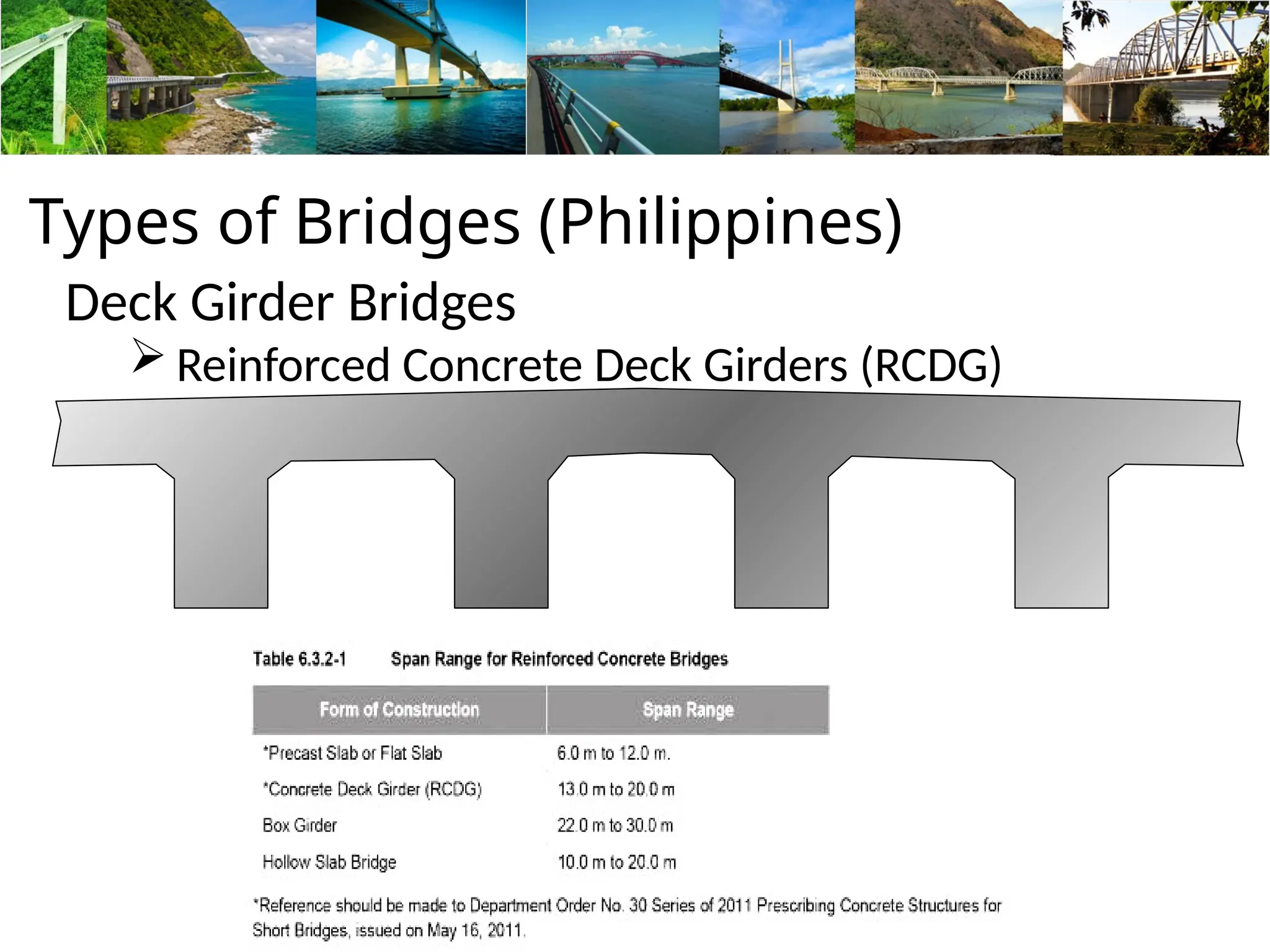
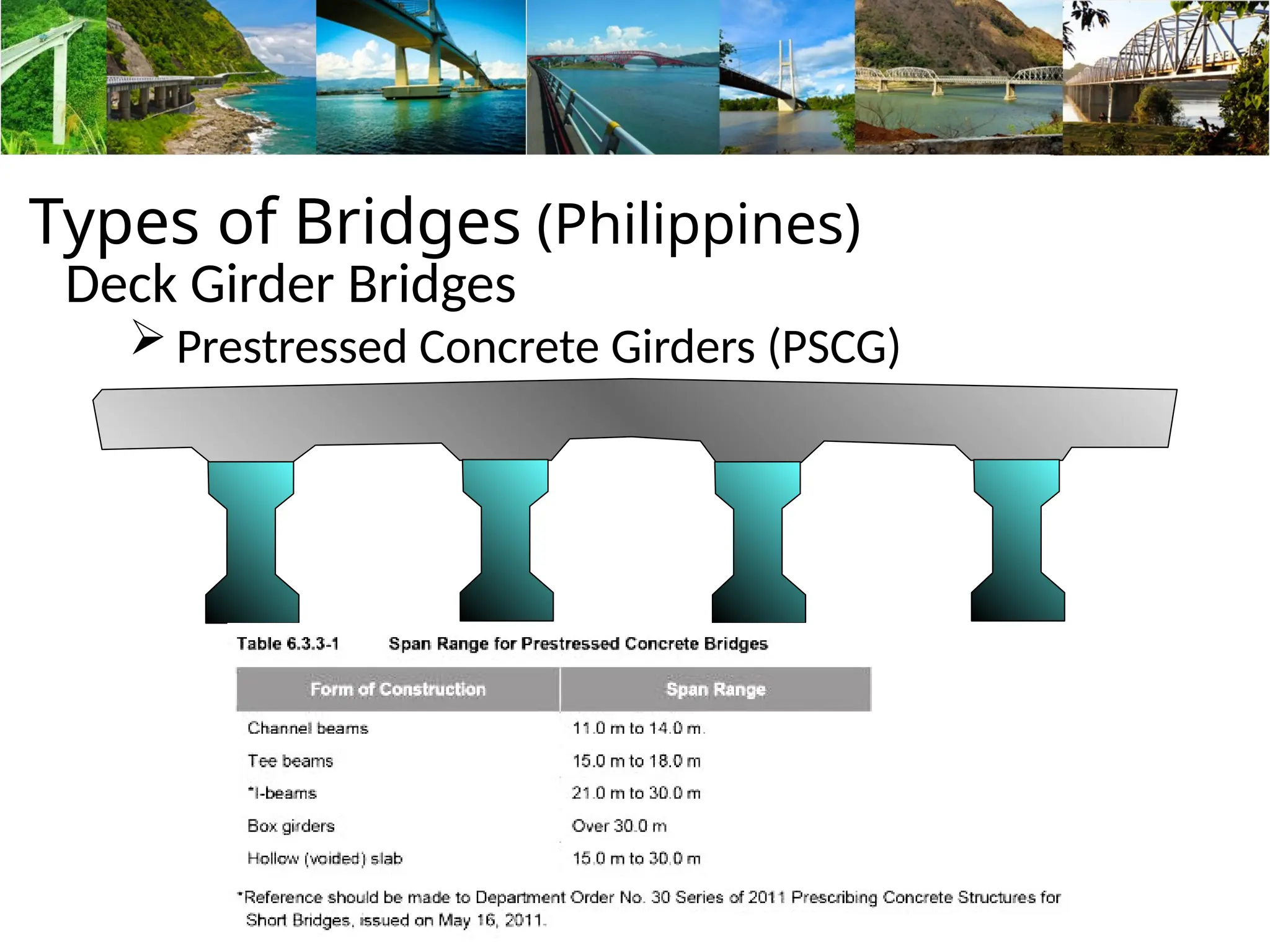
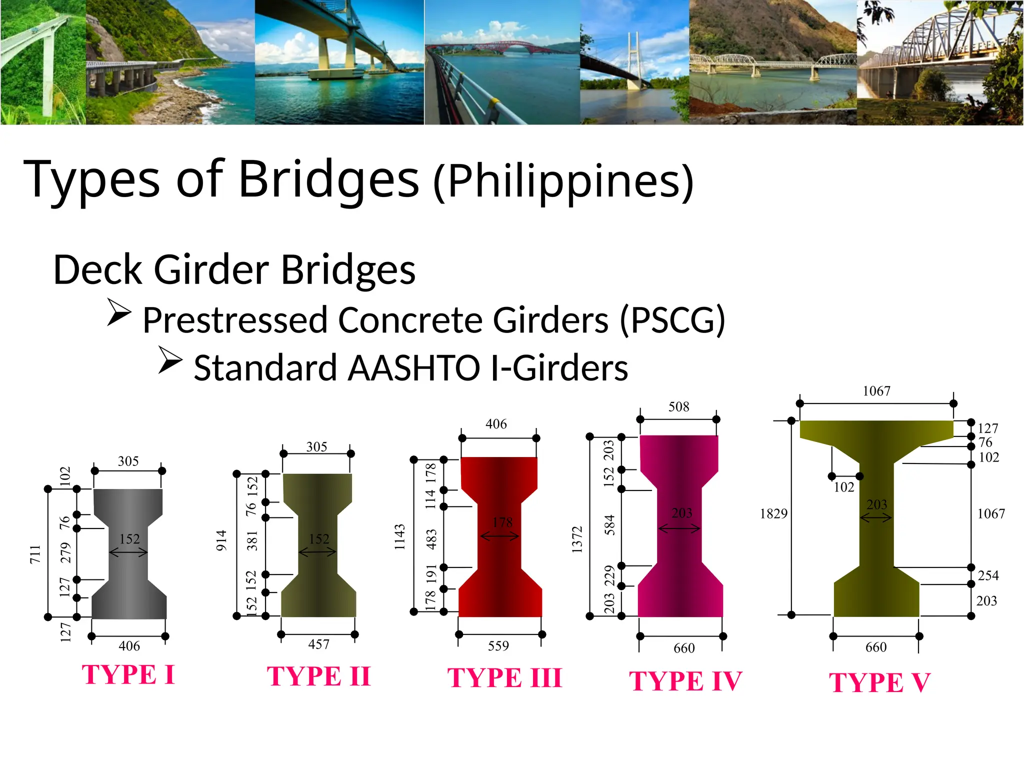
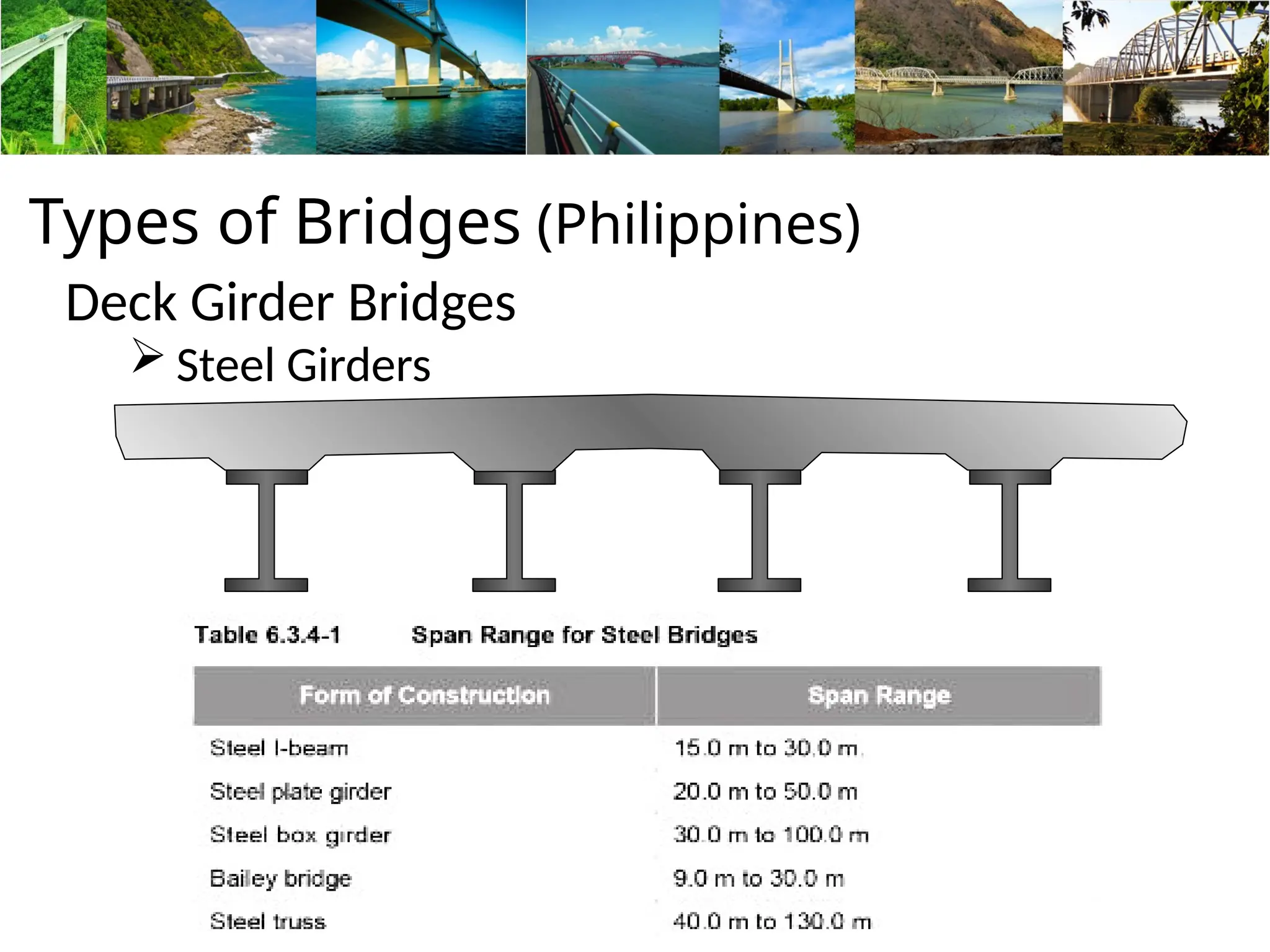
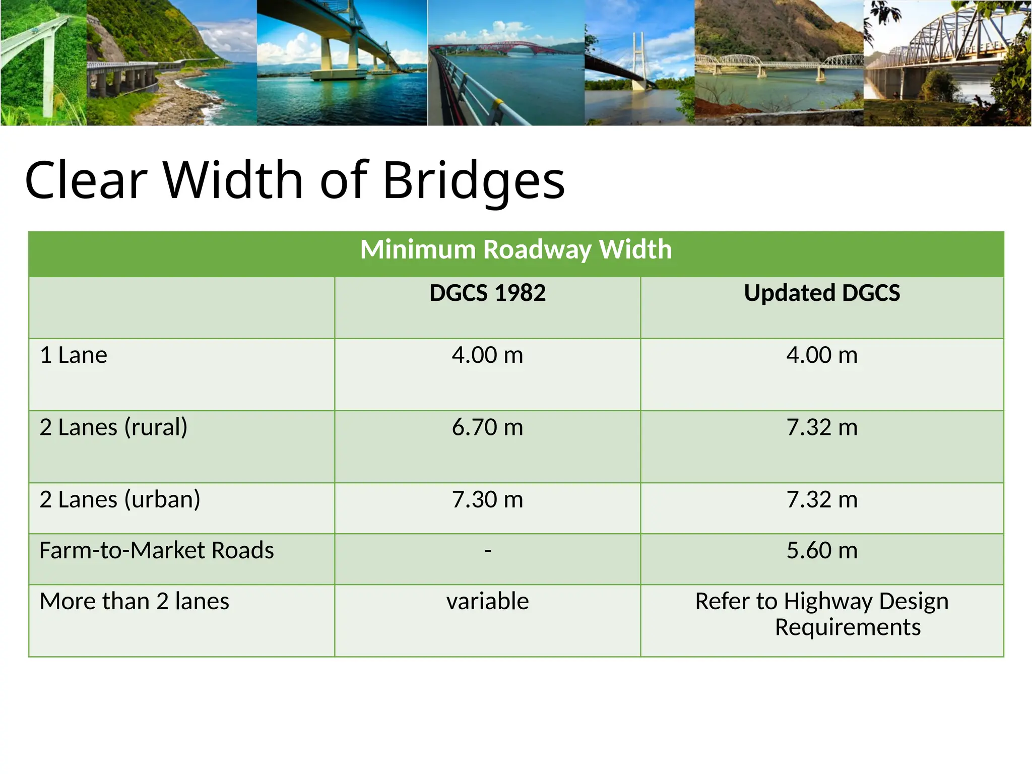
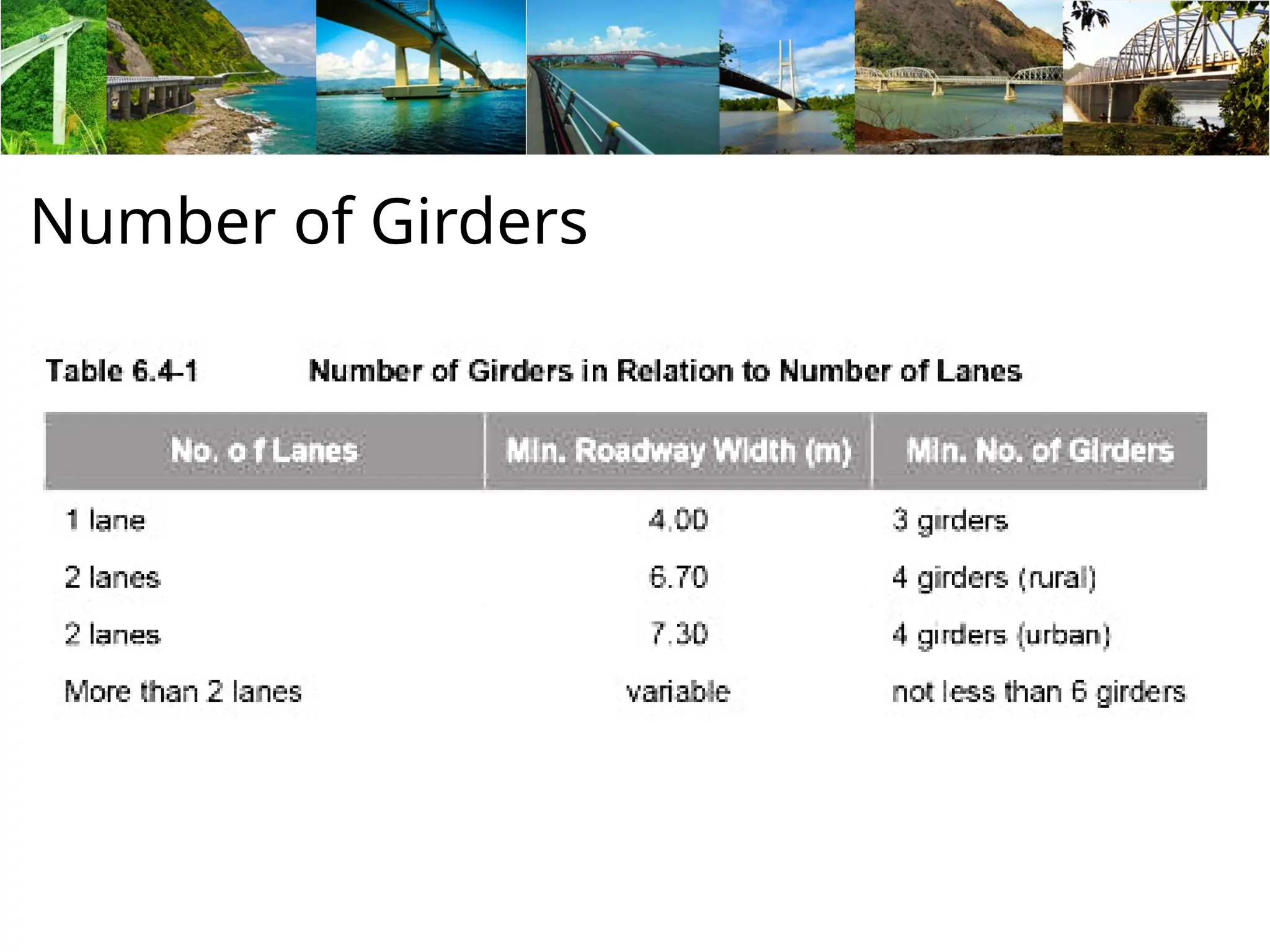
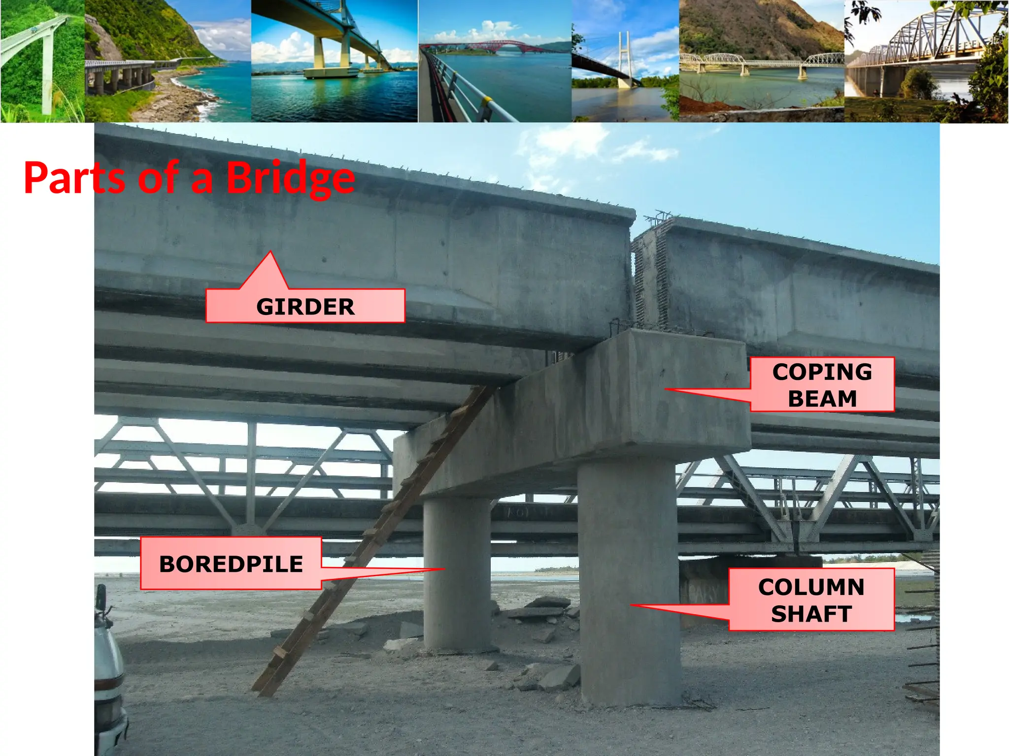
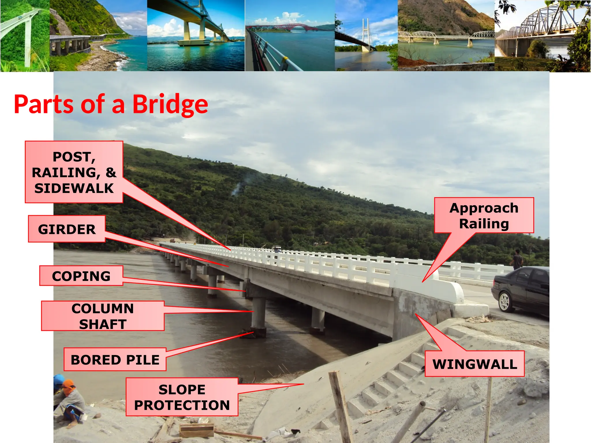
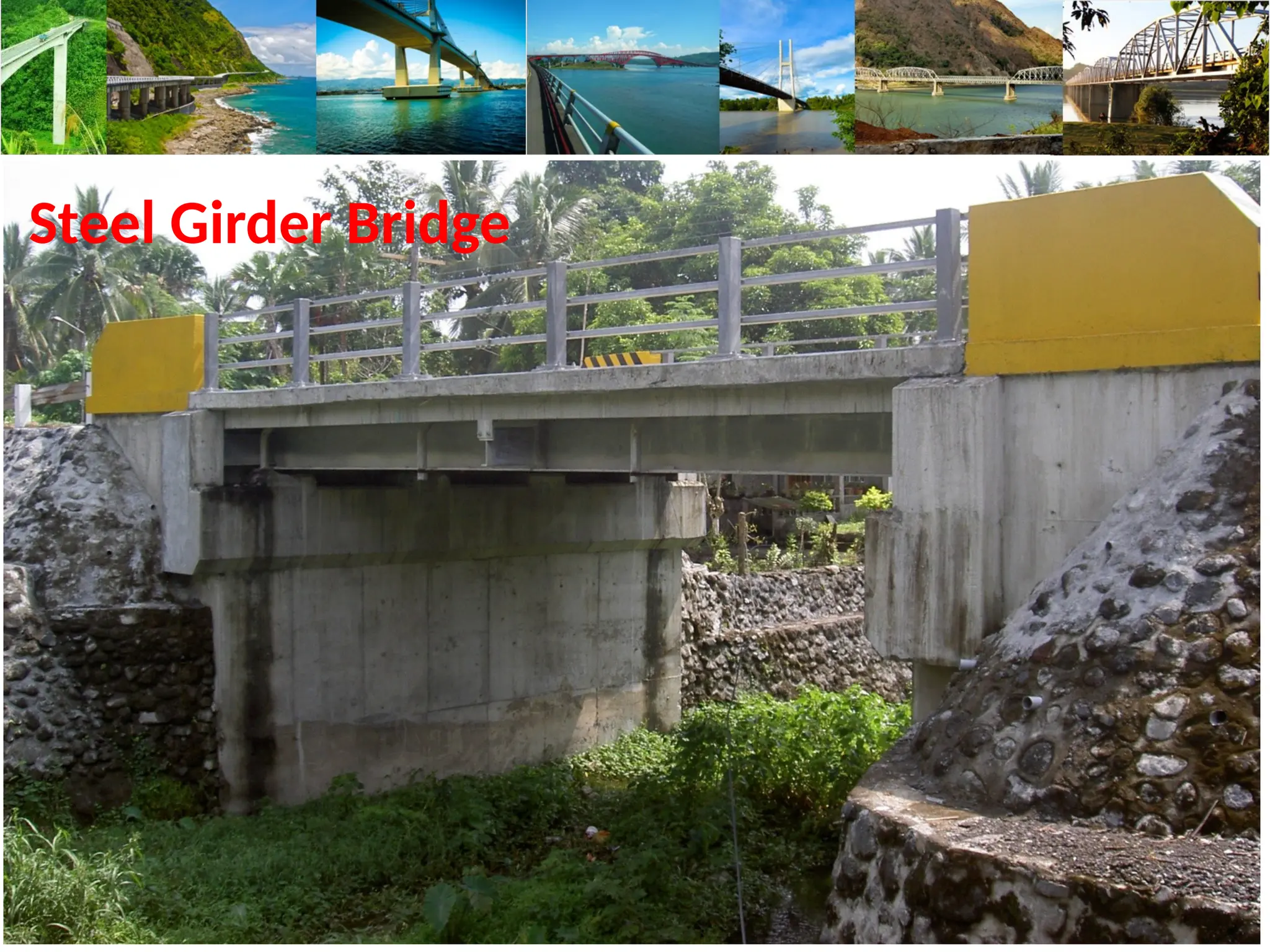
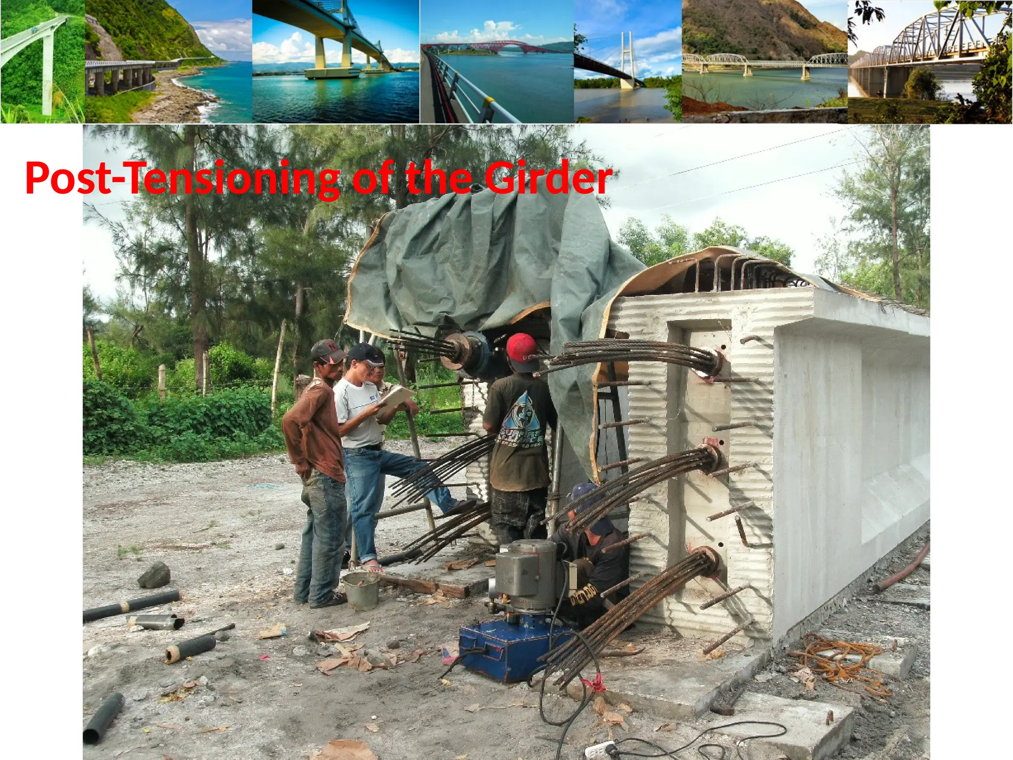
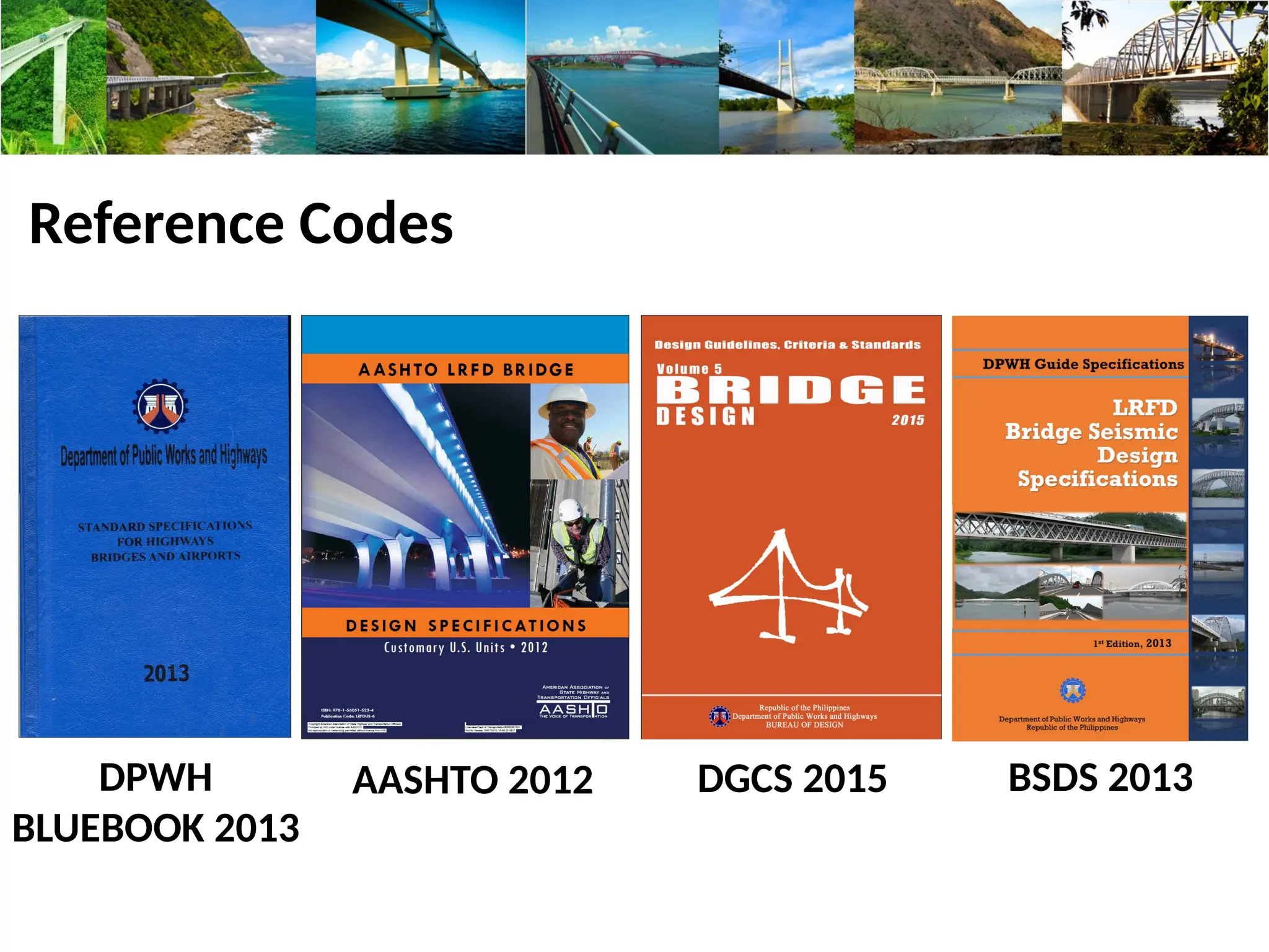
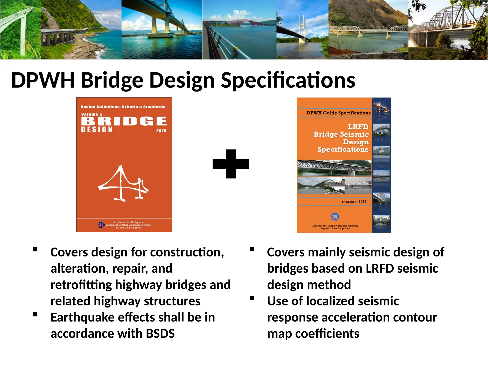
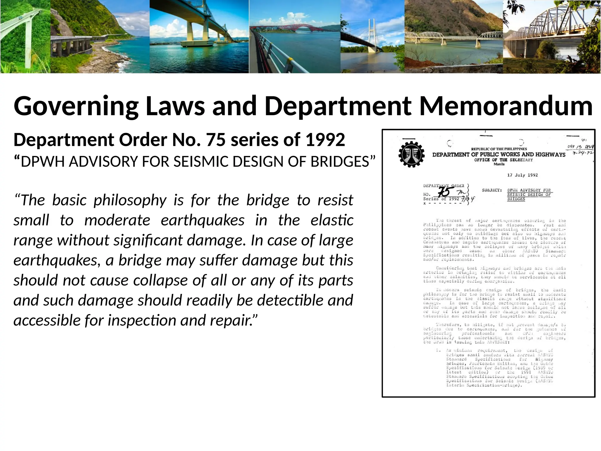
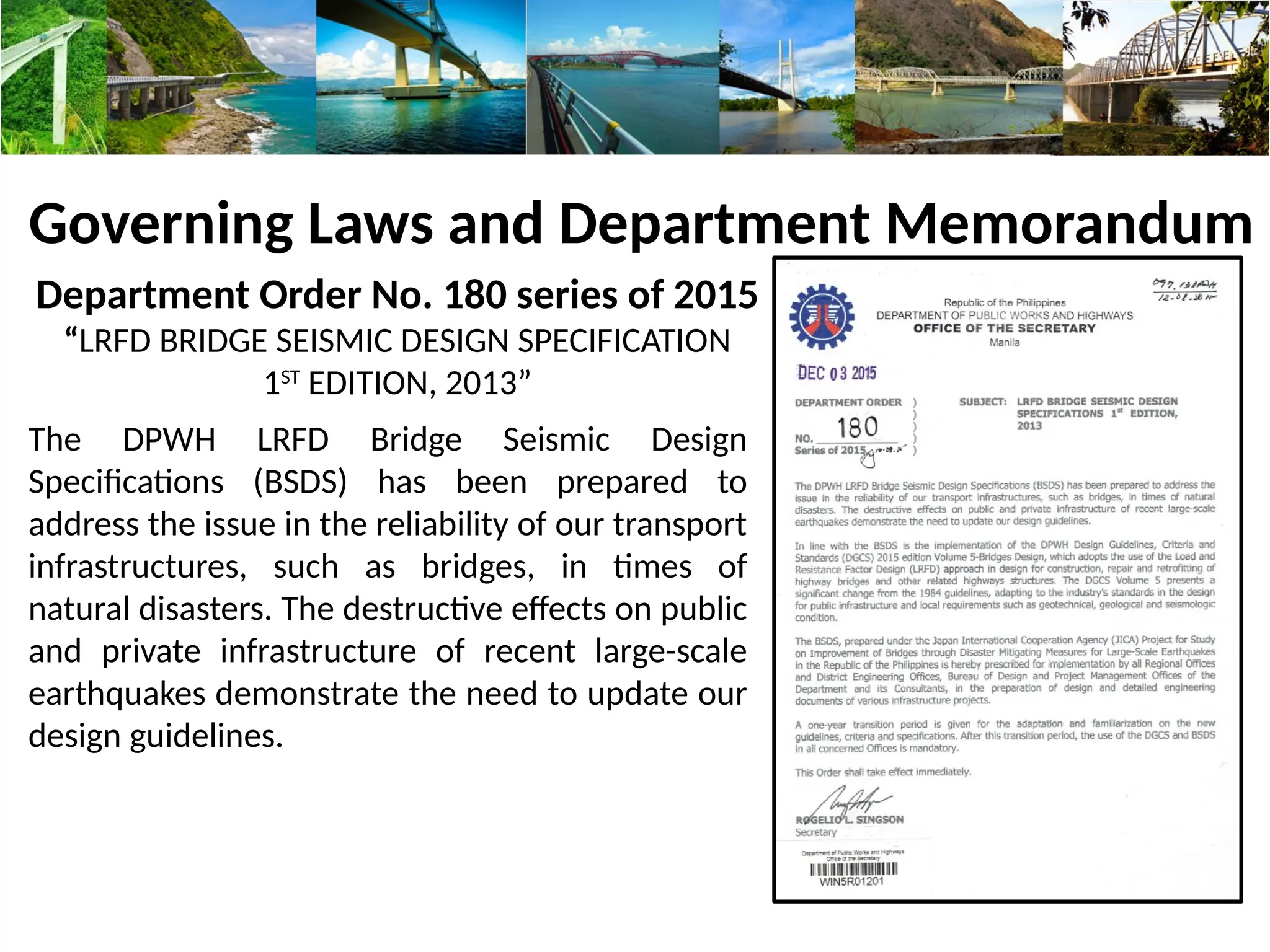
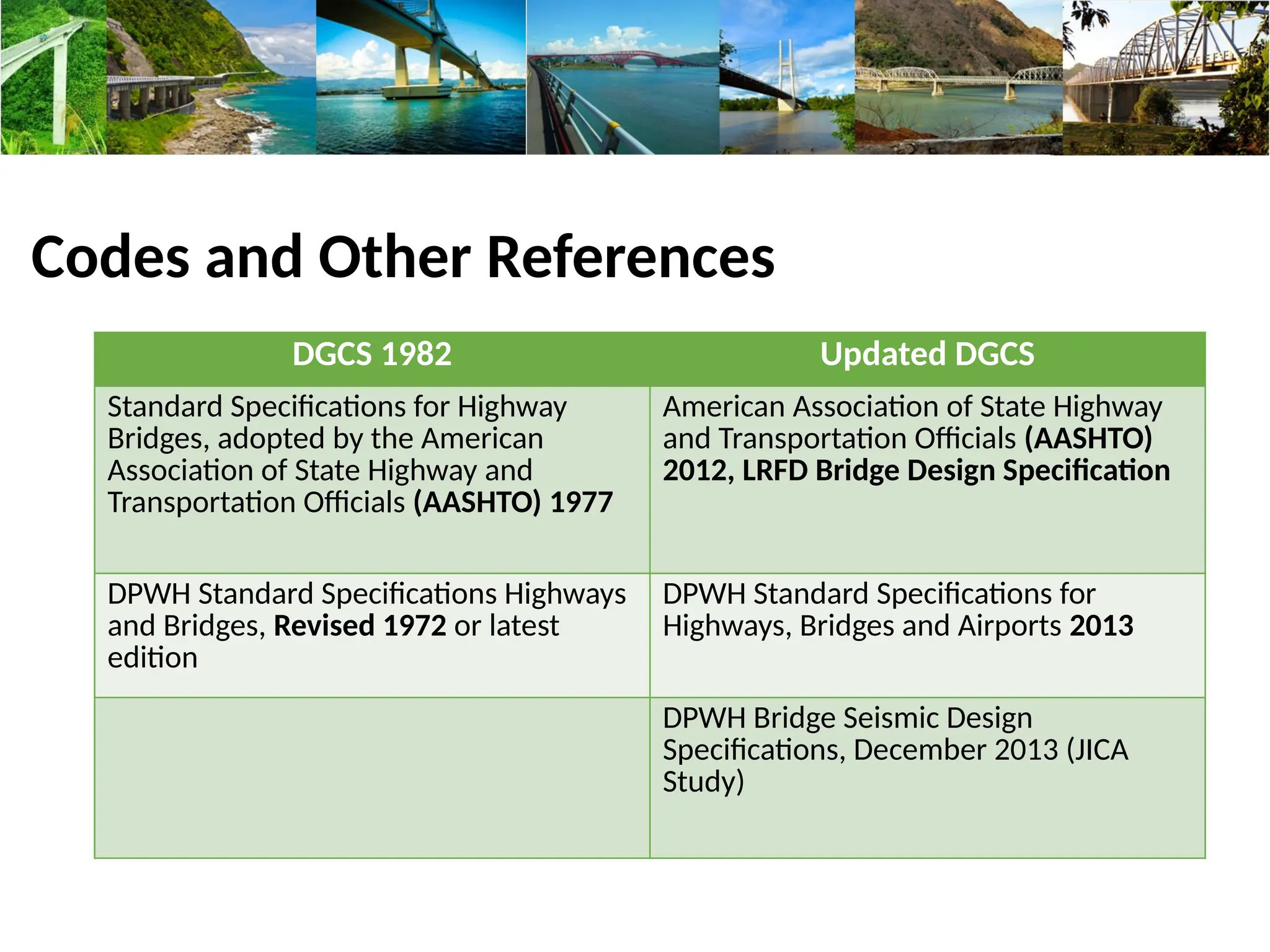
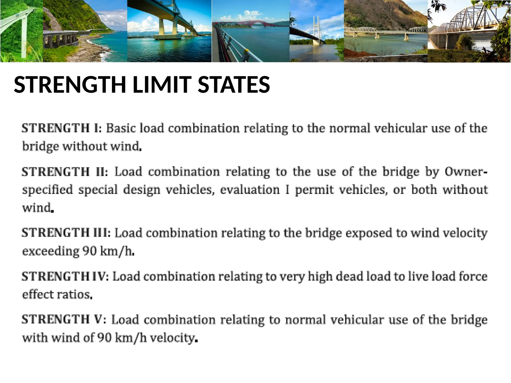
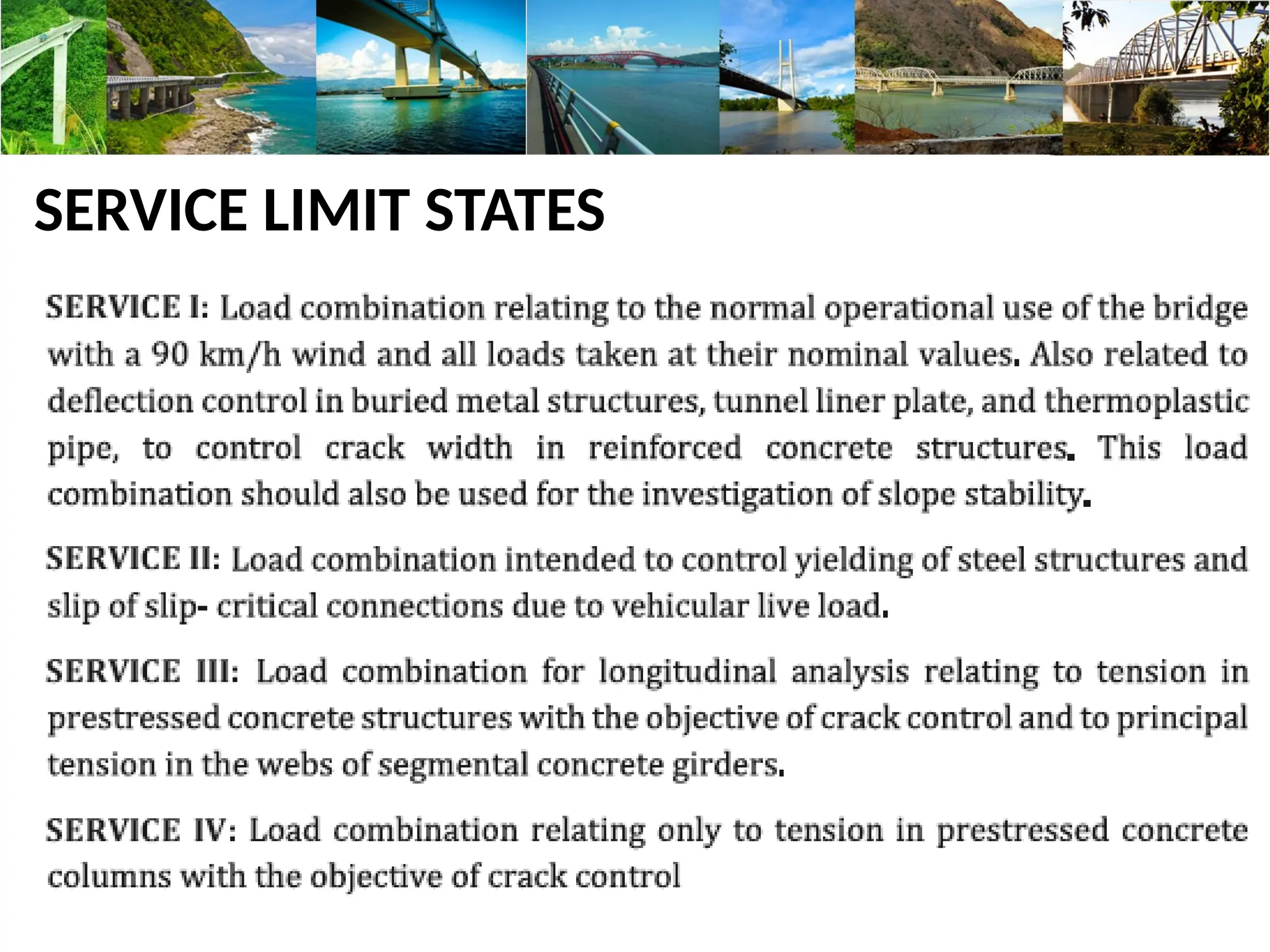
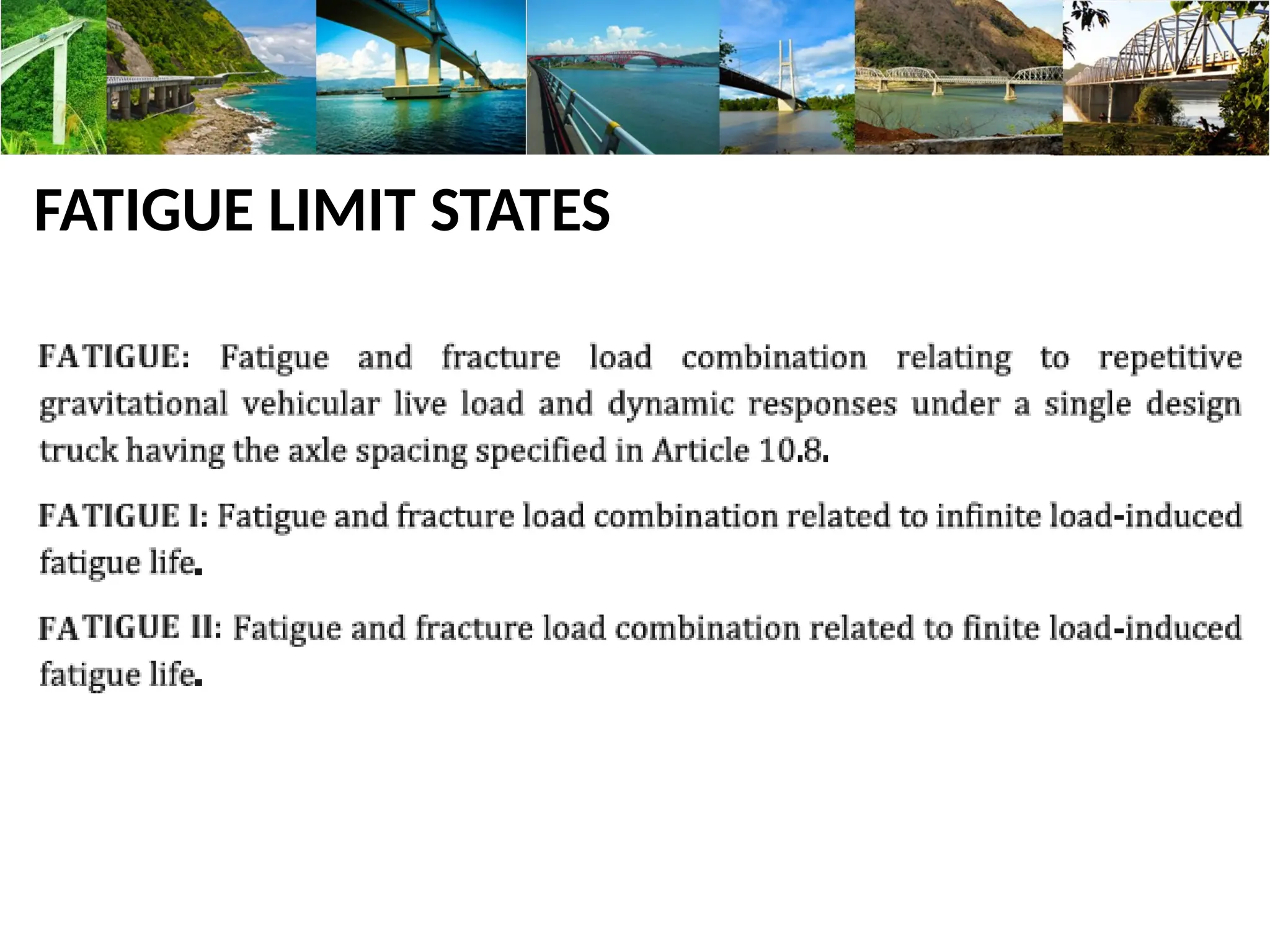
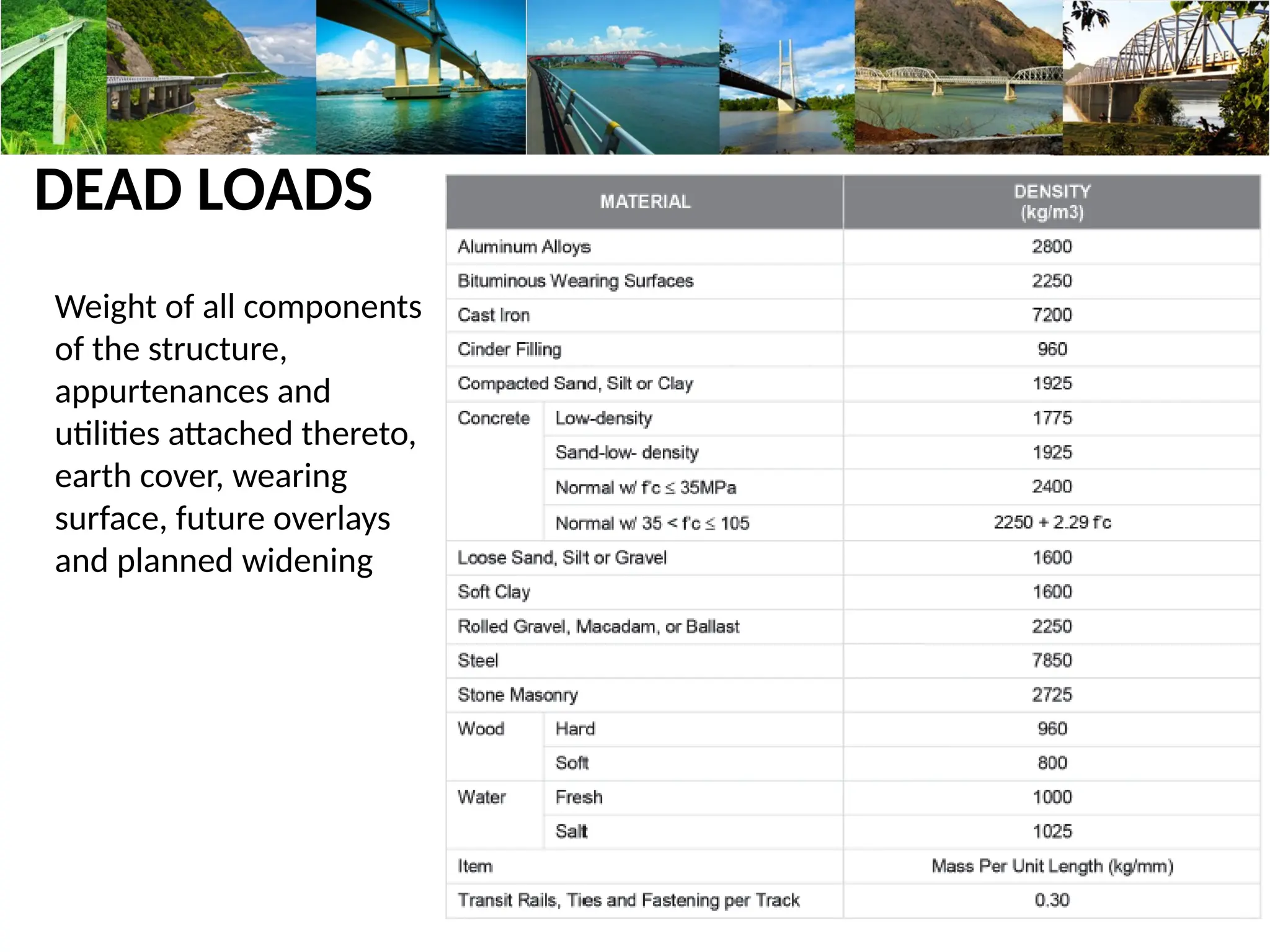
BRIDGE DESIGN
PARAMETERS
SEMINAR: CONSTRUCTION METHODS AND TECHNIQUES FOR BRIDGES
DATE : September 10, 2019
DPWH Standard Specifications on Bridges
Outline:
Part 1. Introduction to Bridge Engineering
Part 2. Design Philosophies & Parameters
Part 1: Introduction to
Bridge Engineering
Sample General Elevation Plan
Sample General Plan
Sample General Elevation Plan
What is a Bridge?
A structure built to span physical obstacle such as a body of water,
valley, or road, for the purpose of providing passage over the
obstacle.
A structure carrying a road over a waterway, road or other
feature, with a clear span over 3.00 meters along the centerline
between the inside faces of supports.
A bridge may have an independent deck supported on separate
piers and abutments, or may have a deck constructed integral
with supports
(Ref:DGCS 2015)
Bridge Superstructure
Bridge Alignment
 A Normal Bridge is a structure where the superstructure is perpendicular to
the substructure.
Bridge Superstructure
Bridge Alignment
 A Skew Bridge is a structure where the superstructure is not perpendicular
to the substructure. The skew angle is the deviation of the substructure
centerlines and reference lines from the perpendicular lines to the bridge
axis.
θ
Bridge Superstructure
Bridge Alignment
 A Curved Bridge is a structure or portion of the structure that follows a
horizontal or vertical curve alignment.
Types / Classification of Bridges
According to Materials used for Main Structural Members
 Timber Bridge
 Concrete Bridge
Types / Classification of Bridges
According to Materials used for Main Structural Members
 Prestressed Concrete Bridge
 Steel Bridge
Types / Classification of Bridges
According to Usage
 Temporary – a bridge with a short life span due to
deterioration and/or design limitations, including:
 Timber trestle bridge that normally requires
members to be replaced after three years.
 Bailey bridges not designed in accordance with a
Bridge Code and subject to early fatigue failure,
subject to the number of load cycles.
Types / Classification of Bridges
According to Usage
 Permanent
 A bridge with a design life of fifty years and usually
of concrete or steel construction.
Types / Classification of Bridges
According to System of Design
 Simple Spans
 Consists of separate beams for each span, supported on
bearings that allow rotation of the girders at each end
under loads.
 Continuous Spans
 Superstructure is made continuous over one or more
supports.
Types / Classification of Bridges
According to System of Design
 Cantilever Bridge
 Bridge built using structures that project horizontally into
space, supported at only one end.
Types / Classification of Bridges
According to System of Design
 Arch Bridge
 Bridge with abutments at each end and a supporting
structure shaped as a curved arch.
Types / Classification of Bridges
According to System of Design
 Suspension Bridge
 Type of bridge in which the roadway is hung below two
or more suspension cables on vertical suspenders.
Types / Classification of Bridges
According to System of Design
 Cable Stayed Bridge
 One or more towers from which cables support the
bridge deck.
Harp Fan
Types of Bridges (Philippines)
Deck Girder Bridges
 Reinforced Concrete Deck Girders (RCDG)
Types of Bridges (Philippines)
Deck Girder Bridges
 Prestressed Concrete Girders (PSCG)
Types of Bridges (Philippines)
Deck Girder Bridges
 Prestressed Concrete Girders (PSCG)
 Standard AASHTO I-Girders
305
102
76
279
127
127
711
406
152
305
152
76
381
152
152
914
152
457
406
178
114
483
191
178
1143
559
178
508
203
152
584
229
203
1372
660
203
1067
127
76
102
1067
254
203
203
1829
102
660
TYPE I TYPE II TYPE III TYPE IV TYPE V
Types of Bridges (Philippines)
Deck Girder Bridges
 Steel Girders
Clear Width of Bridges
Minimum Roadway Width
DGCS 1982 Updated DGCS
1 Lane 4.00 m 4.00 m
2 Lanes (rural) 6.70 m 7.32 m
2 Lanes (urban) 7.30 m 7.32 m
Farm-to-Market Roads - 5.60 m
More than 2 lanes variable Refer to Highway Design
Requirements
Number of Girders
Parts of a Bridge
1. Superstructure
1. Deck Slab
2. Girder
3. Diaphragm (End & Intermediate)
4. Post & Railing
5. Sidewalk
6. Expansion Joint
7. Bearing
2. Substructure
1. Abutment
2. Pier
 Coping
 Foundation (Column, Wall, Bored Pile, RC Pile, Isolated Footing, etc)
 Wingwall
 Approach Slab
Parts of a Bridge
Superstructure
SIDEWALK
INTERIOR SLAB FUTURE WEARING SURFACE
POST
RAILING
EXTERIOR SLAB
DIAPHRAGM
GIRDER
HAUNCH
RAILING
SIDEWALK
BRIDGE DECK
EXPANSION DAM
APPROACH
SLAB
Parts of a Bridge
POST
GIRDER
INTERMEDIATE
DIAPHRAGM
END DIAPHRAGM
Parts of a Bridge
EXPANSION
BEARING
ELASTOMERIC
BEARING PAD
Parts of a Bridge
Bridge Substructure
1. Abutment
Support the ends of a bridge or extreme end of a multi-span
superstructure and which usually retain or support the road approach
embankments. Abutments normally support wing walls to retain the
approach embankments.
2. Piers
Transmit the load of the superstructure to the supporting ground
and acts as intermediate supports between abutments. The piers may be
subject to stream, collision and impact loads.
Parts of a Bridge
Substructure - Abutment
WINGWALL BACKWALL
COPING
STEM COLUMN
APPROACH
SLAB
RISER
FOOTING
PILE CAP
PILES
WALL
Parts of a Bridge
Substructure - Pier
RISER
PEDESTAL COPING
COLUMN
WALL
FOOTING
PILES
PILE CAP
GIRDER
COPING
BEAM
COLUMN
SHAFT
BOREDPILE
Parts of a Bridge
GIRDER
COPING
POST,
RAILING, &
SIDEWALK
COLUMN
SHAFT
BORED PILE WINGWALL
Approach
Railing
SLOPE
PROTECTION
Parts of a Bridge
Steel Girder Bridge
Post-Tensioning of the Girder
Part 2: Design Philosophies &
Parameters
Reference Codes
BSDS 2013
DGCS 2015
AASHTO 2012
DPWH
BLUEBOOK 2013
DPWH Bridge Design Specifications
 Covers design for construction,
alteration, repair, and
retrofitting highway bridges and
related highway structures
 Earthquake effects shall be in
accordance with BSDS
 Covers mainly seismic design of
bridges based on LRFD seismic
design method
 Use of localized seismic
response acceleration contour
map coefficients
Governing Laws and Department Memorandum
Department Order No. 75 series of 1992
“DPWH ADVISORY FOR SEISMIC DESIGN OF BRIDGES”
“The basic philosophy is for the bridge to resist
small to moderate earthquakes in the elastic
range without significant damage. In case of large
earthquakes, a bridge may suffer damage but this
should not cause collapse of all or any of its parts
and such damage should readily be detectible and
accessible for inspection and repair.”
Governing Laws and Department Memorandum
Department Order No. 180 series of 2015
“LRFD BRIDGE SEISMIC DESIGN SPECIFICATION
1ST
EDITION, 2013”
The DPWH LRFD Bridge Seismic Design
Specifications (BSDS) has been prepared to
address the issue in the reliability of our transport
infrastructures, such as bridges, in times of
natural disasters. The destructive effects on public
and private infrastructure of recent large-scale
earthquakes demonstrate the need to update our
design guidelines.
Governing Laws and Department Memorandum
Department Order No. 45 series of 2016
Load and Resistance Factor Design (LRFD) Bridge Seismic Design
Specifications 1st
Edition 2013
“A one-year transition period is given for the adaptation and familiarization
on the new guidelines, criteria and specifications during which bridge
engineers have a choice of two standards:
1. Load Factor Design (present design method)
2. Load and Resistance Factor Design (DGCS Vol. 5, BSDS)
After this transition period, use of DGCS 2015 and BSDS is mandatory.”
Governing Laws and Department Memorandum
- RA 9184 for Memorandum Circular No. 16 series of 1994
- Conduct of Soil Analysis and Boring Tests of the Project Sites before
undertaking Design, Preparing POW and Cost Estimates and Bidding of
Government Infrastructure Projects
- Headquarters Philippines Coast Guard (HPCG) / CG-8 Memorandum Circular
No. 01-14, April 16, 2014
- Navigational Clearance for Road Bridges and Other Structures and
Navigable Inland Waters
Codes and Other References
DGCS 1982 Updated DGCS
Standard Specifications for Highway
Bridges, adopted by the American
Association of State Highway and
Transportation Officials (AASHTO) 1977
American Association of State Highway
and Transportation Officials (AASHTO)
2012, LRFD Bridge Design Specification
DPWH Standard Specifications Highways
and Bridges, Revised 1972 or latest
edition
DPWH Standard Specifications for
Highways, Bridges and Airports 2013
DPWH Bridge Seismic Design
Specifications, December 2013 (JICA
Study)
DESIGN DATA
AVAILABLE INFORMATION RELEVANT TO THE BRIDGE PROJECT SHOULD BE
COMPILED, INCLUDING THE FOLLOWING BUT NOT LIMITED TO:
1. Topographic maps of bridge site and stream catchment area
2. Geotechnical information
3. History of any prior or existing bridges at the site, (i.e. date of construction,
performance during past floods and earthquakes)
4. Road Right of Way (RROW)
Topographic / Hydrographic Survey
SURVEYS SHALL ALSO OBTAIN AND DOCUMENT ALL OTHER SITE
INFORMATION RELEVANT TO DESIGN INCLUDING:
1. Topographic/hydrographic survey of river channel and flood plains
- Distance of, whichever is larger : - 5 times the width of river
- 100m / 200 m
For new bridge cross sections over channel length:
- 20 m intervals, 11 cross sections (5 upstream, 5 downstream, 1
centerline)
For existing bridges, cross sections over channel length:
- 20 m intervals, 12 cross sections ( 5 upstream, 5 downstream, 1 at each bridge face)
Geotechnical Investigation
SHALL BE UNDERTAKEN FOR THE DESIGN OF ALL BRIDGE FOUNDATIONS:
1. At least one borehole at the proposed location of each abutment and pier
2. For piers or abutments 30m wide, minimum of two borings
3. Additional boreholes shall be drilled when there is significant difference
between adjacent boreholes or in areas where subsurface condition is
complex
4. In case centerline is realigned, confirmatory boreholes should be conducted
Geotechnical Investigation
5. Borehole Depth
If foundation type has not been identified,
- Minimum depth: 30 m (ordinary soil)
3 m (sound rock)
- In case bearing layer is not yet encountered,boring shall be continued
until preferred layer is encountered and/or upon the instruction of the
geotechnical engineer
6. Tests on Borehole Samples
- Standard Penetration Test (SPT) – max interval of 1.5 m and every change in soil stratum
- Laboratory Tests
Geotechnical Investigation
7. Required information in GEOTECHNICAL INVESTIGATION REPORT
a. Borehole location plan (with coordinates and elevations)
b. Depth of Boreholes
c. Soil stratigraphy
d. Soil parameters
e. Allowable bearing capacity
f. Anticipated settlement
g. Rock Quality Designation (RQD)
h. Shear wave velocity
i. Liquefaction potential
j. Recommended foundation type
Geotechnical Investigation
Existing Bridge Data
INSPECTION SHALL BE CONDUCTED TO REVIEW THE HYDRAULIC PERFORMANCE
OF EXISTING BRIDGES IN TERMS OF:
1. Constriction
2. Inadequate waterway
3. Excessive backwater
4. High flood velocities under the bridge or severe scouring
DESIGN REQUIREMENTS
1. BRIDGE LOCATION AND ALIGNMENT
2. BRIDGE WATERWAY AND LENGTH
3. SPAN ARRANGEMENT
4. FREEBOARD
5. BRIDGE DECK DRAINAGE
Bridge Location and Alignment
1. River morphology -
minimize risk from river
channel movements and
determine meander belt
2. River training works –
for unstable streams/
rivers with wide active
zones
3. Bridge location –
normal to the river, along
straight channels, avoid
sharp bends (scouring
and channel shifting)
4. Alluvial fans – avoid
due to hydraulic
problems
Bridge Waterway and Length
1. Approximate River Width, B
B = (c) Q3/4 *
Q = discharge
c = coefficient ranging from 0.5 – 0.8,
determined considering flood plain obstruction (refer to Table 3-1 of DGCS
Volume 3 Water Projects)
2. Desirable minimum bridge span length, L
L = 20 + 0.005Q **
* Developed in a study conducted in Japan
Span Arrangement
1. Pier location
• To meet navigational clearance requirements
• To give minimum interference to flood flow
• To be placed parallel with direction of river current
• To avoid scour and debris blockage / constriction
2. Provision for passing debris
• Increase span length and vertical clearance
• Select proper pier type
• Provide debris deflectors
Clearance
DGCS 1982 Updated DGCS
1. Hydraulic Clearance / Freeboard
Rivers carrying debris : 1.5 m
Other bridges: 1.0 m
Rivers carrying debris : 1.5 m
Other bridges: 1.0 m
2. Vehicular Vertical Clearance
(above roadway)
Not less than 4.80 m plus allowance
for resurfacing
Not less than 4.88 m plus allowance of 0.15m
for future road resurfacing
3. Navigational
Permit should be taken from
Headquarters of the Philippine Coast
Guard (HPCG)
Vertical clearance = HWL + HV + K
HWL = highest water level recorded within
the area of responsibility
HV = height of vessel
K = 1.0 m allowance
Clearance
- additional clearance requirements not included in previous DGCS
4. Air Clearance
Height clearance permit shall be secured from the Civil Aviation Authority of
the Philippines (CAAP)
5. Underpass
Not less than 4.88 m vertical clearance for entire width (or between curbs)
6. Tunnels
Not less than 4.88 m vertical clearance (exclusive of wearing surface)
7. Through – Truss Bridge
Min. vertical clearance from roadway to overhead cross bracing: 5.3 m
BRIDGE AESTHETICS
• Consider appearance of bridge in terms of shape, proportion, balance,
texture, and color
• Designers must consider appearance as a major design objective along
with strength, safety, and cost.
• A new bridge should consider the role, form, and design of an existing
bridge when it is located in close proximity to that existing bridge.
• Aesthetically pleasing bridges need not be more expensive than
ordinary simple bridges. Cost and appearance need to be balanced in
the design.
• Designers should have an understanding of the natural, built, and
community context of a bridge that would influence the design (e.g.
topography, biodiversity, landscape, views to and from bridge location)
BRIDGE AESTHETICS
• Proportion between the depth of the superstructure and bridge spans
(Normal value: 15 – 20)
• Symmetrical bridges are generally more pleasing than other layouts
and should be adopted where possible.
BRIDGE AESTHETICS
LOAD MODIFIERS
Load modifier For strength limit state
Ductility, ηD 1.05 Non-ductile components and connections
1.00 Conventional designs and details complying to AASHTO
0.95 Additional ductility-enhancing measures specified
Redundancy, ηR 1.05 Non-redundant members
1.00 Conventional levels of redundancy
0.95 Exceptional levels of redundancy
Operational
Importance, ηI
1.05 For critical or essential bridges
1.00 For typical bridges
0.95 For relatively less important bridges
For all other limit states,
η = 1.00
LOAD FACTORS
LOAD FACTORS
STRENGTH LIMIT STATES
EXTREME EVENT LIMIT STATES
SERVICE LIMIT STATES
FATIGUE LIMIT STATES
DEAD LOADS
Weight of all components
of the structure,
appurtenances and
utilities attached thereto,
earth cover, wearing
surface, future overlays
and planned widening
DESIGN VEHICULAR LIVE LOAD
Vehicular live loading on roadways of bridges or incidental structures,
designated HL-93, and shall consist of:
• Design truck or tandem load
• Design lane load
Each design lane under consideration shall be occupied by either the
design truck or tandem, coincident with the lane load, where
applicable. The loads shall be assumed to occupy 3.0 m transversely
within a design lane.
DESIGN TRUCK (HL – 93)
DESIGN LANE LOAD
DESIGN TANDEM
DESIGN VEHICULAR LIVE LOAD
Vehicular live loading on roadways of bridges or incidental structures, shall be
the greater of:
35 kN 145 kN 145 kN
4.3m 4.3 – 9.1m
108 kN 108 kN
1.2
m
Uniform load of 9.34 kN/m
DESIGN VEHICULAR LIVE LOAD
MULTIPLE PRESENCE LIVE LOAD
DYNAMIC LOAD ALLOWANCE, IM
The factor to be applied to the static load, shall be
F = 1 + (IM / 100)
- shall not be applied to pedestrian loads and design lane load
A heavy vehicle such as truck, trailer or van operated on any road
or bridge violates the law if it:
1. Exceeds the permissible single axle load of 13,500 kg. or 13.5
metric tons.
2. Exceeds the maximum allowed gross vehicle weight as
stipulated in Republic Act 8794 (Anti-Overloading Law) and its
regulations published in 2001.
Maximum Allowable Gross
Vehicle Weight
(GVW) (RA No. 8794)
TRUCKS/TRAILERS DESCRIPTION
MAX. ALLOWABLE
GVW (in kgs.)
CODE 1-1*
TRUCK WITH 2 AXLES
(6 WHEELS)
16,880
CODE 1-2*
TRUCK WITH TANDEM REAR AXLE
3 AXLES (10 WHEELS)
27,250
CODE 1-3
TRUCK WITH TANDEM REAR AXLE
4 AXLES (14 WHEELS)
29,700
CODE 11-1
TRUCK SEMI-TRAILER
WITH 3 AXLES (10 WHEELS)
30,380
CODE 11-2
TRUCK SEMI-TRAILER
WITH 4 AXLES (14 WHEELS)
30,380
CODE 12-1
TRUCK SEMI-TRAILER
WITH 4 AXLES (14 WHEELS)
30,380
CODE 12-2*
TRUCK SEMI-TRAILER
WITH 5 AXLES (18 WHEELS)
37,800
CODE 11-3 TRUCK – TRAILER WITH 2 AXLES
AT MOTOR VEHICLE & 3 AXLES
AT TRAILER (18 WHEELS)
30,378
CODE 11-3 TRUCK –TRAILER WITH 2 AXLES
AT MOTOR VEHICLE & 2 AXLES
AT TRAILER (14 WHEELS)
30,378
CODE 11-12 TRUCK –TRAILER WITH 2 AXLES
AT MOTOR VEHICLE & 3 AXLES
AT TRAILER (18 WHEELS)
36,900
CODE 12-3 TRUCK –TRAILER WITH 3 AXLES
AT MOTOR VEHICLE & 3 AXLES
AT TRAILER (22 WHEELS)
41,000
CODE 12-11 TRUCK –TRAILER WITH 3 AXLES
AT MOTOR VEHICLE & 2 AXLES
AT TRAILER (18 WHEELS)
37,800
Seismic Design Procedure
Seismic Design Detailing
Substructure and Foundation
Operational Classification of Bridges
Note: The DPWH or those
having jurisdiction shall
classify the bridge into
one of the three
operational categories
Seismic performance of bridges as a goal in seismic design is classified into three levels
in view of SAFETY, SERVICEABILITY and REPAIRABILITY
SAFETY - implies performance to avoid loss
of life due to collapse
or unseating of the superstructure during
an earthquake.
SERVICEABILITY - means that the bridge is capable of keeping
its bridge function
such as fundamental transportation
function, role as evacuation routes and emergency
routes for rescue.
REPAIRABILITY - denotes capability to repair seismic
damages.
Seismic Performance
Seismic Performance
Seismic
Performance
Seismic Hazard Map
Previous Hazard Map New Hazard Map
Seismic Hazard (Design Spectra)
SPECTRA COORDINATES
T Tm Csm
0 0.000 0.1872
To 0.119 0.4680
0.2-sec 0.200 0.4680
Ts 0.595 0.4680
0.646 0.4313
0.690 0.4036
0.729 0.3821
0.763 0.3651
0.792 0.3514
0.818 0.3403
0.841 0.3311
1-sec 1.000 0.2784
1.250 0.2227
1.500 0.1856
1.750 0.1591
2.000 0.1392
Response Modification Factor, R
 Specifications recognize that it is uneconomical to design a bridge to resist large earthquakes
elastically.
 Columns are assumed to deform inelastically, where seismic forces exceed their design level.
This is taken by dividing the elastically computed force effects by an appropriate response
modification factor, particularly to columns.
 Columns should have enough ductility to be able to deform inelastically to the deformation
caused by large earthquakes, without loss of post-yield strength.
Analysis Requirements
Railing & Post
Department Order No. 54 series of 2018
“UPDATED STANDARD PLANS FOR SINGLE SPAN BRIDGES AND ALTERNATIVE
BRIDGE RAILINGS”
Deck Slab
Main: Transverse Top Bars
Main: Transverse Bottom Bars
Temperature : Longitudinal Top Bars
Distribution: Longitudinal Bottom Bars
Cantilever Slab Bottom Bars
Exterior Slab
Interior Slab
Girder
RCDG PSCG
Girder PSCG – TENDON PROFILE
Girder
ROLLED SHAPE GIRDER
BUILT-UP GIRDER
Substructure
ABUTMENT (MOV.) FIXED PIER
Substructure – BORED PILE
WITH PERMANENT CASING
WITHOUT PERMANENT
CASING
THANK YOU!

DPWH_Standard_Specifications_on_Bridges_(Design_Parameters).pptx

  • 1.
    BRIDGE DESIGN PARAMETERS SEMINAR: CONSTRUCTIONMETHODS AND TECHNIQUES FOR BRIDGES DATE : September 10, 2019 DPWH Standard Specifications on Bridges
  • 2.
    Outline: Part 1. Introductionto Bridge Engineering Part 2. Design Philosophies & Parameters
  • 3.
    Part 1: Introductionto Bridge Engineering
  • 4.
  • 6.
  • 7.
  • 8.
    What is aBridge? A structure built to span physical obstacle such as a body of water, valley, or road, for the purpose of providing passage over the obstacle. A structure carrying a road over a waterway, road or other feature, with a clear span over 3.00 meters along the centerline between the inside faces of supports. A bridge may have an independent deck supported on separate piers and abutments, or may have a deck constructed integral with supports (Ref:DGCS 2015)
  • 9.
    Bridge Superstructure Bridge Alignment A Normal Bridge is a structure where the superstructure is perpendicular to the substructure.
  • 10.
    Bridge Superstructure Bridge Alignment A Skew Bridge is a structure where the superstructure is not perpendicular to the substructure. The skew angle is the deviation of the substructure centerlines and reference lines from the perpendicular lines to the bridge axis. θ
  • 11.
    Bridge Superstructure Bridge Alignment A Curved Bridge is a structure or portion of the structure that follows a horizontal or vertical curve alignment.
  • 12.
    Types / Classificationof Bridges According to Materials used for Main Structural Members  Timber Bridge  Concrete Bridge
  • 13.
    Types / Classificationof Bridges According to Materials used for Main Structural Members  Prestressed Concrete Bridge  Steel Bridge
  • 14.
    Types / Classificationof Bridges According to Usage  Temporary – a bridge with a short life span due to deterioration and/or design limitations, including:  Timber trestle bridge that normally requires members to be replaced after three years.  Bailey bridges not designed in accordance with a Bridge Code and subject to early fatigue failure, subject to the number of load cycles.
  • 15.
    Types / Classificationof Bridges According to Usage  Permanent  A bridge with a design life of fifty years and usually of concrete or steel construction.
  • 16.
    Types / Classificationof Bridges According to System of Design  Simple Spans  Consists of separate beams for each span, supported on bearings that allow rotation of the girders at each end under loads.  Continuous Spans  Superstructure is made continuous over one or more supports.
  • 17.
    Types / Classificationof Bridges According to System of Design  Cantilever Bridge  Bridge built using structures that project horizontally into space, supported at only one end.
  • 18.
    Types / Classificationof Bridges According to System of Design  Arch Bridge  Bridge with abutments at each end and a supporting structure shaped as a curved arch.
  • 19.
    Types / Classificationof Bridges According to System of Design  Suspension Bridge  Type of bridge in which the roadway is hung below two or more suspension cables on vertical suspenders.
  • 20.
    Types / Classificationof Bridges According to System of Design  Cable Stayed Bridge  One or more towers from which cables support the bridge deck. Harp Fan
  • 21.
    Types of Bridges(Philippines) Deck Girder Bridges  Reinforced Concrete Deck Girders (RCDG)
  • 22.
    Types of Bridges(Philippines) Deck Girder Bridges  Prestressed Concrete Girders (PSCG)
  • 23.
    Types of Bridges(Philippines) Deck Girder Bridges  Prestressed Concrete Girders (PSCG)  Standard AASHTO I-Girders 305 102 76 279 127 127 711 406 152 305 152 76 381 152 152 914 152 457 406 178 114 483 191 178 1143 559 178 508 203 152 584 229 203 1372 660 203 1067 127 76 102 1067 254 203 203 1829 102 660 TYPE I TYPE II TYPE III TYPE IV TYPE V
  • 24.
    Types of Bridges(Philippines) Deck Girder Bridges  Steel Girders
  • 25.
    Clear Width ofBridges Minimum Roadway Width DGCS 1982 Updated DGCS 1 Lane 4.00 m 4.00 m 2 Lanes (rural) 6.70 m 7.32 m 2 Lanes (urban) 7.30 m 7.32 m Farm-to-Market Roads - 5.60 m More than 2 lanes variable Refer to Highway Design Requirements
  • 26.
  • 27.
    Parts of aBridge 1. Superstructure 1. Deck Slab 2. Girder 3. Diaphragm (End & Intermediate) 4. Post & Railing 5. Sidewalk 6. Expansion Joint 7. Bearing 2. Substructure 1. Abutment 2. Pier  Coping  Foundation (Column, Wall, Bored Pile, RC Pile, Isolated Footing, etc)  Wingwall  Approach Slab
  • 28.
    Parts of aBridge Superstructure SIDEWALK INTERIOR SLAB FUTURE WEARING SURFACE POST RAILING EXTERIOR SLAB DIAPHRAGM GIRDER HAUNCH
  • 29.
  • 30.
  • 31.
  • 32.
    Bridge Substructure 1. Abutment Supportthe ends of a bridge or extreme end of a multi-span superstructure and which usually retain or support the road approach embankments. Abutments normally support wing walls to retain the approach embankments. 2. Piers Transmit the load of the superstructure to the supporting ground and acts as intermediate supports between abutments. The piers may be subject to stream, collision and impact loads.
  • 33.
    Parts of aBridge Substructure - Abutment WINGWALL BACKWALL COPING STEM COLUMN APPROACH SLAB RISER FOOTING PILE CAP PILES WALL
  • 34.
    Parts of aBridge Substructure - Pier RISER PEDESTAL COPING COLUMN WALL FOOTING PILES PILE CAP
  • 35.
  • 36.
    GIRDER COPING POST, RAILING, & SIDEWALK COLUMN SHAFT BORED PILEWINGWALL Approach Railing SLOPE PROTECTION Parts of a Bridge
  • 37.
  • 38.
  • 39.
    Part 2: DesignPhilosophies & Parameters
  • 40.
    Reference Codes BSDS 2013 DGCS2015 AASHTO 2012 DPWH BLUEBOOK 2013
  • 41.
    DPWH Bridge DesignSpecifications  Covers design for construction, alteration, repair, and retrofitting highway bridges and related highway structures  Earthquake effects shall be in accordance with BSDS  Covers mainly seismic design of bridges based on LRFD seismic design method  Use of localized seismic response acceleration contour map coefficients
  • 42.
    Governing Laws andDepartment Memorandum Department Order No. 75 series of 1992 “DPWH ADVISORY FOR SEISMIC DESIGN OF BRIDGES” “The basic philosophy is for the bridge to resist small to moderate earthquakes in the elastic range without significant damage. In case of large earthquakes, a bridge may suffer damage but this should not cause collapse of all or any of its parts and such damage should readily be detectible and accessible for inspection and repair.”
  • 43.
    Governing Laws andDepartment Memorandum Department Order No. 180 series of 2015 “LRFD BRIDGE SEISMIC DESIGN SPECIFICATION 1ST EDITION, 2013” The DPWH LRFD Bridge Seismic Design Specifications (BSDS) has been prepared to address the issue in the reliability of our transport infrastructures, such as bridges, in times of natural disasters. The destructive effects on public and private infrastructure of recent large-scale earthquakes demonstrate the need to update our design guidelines.
  • 44.
    Governing Laws andDepartment Memorandum Department Order No. 45 series of 2016 Load and Resistance Factor Design (LRFD) Bridge Seismic Design Specifications 1st Edition 2013 “A one-year transition period is given for the adaptation and familiarization on the new guidelines, criteria and specifications during which bridge engineers have a choice of two standards: 1. Load Factor Design (present design method) 2. Load and Resistance Factor Design (DGCS Vol. 5, BSDS) After this transition period, use of DGCS 2015 and BSDS is mandatory.”
  • 45.
    Governing Laws andDepartment Memorandum - RA 9184 for Memorandum Circular No. 16 series of 1994 - Conduct of Soil Analysis and Boring Tests of the Project Sites before undertaking Design, Preparing POW and Cost Estimates and Bidding of Government Infrastructure Projects - Headquarters Philippines Coast Guard (HPCG) / CG-8 Memorandum Circular No. 01-14, April 16, 2014 - Navigational Clearance for Road Bridges and Other Structures and Navigable Inland Waters
  • 46.
    Codes and OtherReferences DGCS 1982 Updated DGCS Standard Specifications for Highway Bridges, adopted by the American Association of State Highway and Transportation Officials (AASHTO) 1977 American Association of State Highway and Transportation Officials (AASHTO) 2012, LRFD Bridge Design Specification DPWH Standard Specifications Highways and Bridges, Revised 1972 or latest edition DPWH Standard Specifications for Highways, Bridges and Airports 2013 DPWH Bridge Seismic Design Specifications, December 2013 (JICA Study)
  • 47.
    DESIGN DATA AVAILABLE INFORMATIONRELEVANT TO THE BRIDGE PROJECT SHOULD BE COMPILED, INCLUDING THE FOLLOWING BUT NOT LIMITED TO: 1. Topographic maps of bridge site and stream catchment area 2. Geotechnical information 3. History of any prior or existing bridges at the site, (i.e. date of construction, performance during past floods and earthquakes) 4. Road Right of Way (RROW)
  • 48.
    Topographic / HydrographicSurvey SURVEYS SHALL ALSO OBTAIN AND DOCUMENT ALL OTHER SITE INFORMATION RELEVANT TO DESIGN INCLUDING: 1. Topographic/hydrographic survey of river channel and flood plains - Distance of, whichever is larger : - 5 times the width of river - 100m / 200 m
  • 49.
    For new bridgecross sections over channel length: - 20 m intervals, 11 cross sections (5 upstream, 5 downstream, 1 centerline)
  • 50.
    For existing bridges,cross sections over channel length: - 20 m intervals, 12 cross sections ( 5 upstream, 5 downstream, 1 at each bridge face)
  • 51.
    Geotechnical Investigation SHALL BEUNDERTAKEN FOR THE DESIGN OF ALL BRIDGE FOUNDATIONS: 1. At least one borehole at the proposed location of each abutment and pier 2. For piers or abutments 30m wide, minimum of two borings 3. Additional boreholes shall be drilled when there is significant difference between adjacent boreholes or in areas where subsurface condition is complex 4. In case centerline is realigned, confirmatory boreholes should be conducted
  • 52.
    Geotechnical Investigation 5. BoreholeDepth If foundation type has not been identified, - Minimum depth: 30 m (ordinary soil) 3 m (sound rock) - In case bearing layer is not yet encountered,boring shall be continued until preferred layer is encountered and/or upon the instruction of the geotechnical engineer 6. Tests on Borehole Samples - Standard Penetration Test (SPT) – max interval of 1.5 m and every change in soil stratum - Laboratory Tests
  • 53.
    Geotechnical Investigation 7. Requiredinformation in GEOTECHNICAL INVESTIGATION REPORT a. Borehole location plan (with coordinates and elevations) b. Depth of Boreholes c. Soil stratigraphy d. Soil parameters e. Allowable bearing capacity f. Anticipated settlement g. Rock Quality Designation (RQD) h. Shear wave velocity i. Liquefaction potential j. Recommended foundation type
  • 54.
  • 55.
    Existing Bridge Data INSPECTIONSHALL BE CONDUCTED TO REVIEW THE HYDRAULIC PERFORMANCE OF EXISTING BRIDGES IN TERMS OF: 1. Constriction 2. Inadequate waterway 3. Excessive backwater 4. High flood velocities under the bridge or severe scouring
  • 56.
    DESIGN REQUIREMENTS 1. BRIDGELOCATION AND ALIGNMENT 2. BRIDGE WATERWAY AND LENGTH 3. SPAN ARRANGEMENT 4. FREEBOARD 5. BRIDGE DECK DRAINAGE
  • 57.
    Bridge Location andAlignment 1. River morphology - minimize risk from river channel movements and determine meander belt 2. River training works – for unstable streams/ rivers with wide active zones 3. Bridge location – normal to the river, along straight channels, avoid sharp bends (scouring and channel shifting) 4. Alluvial fans – avoid due to hydraulic problems
  • 58.
    Bridge Waterway andLength 1. Approximate River Width, B B = (c) Q3/4 * Q = discharge c = coefficient ranging from 0.5 – 0.8, determined considering flood plain obstruction (refer to Table 3-1 of DGCS Volume 3 Water Projects) 2. Desirable minimum bridge span length, L L = 20 + 0.005Q ** * Developed in a study conducted in Japan
  • 59.
    Span Arrangement 1. Pierlocation • To meet navigational clearance requirements • To give minimum interference to flood flow • To be placed parallel with direction of river current • To avoid scour and debris blockage / constriction 2. Provision for passing debris • Increase span length and vertical clearance • Select proper pier type • Provide debris deflectors
  • 60.
    Clearance DGCS 1982 UpdatedDGCS 1. Hydraulic Clearance / Freeboard Rivers carrying debris : 1.5 m Other bridges: 1.0 m Rivers carrying debris : 1.5 m Other bridges: 1.0 m 2. Vehicular Vertical Clearance (above roadway) Not less than 4.80 m plus allowance for resurfacing Not less than 4.88 m plus allowance of 0.15m for future road resurfacing 3. Navigational Permit should be taken from Headquarters of the Philippine Coast Guard (HPCG) Vertical clearance = HWL + HV + K HWL = highest water level recorded within the area of responsibility HV = height of vessel K = 1.0 m allowance
  • 61.
    Clearance - additional clearancerequirements not included in previous DGCS 4. Air Clearance Height clearance permit shall be secured from the Civil Aviation Authority of the Philippines (CAAP) 5. Underpass Not less than 4.88 m vertical clearance for entire width (or between curbs) 6. Tunnels Not less than 4.88 m vertical clearance (exclusive of wearing surface) 7. Through – Truss Bridge Min. vertical clearance from roadway to overhead cross bracing: 5.3 m
  • 62.
    BRIDGE AESTHETICS • Considerappearance of bridge in terms of shape, proportion, balance, texture, and color • Designers must consider appearance as a major design objective along with strength, safety, and cost. • A new bridge should consider the role, form, and design of an existing bridge when it is located in close proximity to that existing bridge. • Aesthetically pleasing bridges need not be more expensive than ordinary simple bridges. Cost and appearance need to be balanced in the design. • Designers should have an understanding of the natural, built, and community context of a bridge that would influence the design (e.g. topography, biodiversity, landscape, views to and from bridge location)
  • 63.
    BRIDGE AESTHETICS • Proportionbetween the depth of the superstructure and bridge spans (Normal value: 15 – 20) • Symmetrical bridges are generally more pleasing than other layouts and should be adopted where possible.
  • 64.
  • 65.
    LOAD MODIFIERS Load modifierFor strength limit state Ductility, ηD 1.05 Non-ductile components and connections 1.00 Conventional designs and details complying to AASHTO 0.95 Additional ductility-enhancing measures specified Redundancy, ηR 1.05 Non-redundant members 1.00 Conventional levels of redundancy 0.95 Exceptional levels of redundancy Operational Importance, ηI 1.05 For critical or essential bridges 1.00 For typical bridges 0.95 For relatively less important bridges For all other limit states, η = 1.00
  • 66.
  • 67.
  • 68.
  • 69.
  • 70.
  • 71.
  • 72.
    DEAD LOADS Weight ofall components of the structure, appurtenances and utilities attached thereto, earth cover, wearing surface, future overlays and planned widening
  • 73.
    DESIGN VEHICULAR LIVELOAD Vehicular live loading on roadways of bridges or incidental structures, designated HL-93, and shall consist of: • Design truck or tandem load • Design lane load Each design lane under consideration shall be occupied by either the design truck or tandem, coincident with the lane load, where applicable. The loads shall be assumed to occupy 3.0 m transversely within a design lane.
  • 74.
  • 75.
  • 76.
    DESIGN VEHICULAR LIVELOAD Vehicular live loading on roadways of bridges or incidental structures, shall be the greater of: 35 kN 145 kN 145 kN 4.3m 4.3 – 9.1m 108 kN 108 kN 1.2 m Uniform load of 9.34 kN/m
  • 77.
    DESIGN VEHICULAR LIVELOAD MULTIPLE PRESENCE LIVE LOAD
  • 78.
    DYNAMIC LOAD ALLOWANCE,IM The factor to be applied to the static load, shall be F = 1 + (IM / 100) - shall not be applied to pedestrian loads and design lane load
  • 79.
    A heavy vehiclesuch as truck, trailer or van operated on any road or bridge violates the law if it: 1. Exceeds the permissible single axle load of 13,500 kg. or 13.5 metric tons. 2. Exceeds the maximum allowed gross vehicle weight as stipulated in Republic Act 8794 (Anti-Overloading Law) and its regulations published in 2001.
  • 80.
    Maximum Allowable Gross VehicleWeight (GVW) (RA No. 8794) TRUCKS/TRAILERS DESCRIPTION MAX. ALLOWABLE GVW (in kgs.) CODE 1-1* TRUCK WITH 2 AXLES (6 WHEELS) 16,880 CODE 1-2* TRUCK WITH TANDEM REAR AXLE 3 AXLES (10 WHEELS) 27,250 CODE 1-3 TRUCK WITH TANDEM REAR AXLE 4 AXLES (14 WHEELS) 29,700 CODE 11-1 TRUCK SEMI-TRAILER WITH 3 AXLES (10 WHEELS) 30,380 CODE 11-2 TRUCK SEMI-TRAILER WITH 4 AXLES (14 WHEELS) 30,380 CODE 12-1 TRUCK SEMI-TRAILER WITH 4 AXLES (14 WHEELS) 30,380 CODE 12-2* TRUCK SEMI-TRAILER WITH 5 AXLES (18 WHEELS) 37,800 CODE 11-3 TRUCK – TRAILER WITH 2 AXLES AT MOTOR VEHICLE & 3 AXLES AT TRAILER (18 WHEELS) 30,378 CODE 11-3 TRUCK –TRAILER WITH 2 AXLES AT MOTOR VEHICLE & 2 AXLES AT TRAILER (14 WHEELS) 30,378 CODE 11-12 TRUCK –TRAILER WITH 2 AXLES AT MOTOR VEHICLE & 3 AXLES AT TRAILER (18 WHEELS) 36,900 CODE 12-3 TRUCK –TRAILER WITH 3 AXLES AT MOTOR VEHICLE & 3 AXLES AT TRAILER (22 WHEELS) 41,000 CODE 12-11 TRUCK –TRAILER WITH 3 AXLES AT MOTOR VEHICLE & 2 AXLES AT TRAILER (18 WHEELS) 37,800
  • 81.
  • 82.
  • 83.
  • 84.
  • 85.
  • 86.
    Operational Classification ofBridges Note: The DPWH or those having jurisdiction shall classify the bridge into one of the three operational categories
  • 87.
    Seismic performance ofbridges as a goal in seismic design is classified into three levels in view of SAFETY, SERVICEABILITY and REPAIRABILITY SAFETY - implies performance to avoid loss of life due to collapse or unseating of the superstructure during an earthquake. SERVICEABILITY - means that the bridge is capable of keeping its bridge function such as fundamental transportation function, role as evacuation routes and emergency routes for rescue. REPAIRABILITY - denotes capability to repair seismic damages. Seismic Performance
  • 88.
  • 89.
  • 90.
    Seismic Hazard Map PreviousHazard Map New Hazard Map
  • 91.
    Seismic Hazard (DesignSpectra) SPECTRA COORDINATES T Tm Csm 0 0.000 0.1872 To 0.119 0.4680 0.2-sec 0.200 0.4680 Ts 0.595 0.4680 0.646 0.4313 0.690 0.4036 0.729 0.3821 0.763 0.3651 0.792 0.3514 0.818 0.3403 0.841 0.3311 1-sec 1.000 0.2784 1.250 0.2227 1.500 0.1856 1.750 0.1591 2.000 0.1392
  • 92.
    Response Modification Factor,R  Specifications recognize that it is uneconomical to design a bridge to resist large earthquakes elastically.  Columns are assumed to deform inelastically, where seismic forces exceed their design level. This is taken by dividing the elastically computed force effects by an appropriate response modification factor, particularly to columns.  Columns should have enough ductility to be able to deform inelastically to the deformation caused by large earthquakes, without loss of post-yield strength.
  • 93.
  • 94.
    Railing & Post DepartmentOrder No. 54 series of 2018 “UPDATED STANDARD PLANS FOR SINGLE SPAN BRIDGES AND ALTERNATIVE BRIDGE RAILINGS”
  • 95.
    Deck Slab Main: TransverseTop Bars Main: Transverse Bottom Bars Temperature : Longitudinal Top Bars Distribution: Longitudinal Bottom Bars Cantilever Slab Bottom Bars Exterior Slab Interior Slab
  • 96.
  • 97.
    Girder PSCG –TENDON PROFILE
  • 98.
  • 99.
  • 100.
    Substructure – BOREDPILE WITH PERMANENT CASING WITHOUT PERMANENT CASING
  • 101.

Editor's Notes