Download as PDF, PPTX

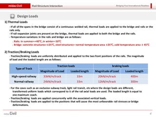
![Bridging Your Innovations to Realitiesmidas Civil
2
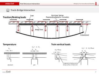
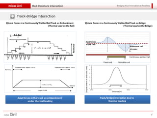
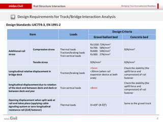
Rail Structure Interaction
Overview
1) Definition of Continuous Welded Rail (CWR)
Rails are continuously welded and thus, the length of one rail is longer than 200m.
ex > standard length rail (L=25m), longer rail (L=25~200m)
2) Necessity of Continuous Welded Rail
Time[ms]
Dynamicamplification
Q
Q
6
5
4
3
2
1
0
16 18 20 221412108642
Wheel/rail impact forces
Wheel impact
forces occur
- The reduced impact force in the rails increases the life span of the rails and improves the ride quality.
- The decreasing noise and vibration by the reduced impact force is less impeding the ambient environment.
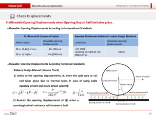
3) Check Points for Continuous Welded Rail
- When temperature rises: track deformation
(buckling of rail)
- When temperature drops: fracture failure](https://image.slidesharecdn.com/railbridgeandcompositegirderbridgeanalysis-130506001939-phpapp02/85/Rail-bridge-and-composite-girder-bridge-analysis-2-320.jpg)


1) The document discusses continuous welded rail (CWR) structures and the interaction between railway tracks and bridges. CWR reduces impact forces in the rails, increasing lifespan and improving ride quality. 2) Key considerations for CWR include buckling from high temperatures and fracture from low temperatures. Track-bridge interaction is also analyzed under various loads like temperature, traction, braking, and train forces. 3) Design requirements specify allowable stresses and displacements. Models are created to analyze stress and displacement considering load combinations through computational methods like finite element analysis.


![Project_midas[1].pptx](https://cdn.slidesharecdn.com/ss_thumbnails/projectmidas1-230612033725-710bb305-thumbnail.jpg?width=640&height=640&fit=bounds)


