Download to read offline
![International Research Journal of Engineering and Technology (IRJET) e-ISSN: 2395-0056
Volume: 05 Issue: 12 | Dec 2018 www.irjet.net p-ISSN: 2395-0072
© 2018, IRJET | Impact Factor value: 7.211 | ISO 9001:2008 Certified Journal | Page 419
F) Ratio(D/E) = 10.27/6.79 = 1.53,
Hence outer wheel rotates 1.53 times faster than inner
wheel.
Reduction between spider gears and side gears
= 1.53
= 1.8 (considering available modules.)
2.2 Material Selection for Gears
Table-1: Material Selection Chart
Material
Properties
20MnCr5
Steel
EN 8 Steel EN19 Steel
Tensile
yield
Strength
(Mpa)
750 433 470
Tensile
ultimate
Strength
(Mpa)
1000 650 745
Density
(kg/m3) 7850 7800 7800
Hence considering more tensile strength and more ultimate
strength with optimum material cost, 20MnCr5 steel was
finalized as gear material.
2.3 Gear Teeth Calculations
Fig-3: Bevel gear terminology
Assuming,
Pitch circle diameter of gear (Dg) = 72mm
No. of teeth on gear (Zg) = 18,
Pitch circle diameter of pinion (Dp) = 40mm
No. of teeth on pinion (Zp) = 10
Reduction = 1.8, Module = 4mm,
Addendum (ha)= 4mm, dedendum (hf)= 5mm (According
to stub involute profile)
According to design data book,
Material used = 20MnCr5,
Syt = 750Mpa
Sut = 1000Mpa.
Case hardness = 42HRc (Material to be case hardened for
pinion only.)
Pitch cone angles are,
γp = tan-1 (zp/zg)ASD
γp = tan-1 (10/18)
=29.05°
γg =60.95°
Beam strength (σb) = sut/3
=1000/3
(σb) =333.33N/mm^2
Virtual number of teeth on pinion (Z`p)
= Zp/cos (γp)
=10/cos(29.05)
Z`p = 11.439
Similarly,
Virtual number of teeth on gear (Z`g) = 37.069
The pinion is designed considering bending,
Dp = m*Zp
= 4*10
Dp = 40mm
Similarly,
Dg = 72mm
Pitch cone distance (Ao) =√(dp/2)^2+(dg/2)^2
=√40/2)^+(72/2)^
Ao = 41.182mm
Lewis form factor (Y`p) = 0.55-(2.64/z`)
= 0.55-(2.64/11.439)
∴ (z` is 20 for stub involute profile)
Y`p = 0.3192
Beam strength (Fb) = σb *b*m*Y`p[1-(b/Ao)]
=333.33*13.727*4Z*0.3192[1-(13.727/41.182)]
Fb=3894.768N
Ratio factor (Q`) = 2*Z`g/ (Z`p+Z`g)
= 2*37.069/ (11.439+37.069)
Q`= 1.5283
Load stress factor (K) = 0.16[BHN/100]^2
= 0.16[400/100]^2
K = 2.56N/mm^2
Wear strength (Fw)= 0.75*dp*b*Q*K/[cos(γp)]
=0.75*40*13.727*1.5283*2.56/0.8742
Fw=1843.047N
As,Fb>Fw; Gear pair is designed for pitting.
V= *dp*np/(60*1000)
=π*40*1080/(60*1000)
V=2.2619m/s
Tangential force (Ft) = P/V
= 12000/2.2619
Ft = 5305.165N
Velocity factor(Kv) = 6/(6+V)
= 6/(6+2.2619)
Kv = 0.72622
Effective load (Feff) = Ka*Km*Ft/Kv
= 1.25*1*5305.165/0.72622
Feff = 9131.40N
Hence, to avoid pitting failure we consider factor of safety of
1.75](https://image.slidesharecdn.com/irjet-v5i1280-181229053311/75/IRJET-Design-and-Development-of-Open-Differential-for-Transmission-System-of-Quad-Bike-2-2048.jpg)
![International Research Journal of Engineering and Technology (IRJET) e-ISSN: 2395-0056
Volume: 05 Issue: 12 | Dec 2018 www.irjet.net p-ISSN: 2395-0072
© 2018, IRJET | Impact Factor value: 7.211 | ISO 9001:2008 Certified Journal | Page 420
Fw = Nf * Feff
= 1.75*9131.40
Fw = 15979.958N
Mean radius of bevel pinion (rmp)
=(dp/2)-[b*sin(γp)/2]
= (40/2)-[13.727*sin(29.05)/2]
rmp = 16.6672 mm
Similarly,
Mean radius of bevel gear (rmg)=29.99mm
According to IS grade 6, pitch error is given by the equation,
e = 8.0+0.63[m+0.25*√rm]
For pinion, ep =8.0+0.63[m+0.25*√rmp]
=8.0+0.63[4+0.25*√2*16.6672
ep = 11.429 m
Similarly,
For gear,eg =11.739µm
Pitch error on meshing teeth © = ep + eg
=11.426+11.72
e=23.168*10^-3mm
Ftmax = Ka*Km*Ft
= 1.25*1.* 5305.165
Ftmax = 6631.456N
For steel pinion and steel gear deformation factor is given
by,
C = 11000*e
= 11000*30*10^-3
C = 330N/mm
By using Buckingham’s equation, dynamic loading is given
by,
Fd = 21*V*(bC+Ftmax)/[21V+√bc+Ftmax]
=21*2.2619*(13.727*330+6631.456)/[21*2.2619+ 13.727*
330+6631.456]
Fd = 3461.79N
Feff = Ka*Km*Ft+Fd
= 1.25*1*5305.165+3247.176N
Feff = 10093.25N
Nf = Fw/Feff
=23997.64/12392.13
Nf= 1.583
Hence, design is safe
2.4 Bearing Calculations
Inner Bearings :
Fig-4: Free body diagram of differential
Forces on gear:-
Ft =p/v
=12*10^3/2.26
Ft =5305.16N
Radial forces on gear:-
Frp = Ft*tan (ϕ)*cos(γp)
=5305.16*tan(20)*cos(29.05)
Frp =1688N
Frg=Ft*tan(ϕ )cos(γg)
=5305.16*tan(20*cos(60.95)
Frg=937.602N
Axial forces on gear:-
Fag=Ftm*tan(ϕ)*sin(γp)
=5305.16*tan(20)*sin(29.05)
Fap=937.602N
Fag=Ftm*tan(ϕ)*sin(γp)
=5305.16*tan(20)*sin(60.95)
Fag=1688N
=5305.16*2.26
Resultant load on bearing:
Fig -5: Vertical loading diagram
Moment about A:
(Rbv*80)+(957.602*20)+(20*40)-(957.602*60)=0
Rbv = 468.801N
Similarly moment about B gives;
Rav = -448.801N
Fig -6: Horizontal loading diagram
Moment about B:
(Rah*80)+(5305.16*60)-(1688*36)-
(5305.16*20)+(1688*36)=0
Rah = -2652.58N
Rah = 103.782652.58N
Resultant load on bearing:
Ra= 2690.279 N
Rb=2693.68 KN
Lh10=12000
n = 600](https://image.slidesharecdn.com/irjet-v5i1280-181229053311/75/IRJET-Design-and-Development-of-Open-Differential-for-Transmission-System-of-Quad-Bike-3-2048.jpg)
![International Research Journal of Engineering and Technology (IRJET) e-ISSN: 2395-0056
Volume: 05 Issue: 12 | Dec 2018 www.irjet.net p-ISSN: 2395-0072
© 2018, IRJET | Impact Factor value: 7.211 | ISO 9001:2008 Certified Journal | Page 425
6. CONCLUSION
The differential assembly, after implementation in quad
vehicle, satisfies the design requirements. It proves to be
durable on rough terrain and critical operating conditions.
No traction difference problem was observed and vehicle
could maneuver sharp turns without losing traction. Thus,
we can conclude that initial objective of differential for
transmission system of quad vehicle is satisfied and serves
as ground for further research on said system.
7. REFERENCES
[1] Milliken and Milliken, Race Car Vehicle Dynamics.
[2] C. Smith, “Tune to Win”, AERO publishers Inc.
[3] V.D. Kodgire, ‘Material Science and Metallurgy’
[4] V.B. Bhandari, ‘Design of Machine Elements’](https://image.slidesharecdn.com/irjet-v5i1280-181229053311/75/IRJET-Design-and-Development-of-Open-Differential-for-Transmission-System-of-Quad-Bike-8-2048.jpg)

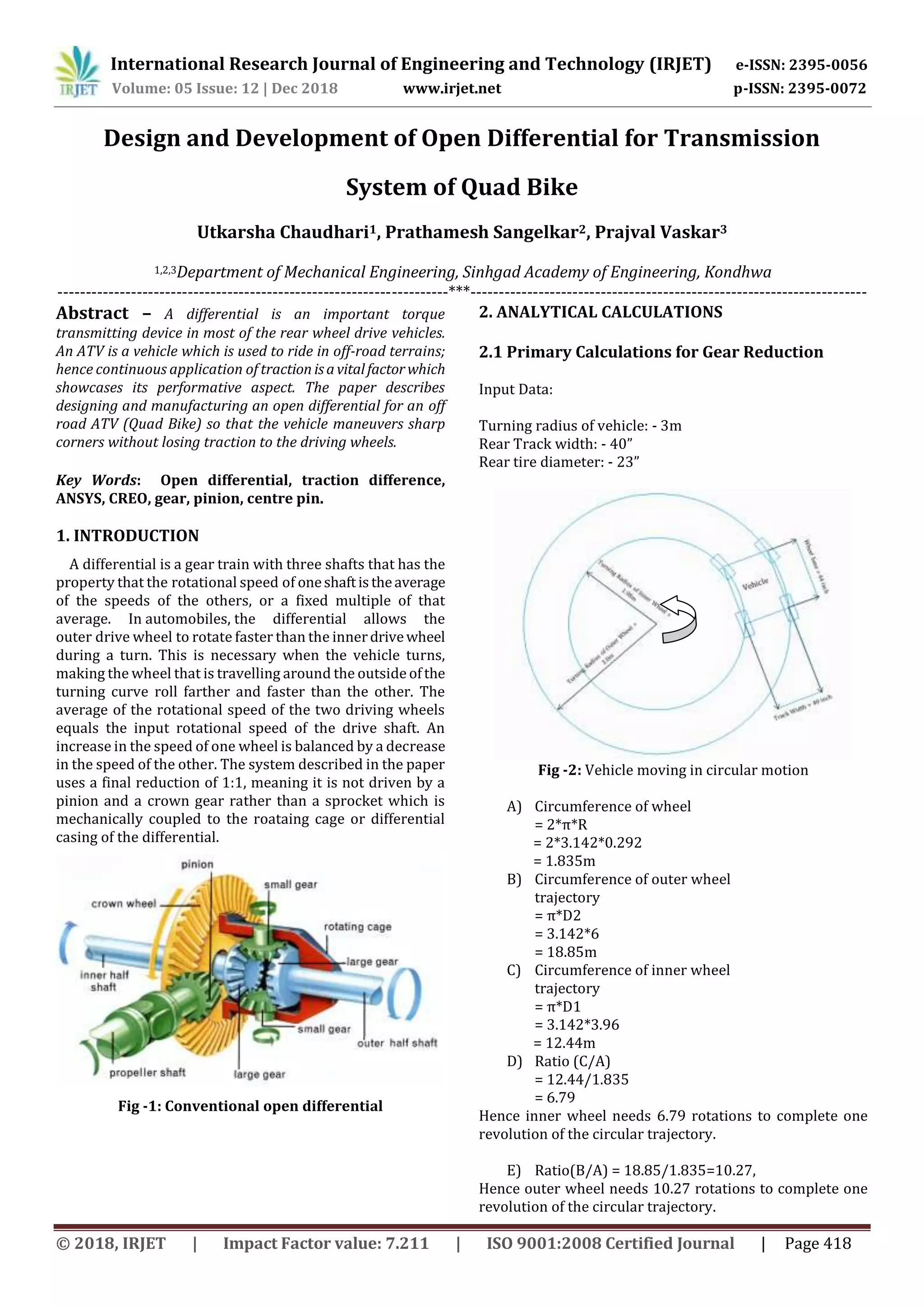
This document describes the design and development of an open differential for an all-terrain vehicle (ATV). The authors first perform analytical calculations to determine the required gear ratios and sizes based on the vehicle's dimensions and performance requirements. They select materials and design the gears to withstand bending and contact stresses. Bearings are sized to support the radial and axial loads from the gears. The differential components, including gears, pinion, and center pin, are then modeled in CAD software. In summary, the authors designed and analyzed an open differential through calculations and CAD modeling to transmit torque from the transmission to the wheels of an ATV.


![Assignment [4] machining with solutions](https://cdn.slidesharecdn.com/ss_thumbnails/assignment4machining-withsolutions-121213110841-phpapp02-thumbnail.jpg?width=640&height=640&fit=bounds)


