Download to read offline
![International Research Journal of Engineering and Technology (IRJET) e-ISSN: 2395-0056
Volume: 05 Issue: 04 | Apr-2018 www.irjet.net p-ISSN: 2395-0072
© 2018, IRJET | Impact Factor value: 6.171 | ISO 9001:2008 Certified Journal | Page 717
Regenerative Suspension System
Prof.P.B.Magade1, Manoj Narute2, Suraj Kinhale3, Mahesh Kutwal4, Yogesh Marakad5
1,2,3,4,5 Dept. of Mechanical Engineering, Zeal College of Engineering and Research
Narhe, Pune, Maharashtra, India
-----------------------------------------------------------------------------***----------------------------------------------------------------------------
Abstract: In India capacity of power consumption is
increased because industrialization and standard of human
life is incrcreased. Now a days vehicle became a basic need
of human hence the production of vehicles as well as
demand of vehicles are increasing. Hence number of vehicles
on road are increased. Therefore accidents are increasing.
One of the best way to minimize the accidents is to install
the speed breakers in front of school, hospital, temple,
railway crossing etc. Due to speed breaker rider maintain
minimum speed and chances of accidents are reduced. Speed
breaker oppose the vehicle and impact force is created in
suspension system. By using impact force power is
generated with the help of dynamo and alternator. The
generated power is used to charge the battery. About 100-
400 watts power is generated with the help of middle size
vehicles like car, taxies etc.
Key words: Speed breakers, Impact Energy ,
Regenerative suspension system, Alternator, Dynamo
and Battery
1. INTRODUCTION
The number of vehicles are travelled on a road. The road
may be rough or smooth. On rough road more vibrations
are created as compare to smooth road. These vibrations
are not used for any purpose and vibrations are wasted.
Vibrations are commonly wasted in forms of thermal
energy.. By using regenerative suspension system 100-400
watts average power is generated with the help of middle
size vehicles. Middle-size passenger vehicle needs 180 to
200 watts power for various processes like fuel ignition
and injection processes. Also the middle size vehicles
requires 250 to 260 watts power for lighting system like
head light, front light, main lamp etc.
The total need of power of middle size vehicles for various
requirement is about 180 to 400 watts. By using
regenerative suspension system it is possible that to
charge the battery of vehicle. Therefore load on the vehicle
engine is reduced and the requirement of fuel is reduced
at certain level. Thus by using regenerative suspension
system charging of battery as well as fuel consumption is
reduced.[5]
2. LITERATURE SURVEY
Larry Weng ,Geoff Walker et.al[1] have researched on
energy storage system for regenerative dynamometers. In
this paper, various types of dynamometers have been
researched. One of those is regenerative dynamometer. In
this mechanical energy is converted into electrical energy
for charging the battery.
Zhang Jin-qiu, PengZhi-zhao et.al[2] studied on energy
conversion system in suspension system. The regenerative
suspension systems have attracted much attention in
recent years for the improvement of vibrating attenuating
performance and reduction of energy dissipation.
Jun Yin ,Xinbo Chen et.al[3] have researched on how to
design and analyze regenerative suspension system. From
this paper we come to know that how to design the
kinematics of this system. To achieve better suspension
performance. The regenerative suspension system should
be controlled in consider of the kinematics and dynamics
of the system. The advantage of regenerative suspension
system is demonstrated by comparison with suspension
performance of passive suspension system. MohdAzman
Abdullah , JazliFirdausJamil et.al[4] have studied and
developed a device to harvest vibrational energy . Based
on the frequency and amplitude of potential vibrations a
device is designed and developed. This device is further
assembled in a passenger vehicle.[4]
3. OBJECTIVES
1. To generate the reciprocating motion as a prime
input.
2. To convert reciprocating motion into rotary motion
by rack and pinion.
3. To magnify the rotary motion using chain drive.
4. To store the kinetic energy using flywheel.
5. To transfer the energy to dynamo and to generate
electricity.
6. To light up the indicator lamps attached to system as
final output.
7. To conserve the vibrational energy which is being
dissipated as heat.
4. DESIGN CALCULATION
The various steps for designing are as follows:
4.1.Nomenclature:
m = Mass of the flywheel k = Radius of gyration](https://image.slidesharecdn.com/irjet-v5i4158-190220063041/85/IRJET-Regenerative-Suspension-System-1-320.jpg)
![International Research Journal of Engineering and Technology (IRJET) e-ISSN: 2395-0056
Volume: 05 Issue: 04 | Apr-2018 www.irjet.net p-ISSN: 2395-0072
© 2018, IRJET | Impact Factor value: 6.171 | ISO 9001:2008 Certified Journal | Page 718
I = Mass moment of inertia Pd=Diameter pitch m=Module
A = Addendum
B = Deddendum
Pc = Circular Pitch
ρ = Density of concrete
K1= Load factor
K2= Factor for distance regulation
K3=Factor for center distance of sprocket
K4=Factor for position of sprocket
K5=Lubrication factor
K6=Rating factor
T1 = Tension in tight side
T2 = Tension in slack side
Dact =Actual diameter of shaft Tmax= Maximum torque on
shaft
4.2.Calculation:
Let the force put by human hand on rack = 30 kg.[9]
30x10 =300 N
In one minute rack will go up & down 30 times . Now
pinion has 24 number of teeth so in 1 minute pinion Rpm
will be 15 because only 12 teeth will come in contact at a
time only with rack.
Now,
Gear-1, teeth = 44 and Rpm = 15
Gear-2, teeth = 18
Gear teeth ratio = 18:44
=1:2.4
Speed of gear-2 = 2.4x15
= 36 Rpm
Rpm of flywheel is 85 Rpm.
Diameter of flywheel = 350mm = 0.350 m
Width of flywheel = 80mm =0.080 m
.‘. Volume of flywheel = π x r2 x b
= 0.007696 m3.
Flywheel is filled with concrete inside.
ρ = 2400 kg/m3.
.’. Mass of flywheel = 0.007696 x 2400 = 18.47 kg
The mean kinetic energy of the flywheel, E =1/2 .I .ω2
=1/2m.k2.ω2
= 0.6293 N-mm
Velocity ratio = 50 : 350
= 1 : 7
Speed of dynamo pulley = 85 x 7 = 595 Rpm. Purchase 500
Rpm standard dynamo from the market, which produce 10
watts power at full speed.
Torque transmitted by shaft,
T = π/16 x τ x d3
Select permissible shear stress (τ) from design data book (
V.B. Bhandari)
τ = 70 N/mm2
Thus, 9750 = π /16 x d3 x 70 d=8.91mm
Taking factor of safety = 1.8
Dact = 8.9 x 1.8 = 16 mm
Select diameter of shaft = 20 mm.
For 20mm shaft diameter take standard bearing. Spherical
ball or deep groove ball bearing
= 20mm
Spur gear terminology,
Take the gear of teeth, T = 24 D = 65mm b= 25mm.
Calculate spur gear terminology and check whether it can
bear load.
Pd = T/D = 24/65 = 0.37 mm. m = D/T = 65/24 = 2.70mm.
Pc = πD/T = π x 65/24 = 8.50 mm.
A = 1/Pd= 1/0.37 = 2.70mm.
B = 1.157/Pd = 1.157/0.37 = 3.13 mm.
Root diameter = T-2/Pd = 22/0.37 = 59.45 mm.
Base circle = D x Cos(Pd x A) = 65 x cos(0.37x2.70) =
64.99mm.](https://image.slidesharecdn.com/irjet-v5i4158-190220063041/85/IRJET-Regenerative-Suspension-System-2-320.jpg)
![International Research Journal of Engineering and Technology (IRJET) e-ISSN: 2395-0056
Volume: 05 Issue: 04 | Apr-2018 www.irjet.net p-ISSN: 2395-0072
© 2018, IRJET | Impact Factor value: 6.171 | ISO 9001:2008 Certified Journal | Page 721
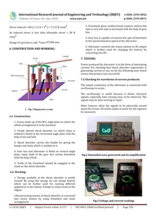
7.2.Testing for power generated:
Voltage and current is measured by using multi meter and
power is calculated as follows;
V = 29.06V, I= 1.244 A;
Power = V× I
Power = 36.15VA =36.15 Watt
Fig.4 Testing Setup
8. CONCLUSION
The vibration energy of vehicle suspension system is
wasted in the form of heat energy. By using regenerative
system the wasted energy is converted into the useful
energy like electrical energy and some amount fuel
consumption is reduced. All types regenerative suspension
are commonly electromagnetic suspension. From the
appearance of full performance including oscillation guide
capacity, regenerative efficiency and application
reliability. By using advanced technology regenerative
system can became important in vehicle manufacturing
industry.
By using regenerative system electrical energy is
produced. When vehicle come through a rough road that
time more energy is created as compare to smooth road
through alternator. Battery is connected to alternator and
charges the battery.
9. REFERENCES
[1] “Selection of Energy Storage System for a
Regenerative Dynamic Dynamometer .’’ Larry Weng
Geoff Walker Zhao Yang Dong Andrew Simpson David
Finn.
[2] “Review on Energy-Regenerative Suspension
Systems for Vehicles” Zhang Jin-qiu, PengZhi- zhao,
Zhang Lei, Zhang Yu.
[3] “Design and Analysis of an Active and Energy
Regenerative Suspension” Jun Yin , Xinbo Chen Jianqin
Li .
[4] “Harvesting Energy from the Vibration of
Suspension of a Passenger Vehicle” MohdAzman
Abdullah , JazliFirdausJamil.
[5] “Design, Fabrication and Testing of Regenerative
Shock Absorber” Dr. S Gopalakann 275634481
www.researchgate.net
[6] “Design of electromagnet ic shock absorbers”
Gupta A, Jendrzejczyk J A, Mulcahy T M and Hull J R
International Journal of Mechanics &Material Design,
Volume 3, Number 3.
[7]“Design and characterization of Electromagnetic
Energy harvester for vehicle suspensions” Lei Zuo,
Brian Scully, JurgenShestani and Yu Zhou Journal of
Smart Materials and Structures Volume 19, Number 4.
[8] “Energy harvesting, ride comfort, and road
handling of regenerative vehicle suspensions” Pei-
Sheng Zhang and Lei Zuo, ASME Journal of Vibration
and Acoustics, 2012.
[9]”Mechanics magazine and journal of the mechanics
institute’’,volume2](https://image.slidesharecdn.com/irjet-v5i4158-190220063041/85/IRJET-Regenerative-Suspension-System-5-320.jpg)

This document discusses a regenerative suspension system that generates electricity from the impact forces created when a vehicle passes over a speed bump. The system uses the impact force to drive a dynamo and alternator, which charges the vehicle's battery and reduces the load on the engine. It estimates that such a system could generate 100-400 watts of power from a mid-sized vehicle. It then provides details on the design calculations for components like the flywheel, gear ratios, sprockets, and testing of the generated power. The conclusion states that vibration energy from the vehicle suspension is normally wasted as heat, but this system converts it to useful electrical energy and can slightly reduce fuel consumption.


![[IJET-V2I3P23] Authors: Dhanashree N Chaudhari, Pundlik N Patil](https://cdn.slidesharecdn.com/ss_thumbnails/ijet-v2i3p23-160711112928-thumbnail.jpg?width=640&height=640&fit=bounds)


