Downloaded 46 times

![SECTION 12 – HELICAL GEARS
Page 9 of 14
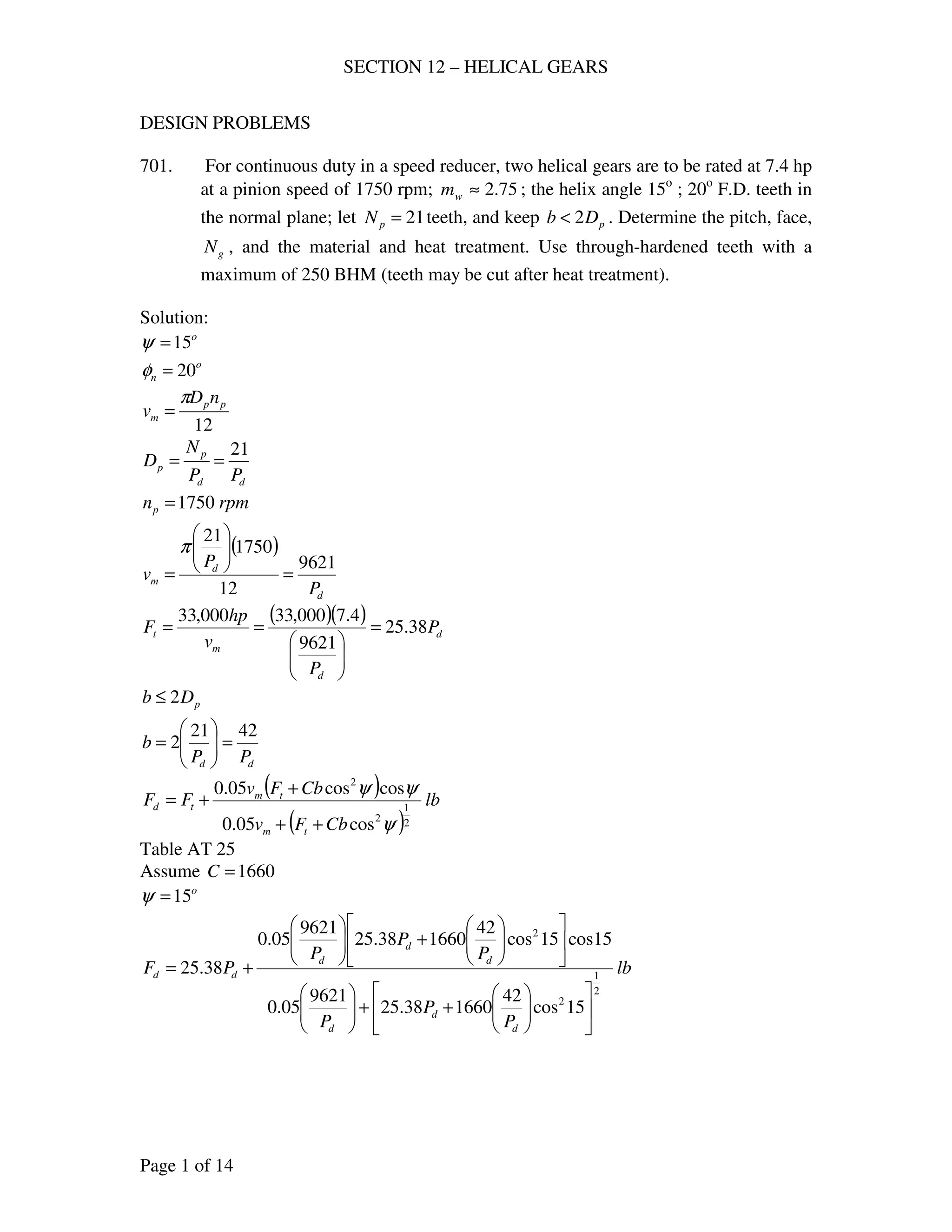
Table AT 24, Load near middle, o
20=nφ
763.0=Y
( )( ) 6.57763.05.75 ==Ysn
For pinion: SAE 4150, OQT to BHN = 350
( ) ksiBHNsu 1753505.05.0 ===
( ) ksiss un 5.871755.05.0 ===
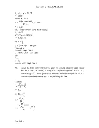
19
12cos
18
cos 33
===
ψ
p
ep
N
N
Table AT 24, Load near middle, o
20=nφ
534.0=Y
( )( ) 7.46534.05.87 ==Ysn
Therefore use pinion as weak
Assume 7.1=fK
( )( )( )
( )( )
lbFs 240,19
57.1
534.05.3500,87
==
For moderate shock, 8 to 10 hr./day
Use 5.1=sfN
dsfs FNF ≥
dF5.1240,19 =
lbFd 827,12≤
Therefore use lbFF wd 5379==
( )
( )
lb
CbFv
CbFv
FF
tm
tm
td
2
1
2
2
cos05.0
coscos05.0
ψ
ψψ
++
+
+=
Fig. AF 20, carefully cut gears, 5=dnP , ine 001.0=
Table AT 25, steel and steel, 20o
FD
1660=C
( )( ) fpm
nD
v pp
m 1686
12
1750681.3
12
===
ππ
( ) ( )[ ]
( ) ( )[ ]
lb
F
F
FF
t
t
td
2
1
2
2
12cos5.31660168605.0
12cos12cos5.31660168605.0
++
+
+=
[ ]
[ ]
lb
F
F
FF
t
t
td 5379
55593.84
555946.82
2
1
=
++
+
+=
Trial and error
lbFt 1800=
( )( ) hp
vF
hp mt
92
000,33
16861800
000,33
===](https://image.slidesharecdn.com/helicalgears-170427092131/85/Design-of-machine-elements-Helical-gears-9-320.jpg)
![SECTION 12 – HELICAL GEARS
Page 10 of 14
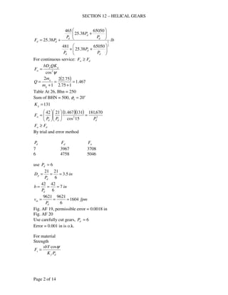
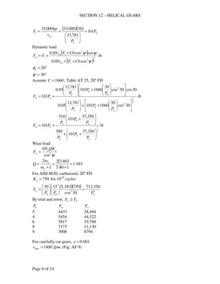
708. Two helical gears are used in a single reduction speed reducer rated at 27.4 hp at
a motor speed of 1750 rpm; continuous duty. The rating allows an occasional 100
% momentary overload. The pinion has 33 teeth. 10=dnP , .2 inb = , o
20=nφ ,
o
20=ψ , 82.2=wm . For both gears, the teeth are carefully cut from SAE 1045
with BHN = 180. Compute (a) the dynamic load, (b) the endurance strength;
estimate 7.1=fK . Also decide whether or not the 100 % overload is damaging.
(c) Are these teeth suitable for continuous service? If they are not suitable
suggest a cure. (The gears are already cut.)
Solution:
d
p
p
P
N
D =
( ) 66.915cos10cos === ψdnd PP
inDp 42.3
66.9
33
==
( )( ) fpm
nD
v pp
m 1567
12
175042.3
12
===
ππ
( ) lb
v
hp
F
m
t 577
1567
4.27000,33000,33
===
(a) Dynamic load
( )
( )
lb
CbFv
CbFv
FF
tm
tm
td
2
1
2
2
cos05.0
coscos05.0
ψ
ψψ
++
+
+=
Fig. AF 20, carefully cut gears, 10=dnP , ine 001.0=
Table AT 25, steel and steel, 20o
FD
1660=C
inb 2=
( ) ( )[ ]
( ) ( )[ ]
lbFd 2578
15cos21660577156705.0
15cos15cos21660577156705.0
577
2
1
2
2
=
++
+
+=
(b) Endurance strength
lb
PK
sbY
F
dnf
s =
For SAE 1045, BHN = 180
( ) ksiBHNsu 901805.05.0 ===
( ) ksiss un 45905.05.0 ===
37
15cos
33
cos 33
===
ψ
p
ep
N
N
Table AT 24, Load near middle, o
20=nφ](https://image.slidesharecdn.com/helicalgears-170427092131/85/Design-of-machine-elements-Helical-gears-10-320.jpg)
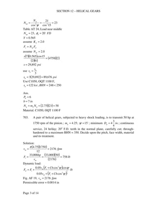
![SECTION 12 – HELICAL GEARS
Page 11 of 14
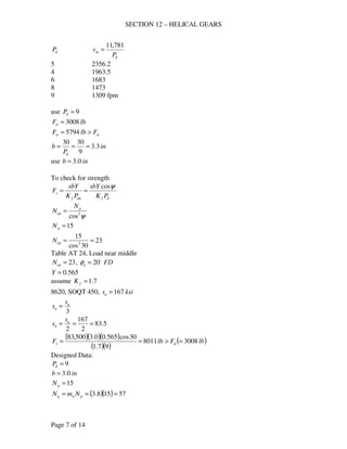
645.0=Y
7.1=fK
( )( )( )
( )( )
lb
PK
sbY
F
dnf
s 3415
107.1
645.02000,45
===
For 100 % overload
( ) lbFt 11545772 ==
( )
( )
lb
CbFv
CbFv
FF
tm
tm
td
2
1
2
2
cos05.0
coscos05.0
ψ
ψψ
++
+
+=
( ) ( )[ ]
( ) ( )[ ]
lbFd 3475
15cos216601154156705.0
15cos15cos216601154156705.0
1154
2
1
2
2
=
++
+
+=
Since ds FF ≈ , 100 % overload is not damaging
(c)
ψ2
cos
gp
w
QKbD
F =
.2 inb =
( ) 476.1
182.2
82.22
1
2
=
+
=
+
=
w
w
m
m
Q
Table AT 26, o
20=nφ
Sum of BHN = 2(180) = 360
5.62=gK
( )( )( )( ) ( )lbFlbF dw 2578676
15cos
5.62476.142.32
2
=<==
Therefore not suitable for continuous service.
Cure: Through hardened teeth
For Bhn
( ) 2385.62
676
2578
==gK
min Bhn = 0.5(650) = 325
709. Two helical gears are used in a speed reducer whose input is 100 hp at 1200 rpm,
from an internal combustion engine. Both gears are made of SAE 4140, with the
pinion heat treated to a BHN 363 – 415, and the gear to 321 – 363; let the teeth
be F.D.; 20o
pressure angle in the normal plane; carefully cut; helix angle
o
15=ψ ; 22=pN , 68=gN teeth; 5=dP , inb 4= . Calculate the dynamic load,
the endurance strength load, and the limiting wear load for the teeth. Should these
gears have long life if they operate continuously? (Data courtesy of the Twin
Disc Clutch Co.)
Solution:](https://image.slidesharecdn.com/helicalgears-170427092131/85/Design-of-machine-elements-Helical-gears-11-320.jpg)
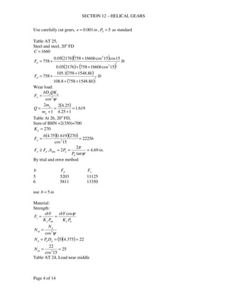
![SECTION 12 – HELICAL GEARS
Page 12 of 14
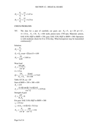
in
P
N
D
d
p
p 4.4
5
22
===
( )( ) fpm
nD
v pp
m 1382
12
12004.4
12
===
ππ
( ) lb
v
hp
F
m
t 2388
1382
100000,33000,33
===
Dynamic load
( )
( )
lb
CbFv
CbFv
FF
tm
tm
td
2
1
2
2
cos05.0
coscos05.0
ψ
ψψ
++
+
+=
Fig. AF 20, carefully cut gears, 5=dnP , ine 001.0=
Table AT 25, steel and steel, 20o
FD
1660=C
inb 4=
( ) ( )[ ]
( ) ( )[ ]
lbFd 5930
15cos416602388138205.0
15cos15cos416602388138205.0
2388
2
1
2
2
=
++
+
+=
Endurance strength load
lb
PK
sbY
F
df
s
ψcos
=
Assume 7.1=fK
Pinion
( ) ksiBHNsn 75.9036325.025.0 ===
25
15cos
22
cos 33
===
ψ
p
ep
N
N
Table AT 24, Load near middle, o
20=nφ
580.0=Y
( )( )( )
( )( )
lb
PK
sbY
F
df
s 925,23
57.1
15cos580.04750,90cos
===
ψ
Gear
( ) ksiBHNsn 25.8032125.025.0 ===
75
15cos
68
cos 33
===
ψ
p
ep
N
N
Table AT 24, Load near middle, o
20=nφ
735.0=Y
( )( )( )
( )( )
lb
PK
sbY
F
df
s 811,26
57.1
15cos735.04250,80cos
===
ψ
use lbFs 925,23=](https://image.slidesharecdn.com/helicalgears-170427092131/85/Design-of-machine-elements-Helical-gears-12-320.jpg)

This document provides information on designing helical gears, including formulas and example problems and solutions. It discusses topics such as determining pitch, face width, material selection, heat treatments, transmission capacity calculations, and checking designs for strength. An example problem is provided to determine the pitch, face, number of teeth, material, and heat treatment for two helical gears rated to transmit 7.4 hp at 1750 rpm.


