The document outlines the design calculations for a 315kVA distribution transformer. It includes chapters on introduction, implementation program, design calculation, and conclusion. The design calculation chapter calculates the failure analysis, vibration mode, and dynamic force analysis of the transformer. It determines stresses, equivalent moments, shear stress on components, reactions at bearings from forces, and total torque on the crankshaft. The conclusion states that stresses, forces and torques were calculated to analyze failure points and ensure the transformer meets technical requirements.
Để xem full tài liệu Xin vui long liên hệ page để được hỗ trợ
: https://www.facebook.com/thuvienluanvan01
HOẶC
https://www.facebook.com/garmentspace/
https://www.facebook.com/thuvienluanvan01
https://www.facebook.com/thuvienluanvan01
tai lieu tong hop, thu vien luan van, luan van tong hop, do an chuyen nganh
Diseno en ingenieria mecanica de Shigley - 8th ---HDes
descarga el contenido completo de aqui http://paralafakyoumecanismos.blogspot.com.ar/2014/08/libro-para-mecanismos-y-elementos-de.html
Design of an automotive differential with reduction ratio greater than 6eSAT Publishing House
IJRET : International Journal of Research in Engineering and Technology is an international peer reviewed, online journal published by eSAT Publishing House for the enhancement of research in various disciplines of Engineering and Technology. The aim and scope of the journal is to provide an academic medium and an important reference for the advancement and dissemination of research results that support high-level learning, teaching and research in the fields of Engineering and Technology. We bring together Scientists, Academician, Field Engineers, Scholars and Students of related fields of Engineering and Technology
Watch Video of this presentation on Link: https://youtu.be/bHKaPBgDk6g
For notes/articles, Visit my blog (link is given below).
For Video, Visit our YouTube Channel (link is given below).
Any Suggestions/doubts/reactions, please leave in the comment box.
Follow Us on
YouTube: https://www.youtube.com/channel/UCVPftVoKZoIxVH_gh09bMkw/
Blog: https://e-gyaankosh.blogspot.com/
Facebook: https://www.facebook.com/egyaankosh/
Để xem full tài liệu Xin vui long liên hệ page để được hỗ trợ
: https://www.facebook.com/thuvienluanvan01
HOẶC
https://www.facebook.com/garmentspace/
https://www.facebook.com/thuvienluanvan01
https://www.facebook.com/thuvienluanvan01
tai lieu tong hop, thu vien luan van, luan van tong hop, do an chuyen nganh
COMPARATIVE ANALYSIS OF CRANKSHAFT IN SINGLE CYLINDER PETROL ENGINE CRANKSHAF...ijiert bestjournal
The crankshaft is also referred as crank. It is responsible for conversion between reciprocating
motion and rotational motion. In a reciprocating engine, it translates reciprocating linear piston
motion into rotational motion. In a reciprocating compressor, it converts the rotational motion
into reciprocating motion. Here the failure of crankshafts for two wheelers mostly occurs in the
crankpin. Thus the crankpin is an important component that mostly decides the life of the
crankshaft. The crankshaft considered here is of Pulsar 180 DTSi. It is a petrol engine crankshaft
made from Alloy steel 41Cr4.Abnormal sound was heard in crankshaft while it is in operation. It
was identified as failure of crankshaft. Severe wear has been observed at crankpin bearing
location where the oil hole is provided. Here the analysis of the two wheeler crankshaft is done.
Its results are then compared and verified numerically, then by the use of ANSYS software. The
results compared here are Von Mises Stresses and the strain occurring on the crankshaft.
Để xem full tài liệu Xin vui long liên hệ page để được hỗ trợ
: https://www.facebook.com/thuvienluanvan01
HOẶC
https://www.facebook.com/garmentspace/
https://www.facebook.com/thuvienluanvan01
https://www.facebook.com/thuvienluanvan01
tai lieu tong hop, thu vien luan van, luan van tong hop, do an chuyen nganh
Diseno en ingenieria mecanica de Shigley - 8th ---HDes
descarga el contenido completo de aqui http://paralafakyoumecanismos.blogspot.com.ar/2014/08/libro-para-mecanismos-y-elementos-de.html
Design of an automotive differential with reduction ratio greater than 6eSAT Publishing House
IJRET : International Journal of Research in Engineering and Technology is an international peer reviewed, online journal published by eSAT Publishing House for the enhancement of research in various disciplines of Engineering and Technology. The aim and scope of the journal is to provide an academic medium and an important reference for the advancement and dissemination of research results that support high-level learning, teaching and research in the fields of Engineering and Technology. We bring together Scientists, Academician, Field Engineers, Scholars and Students of related fields of Engineering and Technology
Watch Video of this presentation on Link: https://youtu.be/bHKaPBgDk6g
For notes/articles, Visit my blog (link is given below).
For Video, Visit our YouTube Channel (link is given below).
Any Suggestions/doubts/reactions, please leave in the comment box.
Follow Us on
YouTube: https://www.youtube.com/channel/UCVPftVoKZoIxVH_gh09bMkw/
Blog: https://e-gyaankosh.blogspot.com/
Facebook: https://www.facebook.com/egyaankosh/
Để xem full tài liệu Xin vui long liên hệ page để được hỗ trợ
: https://www.facebook.com/thuvienluanvan01
HOẶC
https://www.facebook.com/garmentspace/
https://www.facebook.com/thuvienluanvan01
https://www.facebook.com/thuvienluanvan01
tai lieu tong hop, thu vien luan van, luan van tong hop, do an chuyen nganh
COMPARATIVE ANALYSIS OF CRANKSHAFT IN SINGLE CYLINDER PETROL ENGINE CRANKSHAF...ijiert bestjournal
The crankshaft is also referred as crank. It is responsible for conversion between reciprocating
motion and rotational motion. In a reciprocating engine, it translates reciprocating linear piston
motion into rotational motion. In a reciprocating compressor, it converts the rotational motion
into reciprocating motion. Here the failure of crankshafts for two wheelers mostly occurs in the
crankpin. Thus the crankpin is an important component that mostly decides the life of the
crankshaft. The crankshaft considered here is of Pulsar 180 DTSi. It is a petrol engine crankshaft
made from Alloy steel 41Cr4.Abnormal sound was heard in crankshaft while it is in operation. It
was identified as failure of crankshaft. Severe wear has been observed at crankpin bearing
location where the oil hole is provided. Here the analysis of the two wheeler crankshaft is done.
Its results are then compared and verified numerically, then by the use of ANSYS software. The
results compared here are Von Mises Stresses and the strain occurring on the crankshaft.
Water scarcity is the lack of fresh water resources to meet the standard water demand. There are two type of water scarcity. One is physical. The other is economic water scarcity.
Vaccine management system project report documentation..pdfKamal Acharya
The Division of Vaccine and Immunization is facing increasing difficulty monitoring vaccines and other commodities distribution once they have been distributed from the national stores. With the introduction of new vaccines, more challenges have been anticipated with this additions posing serious threat to the already over strained vaccine supply chain system in Kenya.
Forklift Classes Overview by Intella PartsIntella Parts
Discover the different forklift classes and their specific applications. Learn how to choose the right forklift for your needs to ensure safety, efficiency, and compliance in your operations.
For more technical information, visit our website https://intellaparts.com
Saudi Arabia stands as a titan in the global energy landscape, renowned for its abundant oil and gas resources. It's the largest exporter of petroleum and holds some of the world's most significant reserves. Let's delve into the top 10 oil and gas projects shaping Saudi Arabia's energy future in 2024.
Overview of the fundamental roles in Hydropower generation and the components involved in wider Electrical Engineering.
This paper presents the design and construction of hydroelectric dams from the hydrologist’s survey of the valley before construction, all aspects and involved disciplines, fluid dynamics, structural engineering, generation and mains frequency regulation to the very transmission of power through the network in the United Kingdom.
Author: Robbie Edward Sayers
Collaborators and co editors: Charlie Sims and Connor Healey.
(C) 2024 Robbie E. Sayers
About
Indigenized remote control interface card suitable for MAFI system CCR equipment. Compatible for IDM8000 CCR. Backplane mounted serial and TCP/Ethernet communication module for CCR remote access. IDM 8000 CCR remote control on serial and TCP protocol.
• Remote control: Parallel or serial interface.
• Compatible with MAFI CCR system.
• Compatible with IDM8000 CCR.
• Compatible with Backplane mount serial communication.
• Compatible with commercial and Defence aviation CCR system.
• Remote control system for accessing CCR and allied system over serial or TCP.
• Indigenized local Support/presence in India.
• Easy in configuration using DIP switches.
Technical Specifications
Indigenized remote control interface card suitable for MAFI system CCR equipment. Compatible for IDM8000 CCR. Backplane mounted serial and TCP/Ethernet communication module for CCR remote access. IDM 8000 CCR remote control on serial and TCP protocol.
Key Features
Indigenized remote control interface card suitable for MAFI system CCR equipment. Compatible for IDM8000 CCR. Backplane mounted serial and TCP/Ethernet communication module for CCR remote access. IDM 8000 CCR remote control on serial and TCP protocol.
• Remote control: Parallel or serial interface
• Compatible with MAFI CCR system
• Copatiable with IDM8000 CCR
• Compatible with Backplane mount serial communication.
• Compatible with commercial and Defence aviation CCR system.
• Remote control system for accessing CCR and allied system over serial or TCP.
• Indigenized local Support/presence in India.
Application
• Remote control: Parallel or serial interface.
• Compatible with MAFI CCR system.
• Compatible with IDM8000 CCR.
• Compatible with Backplane mount serial communication.
• Compatible with commercial and Defence aviation CCR system.
• Remote control system for accessing CCR and allied system over serial or TCP.
• Indigenized local Support/presence in India.
• Easy in configuration using DIP switches.
NO1 Uk best vashikaran specialist in delhi vashikaran baba near me online vas...Amil Baba Dawood bangali
Contact with Dawood Bhai Just call on +92322-6382012 and we'll help you. We'll solve all your problems within 12 to 24 hours and with 101% guarantee and with astrology systematic. If you want to take any personal or professional advice then also you can call us on +92322-6382012 , ONLINE LOVE PROBLEM & Other all types of Daily Life Problem's.Then CALL or WHATSAPP us on +92322-6382012 and Get all these problems solutions here by Amil Baba DAWOOD BANGALI
#vashikaranspecialist #astrologer #palmistry #amliyaat #taweez #manpasandshadi #horoscope #spiritual #lovelife #lovespell #marriagespell#aamilbabainpakistan #amilbabainkarachi #powerfullblackmagicspell #kalajadumantarspecialist #realamilbaba #AmilbabainPakistan #astrologerincanada #astrologerindubai #lovespellsmaster #kalajaduspecialist #lovespellsthatwork #aamilbabainlahore#blackmagicformarriage #aamilbaba #kalajadu #kalailam #taweez #wazifaexpert #jadumantar #vashikaranspecialist #astrologer #palmistry #amliyaat #taweez #manpasandshadi #horoscope #spiritual #lovelife #lovespell #marriagespell#aamilbabainpakistan #amilbabainkarachi #powerfullblackmagicspell #kalajadumantarspecialist #realamilbaba #AmilbabainPakistan #astrologerincanada #astrologerindubai #lovespellsmaster #kalajaduspecialist #lovespellsthatwork #aamilbabainlahore #blackmagicforlove #blackmagicformarriage #aamilbaba #kalajadu #kalailam #taweez #wazifaexpert #jadumantar #vashikaranspecialist #astrologer #palmistry #amliyaat #taweez #manpasandshadi #horoscope #spiritual #lovelife #lovespell #marriagespell#aamilbabainpakistan #amilbabainkarachi #powerfullblackmagicspell #kalajadumantarspecialist #realamilbaba #AmilbabainPakistan #astrologerincanada #astrologerindubai #lovespellsmaster #kalajaduspecialist #lovespellsthatwork #aamilbabainlahore #Amilbabainuk #amilbabainspain #amilbabaindubai #Amilbabainnorway #amilbabainkrachi #amilbabainlahore #amilbabaingujranwalan #amilbabainislamabad
COLLEGE BUS MANAGEMENT SYSTEM PROJECT REPORT.pdfKamal Acharya
The College Bus Management system is completely developed by Visual Basic .NET Version. The application is connect with most secured database language MS SQL Server. The application is develop by using best combination of front-end and back-end languages. The application is totally design like flat user interface. This flat user interface is more attractive user interface in 2017. The application is gives more important to the system functionality. The application is to manage the student’s details, driver’s details, bus details, bus route details, bus fees details and more. The application has only one unit for admin. The admin can manage the entire application. The admin can login into the application by using username and password of the admin. The application is develop for big and small colleges. It is more user friendly for non-computer person. Even they can easily learn how to manage the application within hours. The application is more secure by the admin. The system will give an effective output for the VB.Net and SQL Server given as input to the system. The compiled java program given as input to the system, after scanning the program will generate different reports. The application generates the report for users. The admin can view and download the report of the data. The application deliver the excel format reports. Because, excel formatted reports is very easy to understand the income and expense of the college bus. This application is mainly develop for windows operating system users. In 2017, 73% of people enterprises are using windows operating system. So the application will easily install for all the windows operating system users. The application-developed size is very low. The application consumes very low space in disk. Therefore, the user can allocate very minimum local disk space for this application.
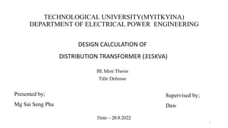
1. TECHNOLOGICAL UNIVERSITY(MYITKYINA)
DEPARTMENT OF ELECTRICAL POWER ENGINEERING
DESIGN CALCULATION OF
DISTRIBUTION TRANSFORMER (315KVA)
BE Mini Thesis
Title Defense
1
Presented by;
Mg Sai Seng Pha
Supervised by;
Daw
Date – 28.8.2022
2. Outlines of Presentation
Introduction
Aim and Objective
Implementation Program
Outlines of thesis
Design Calculation of Distribution Transformer (315V)
Conclusion
Future Plan
2
3. CHAPTER 1
INTRODUCTION
• A crankshaft related to crank is a mechanical part able to perform a
conversion between reciprocating motion and rotational motion.
• In a reciprocating engine, it translates reciprocating motion of the
piston into rotational motion; whereas in a reciprocating compressor,
it converts the rotational motion into reciprocating motion.
• In order to do the conversion between two motions, the crankshaft
has "crank throws" or "crankpins", additional bearing surfaces whose
axis is offset from that of the crank, to which the "big ends" of the
connecting rods from each cylinder attach.
• It is typically connected to a flywheel to reduce the pulsation
characteristic of the four-stroke cycle, and sometimes a torsional or
vibrational damper at the opposite end, to reduce the torsional
vibrations often caused along the length of the crankshaft by the
cylinders farthest from the output end acting on the torsional elasticity
of the metal. 3
4. History of crankshaft
• During the background research, emphasis was given on identifying the morphology of
the crankshaft, the manufacturing techniques that exist now and the thermal treatments in
different stages of the production. The kinematic-kinetic analysis and the balancing
method are also included in the background research.
• Crankshaft is one of the critical components for the effective and precise working of the
internal combustion engine.
• Study is done on the crankshaft and found that there are tremendous stress induced in
crankshaft.
• The Industrial revolution which started in 1760 and finished in 1840 brought into the light
new manufacturing techniques and opened the road for revolutionary inventions, which
are used even today.
• One of the most innovative inventions is the gasoline and diesel engine which made a
huge contribution in the process of the world.
4
5. Project goals
• This project goal is to identify if the crankshaft can be designed in
individual parts in a way that fulfills all the technical requirements.
• Firstly to analyze the single cylinder crankshaft from an engineering
point of view, discussion about single cylinder crankshaft and
secondly, to understand the functionality of the geometry and design
consideration and the third, calculated on single cylinder crankshaft.
• The main goal is to understand exactly on crankshaft and how it
works, how to maintain and how to calculate the stresses on the
crankshaft, vibration modes and dynamics force analysis.
5
7. Chapter 2
Consideration of calculation
• Compare von-mises stress in first and second stage
• Calculation total torque on third stage
• Compare with stress and analysed
7
9. Failure analysis of crankshaft(Chapter 3)
Pressure Calculations:
Density of petrol (C8H18) ;
ρ = 750 kg / m3
= 750 × 10-9 kg / mm3
Operating Temperature ; T = 20℃
= 20 + 273K
= 293.15 K
Mass of displacement; m = ρ × V
m= (750 × 10−9
) × (124 ×103)
m= 0.093 kg
Molecular mass of petrol ;
M = 114.228 × 10⁻³ kg / mole
Gas constant for petrol ;
R = 72.7868 × 10³ J / kg / mol.K
We know that PV = mRT
P × 124 × 103 = 0.093 × 72.7868 × 103 × 293.15
P =
0.093×72.7868×1000×293.15
124×1000
P =16.003MPa
9
10. Design Calculations
Gas Force ( Fp) ;
Fp = P × A
Fp=16.003× (
π
4
×D2)
=16.003×(
π
4
×53.52)
=16.003×(
π
4
× 2862.25)
=16.003×2248.006
=35974.84N
=35.97484 × 10³ N
10
11. Moment on pin;
Mmax =
Fp
2
×
lc
2
=
35974.84
2
×
56
2
Mmax= 503.65 × 10³ Nmm
Section Module of crankpin ;
Z =
π
32
×(dc)3
= 0.0982 × 283
= 2155.69 mm3
Torque obtained at maximum power of Suzuki Access 125 Engine ;
P =
2πNT
60
6.5× 735=
2π×7000×T
60
(1ps=0.735KW)
T=
6.5×735×60
2π×7000
=6.517 Nm
T =6.517× 10³ Nmm
11
14. Teq =
π × dc
3
× τ
16
503.692×103=
π×21952×τ
16
τ =
503.692 × 103 × 16
π × 21952
=116.858 N mm2
Calculation of vibration mode analysis of crankshaft
Force on the piston:
Bore diameter (D) =53.5mm,
Fp= Area of the bore ×Max. Combustion pressure
= (π/4) ×D2×Pmax
=π
4 ×53.52×
2.5
=5.62KN
We know that;
sin ∅ =
sin θ
(l
r)
=
sin 40
4 14
15. Which implies ∅ = 0.161°
We know that thrust in the connecting rod
FQ=
Fp
cos ∅
From this we have,
Thrust on the connecting rod;
FQ =
5.62
cos 0.161
=5.62KN
Thrust on the crankshaft can be split into tangential component and the radial component.
Tangential force on the crank shaft,
FT = FQ sin(θ+ ∅)
=5.62× sin(35+8.24)=3.62KN
Radial force on the crank shaft,
FR = FQ cos (θ+ Ø)
=5.62× cos(40+0.161)=4.295KN 15
16. Reactions at bearings (1 & 2) due to tangential force is given by,
HT1=HT2 =
FT×b1
b
(since b1=b2=b/2)
=
3.62×53.5
2
53.5
=1.81KN
Similarly, Reactions at bearings (1 & 2) due to radial force is given by,
HR1 = HR2 =
FR×b1
b
(since b1=b2=b/2)
=
4.295×53.5
2
53.5
=2.15KN
16
17. Design of crankpin
Let dc = Diameter of crankpin in mm.
We know that the bending moment at the centre of the crankpin,
Mc = HR1 x b = 2.15 × 53.5 = 115.025 KN-mm
Twisting moment on the crankpin,
Tc=HT1×
L
2
= 1.81×
55.2
2
=170.68KN
From this we have the equivalent twisting moment
Te = Mc
2
+ Tc
2
= 115.0252 + 170.682 =205.821KN-mm
We know that equivalent twisting moment (Te);
Te =
π
16
× (dc)3× τ
τ =
Te × 16
π × (dc)3
17
18. 116.858 =
205.821×103×16
π×(dc)3
Shear stress value is limited to τ = 116.858 N/mm2
so dc = 20.77 mm
Since this value of crankpin diameter (dc= 20.77 mm) is less than the when the crank
is at top dead centre already calculated value of crankpin diameter, therefore, we
shall take, dc=21 mm.
Diameter of the crank pin =21 mm
Design of crank pin against fatigue loading
According to distortion energy theory
The von mises stress induced in the crank-pin is,
Mev = (kb × Mc)2+ 3
4 (kt × Tc)2
= (2 × 115.025)2+ 3
4 (1.5 × 170.68)2
=319.5KN-mm
Here, Kb = combined shock and fatigue factor for bending (Take Kb =2)
Kt = combined shock and fatigue factor for torsion (Take Kt =1.5)
Mev =
π
32
× (dc)3× σv
319.5× 103=
π
32
× 213 × σv
σv= 351.41 N/mm2 18
19. Calculation of dynamic force analysis of crankshaft
n= l
r =150/37.5 = 4
Inertia forces due to reciprocating masses:
Divide the mass of the rod into two dynamically equivalent parts
Mass of the crank pin, ma= (m× b)/l= 2×55.2/150 =0.736kg
Where, m is mass of the rod
Mass at the gudgeon pin, mb= 2−0.736= 1.264 kg
Total mass of the reciprocating parts, m=2.5+1.264=3.764 kg
Inertia force due to reciprocating masses, Fb= mrω2 cos θ+cos 2θ
n
=3.764×0.0375×(2π ×1800/60)2 ×
cos 40+cos 80
4
= 4059.5N
Force on the piston, Fp=2×10⁶ ×
𝜋
4
× 53.5 2=5620N
Net force,F=Fp−
Fb
=5620−4059.5
=1560.5N
Torque due to this force,T=F [sin θ +
sin 2θ
2 n2−sin2θ
]
T=1560.5 sin 40 +
sin 80
2 42−sin240
T=1197.7Nm
19
20. Torque to consider the correction couple;
αc = −ω2 sin θ
n2−1
n2−sin2θ
3
2
=−
2π×1800
60
2
× sin 40
42−1
42−sin240 3 2
=− 5567 rad/s2
L = b+d = 55.2+53.5=108.7 mm
Tc=mb𝛼𝑐(l−L)
cos θ
n2−sin2θ
=3.764 × 55.2 × (−5567) × (150 −108.7)×
cos 40
42−sin240
=− 9269.047KNm
20
21. where m is mass of the rod,
Torque due to mass at A;
Ta=magr cos θ
=0.736×9.81×37.5×cos 40
=207.411Nm
Total torque on the crankshaft;
Net torque on the crank shaft =T – Tc + Ta
=1197.7−(−9269.047)+207.411
=10674.16Nm
21
22. Chapter 4
Discussion and conclusion
• In this calculations, three parts of calculations provided.
• The first part is calculated about failure analysis of crankshaft, the second
part is calculated about vibration mode analysis of crankshaft and the third
is about dynamics force analysis of crankshaft.
• In the first part, the crankshaft failure occurs due to decreased in the fatigue
strength.
• The second part is calculated about force on the piston and resulted reaction
at bearings due to tangential force and radial force.
• The third part is calculated about inertia forces due to reciprocating masses.
• Torque to consider the correction couple is involved in this part of
calculation. Finally, total torque on the crankshaft is calculated.
22