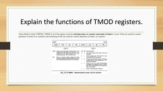
8051 Microcontroller Question
and Answers - 1
Explain the functions of TMOD registers.
Timer Mode Control (TMOD): TMOD is an 8-bit register used for selecting timer or counter and mode of timers. Lower 4-bits are used for control
operation of timer 0 or counter0, and remaining 4-bits are used for control operation of timer1 or counter1.
Write about register bank and stack.
• Register Banks in 8051
• A total of 32 bytes of RAM are set aside for the register banks and the
stack. These 32 bytes are divided into four register banks in which each bank
has 8 registers, R0–R7.
Explain the I/O port programming with the
help of LED interfacing.
• The four ports P0, P1, P2, and P3, each use 8 pins, making them 8-bit ports. Upon RESET, all the ports are
configured as inputs, ready to be used as input ports. When the first 0 is written to a port, it becomes an
output. To reconfigure it as an input, a 1 must be sent to a port.
• Dual Role of Port 0 and Port 2
• Dual role of Port 0 − Port 0 is also designated as AD0–AD7, as it can be used for both data and address
handling. While connecting an 8051 to external memory, Port 0 can provide both address and data. The 8051
microcontroller then multiplexes the input as address or data in order to save pins.
• Dual role of Port 2 − Besides working as I/O, Port P2 is also used to provide 16-bit address bus for
external memory along with Port 0. Port P2 is also designated as (A8– A15), while Port 0 provides the lower
8-bits via A0–A7. In other words, we can say that when an 8051 is connected to an external memory (ROM)
which can be maximum up to 64KB and this is possible by 16 bit address bus because we know 216 = 64KB.
Port2 is used for the upper 8-bit of the 16 bits address, and it cannot be used for I/O and this is the way any
Program code of external ROM is addressed.
Illustrate DC motor interfacing with 8051.

8051 Microcontroller -1.pptx

  • 1.
  • 2.
    Explain the functionsof TMOD registers. Timer Mode Control (TMOD): TMOD is an 8-bit register used for selecting timer or counter and mode of timers. Lower 4-bits are used for control operation of timer 0 or counter0, and remaining 4-bits are used for control operation of timer1 or counter1.
  • 3.
    Write about registerbank and stack. • Register Banks in 8051 • A total of 32 bytes of RAM are set aside for the register banks and the stack. These 32 bytes are divided into four register banks in which each bank has 8 registers, R0–R7.
  • 4.
    Explain the I/Oport programming with the help of LED interfacing. • The four ports P0, P1, P2, and P3, each use 8 pins, making them 8-bit ports. Upon RESET, all the ports are configured as inputs, ready to be used as input ports. When the first 0 is written to a port, it becomes an output. To reconfigure it as an input, a 1 must be sent to a port. • Dual Role of Port 0 and Port 2 • Dual role of Port 0 − Port 0 is also designated as AD0–AD7, as it can be used for both data and address handling. While connecting an 8051 to external memory, Port 0 can provide both address and data. The 8051 microcontroller then multiplexes the input as address or data in order to save pins. • Dual role of Port 2 − Besides working as I/O, Port P2 is also used to provide 16-bit address bus for external memory along with Port 0. Port P2 is also designated as (A8– A15), while Port 0 provides the lower 8-bits via A0–A7. In other words, we can say that when an 8051 is connected to an external memory (ROM) which can be maximum up to 64KB and this is possible by 16 bit address bus because we know 216 = 64KB. Port2 is used for the upper 8-bit of the 16 bits address, and it cannot be used for I/O and this is the way any Program code of external ROM is addressed.
  • 5.
    Illustrate DC motorinterfacing with 8051.