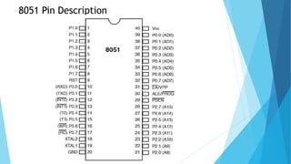
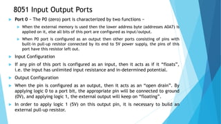
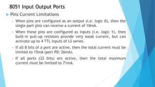
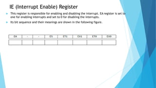
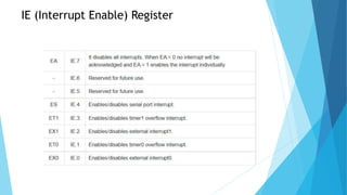
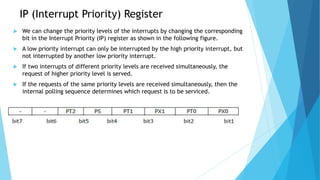
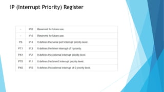
SlideShare a Scribd company logo
Microprocessor & Microcontroller
Unit 4: Introduction to 8051 Microcontroller
What is Microcontroller?
 A microcontroller is a small and low-cost microcomputer,
which is designed to perform the specific tasks of
embedded systems like displaying microwave’s
information, receiving remote signals, etc.
 The general microcontroller consists of the processor, the
memory (RAM, ROM, EPROM), Serial ports, peripherals
(timers, counters), etc.
Difference between Microprocessor and Microcontroller
Microprocessors Microcontrollers
It is used for big applications. It is used to execute a single task within an
application.
Microprocessor is the heart of computer system. It is the heart of the embedded system.
It is just a processor. Memory and I/O components
have to be having to be connected externally.
Microcontroller contains external processor along
with internal memory and I/O components.
Since I/O and memory connected externally, the
circuit becomes large.
Since I/O and memory present internally, the
circuit is small.
Can't be used in compact systems and hence
inefficient.
Can be used in compact systems and
microcontroller is an efficient technique.
Cost of entire system increases. Cost of entire system is low.
Power consumption is high. Power consumption is low.
Most of the microprocessors do not have power
saving modes.
Most of the microcontrollers have power saving
mode.
Difficult to replace. Easy to replace.
Mainly used in personal computers. Used mainly in washing machine, MP3 players.
Types of Microcontrollers
 Microcontrollers are divided into various categories based on memory,
architecture, bits and instruction sets.
Types of Microcontrollers
(Bit)
 Based on bit configuration, the microcontroller is further divided into three
categories.
 8-bit microcontroller − This type of microcontroller is used to execute
arithmetic and logical operations like addition, subtraction, multiplication
division, etc. For example, Intel 8031 and 8051 are 8 bits microcontroller.
 16-bit microcontroller − This type of microcontroller is used to perform
arithmetic and logical operations where higher accuracy and performance is
required. For example, Intel 8096 is a 16-bit microcontroller.
 32-bit microcontroller − This type of microcontroller is generally used in
automatically controlled appliances like automatic operational machines,
medical appliances, etc.
Types of Microcontrollers
(Memory)
 Based on the memory configuration, the microcontroller is further divided
into two categories.
 External memory microcontroller − This type of microcontroller is designed
in such a way that they do not have a program memory on the chip. Hence, it
is named as external memory microcontroller. For example: Intel 8031
microcontroller.
 Embedded memory microcontroller − This type of microcontroller is
designed in such a way that the microcontroller has all programs and data
memory, counters and timers, interrupts, I/O ports are embedded on the
chip. For example: Intel 8051 microcontroller.
Types of Microcontrollers
(Instruction Set)
 Based on the instruction set configuration, the microcontroller is
further divided into two categories.
 CISC − CISC stands for complex instruction set computer. It allows the
user to insert a single instruction as an alternative to many simple
instructions.
 RISC − RISC stands for Reduced Instruction Set Computers. It reduces
the operational time by shortening the clock cycle per instruction.
Applications of Microcontrollers
 Light sensing and controlling devices like LED.
 Temperature sensing and controlling devices like
microwave oven, chimneys.
 Fire detection and safety devices like Fire alarm.
 Measuring devices like Volt Meter.
8051 Microcontroller
 8051 microcontroller is designed by Intel in 1981.
 It is an 8-bit microcontroller.
 It is built with 40 pins DIP (dual inline package), 4kb of ROM storage
and 128 bytes of RAM storage, 2 16-bit timers.
 It consists of are four parallel 8-bit ports, which are programmable as
well as addressable as per the requirement.
 An on-chip crystal oscillator is integrated in the microcontroller
having crystal frequency of 12 MHz
Features of 8051 Microcontroller
 8-bit CPU through two Registers A & B.
 8K Bytes – Internal ROM and it is a flash memory that supports while
programming the system.
 256 Bytes – Internal RAM where the first RAM with 128 Bytes from 00H to 7FH is
once more separated into four banks through 8 registers in every bank,
addressable registers -16 bit & general-purpose registers – 80.
 The remaining 128 bytes of the RAM from 80H to FFH include Special Function
Registers (SFRs). These registers control various peripherals such as Serial Port,
Timers, all I/O Ports, etc.
 Interrupts like External-2 & Internal-3
 Oscillator & CLK Circuit.
 Control Registers like PCON, SCON, TMOD, TCON, IE, and IP.
 16-bit Timers or Counters -2 like T0 & T1.
 Program Counter – 16 bit & DPRT (Data Pointer).
 I/O Pins – 32 which are arranged like four ports such as P0, P1, P2 & P3.
 Stack Pointer (SP) – 8bit & PSW (Processor Status Word).
 Serial Data Tx & Rx for Full-Duplex Operation
Architecture of 8051 Microcontroller.
 the system bus connects all the support devices to the CPU.
 The system bus consists of an 8-bit data bus, a 16-bit address
bus and bus control signals.
 All other devices like program memory, ports, data memory,
serial interface, interrupt control, timers, and the CPU are all
interfaced together through the system bus.
 The 8051 contains Boolean processor, full duplex serial port and
power saving circuitry in addition to essential components such
as 8-bit CPU, RAM, ROM/EPROM/OTPROM, timer/counter and
parallel I/O lines.
8051 Pin Description
 Pins 1 to 8 − These pins are known as Port 1. This port doesn’t serve any other functions.
It is internally pulled up, bi-directional I/O port.
 Pin 9 − It is a RESET pin, which is used to reset the microcontroller to its initial values.
 Pins 10 to 17 − These pins are known as Port 3. This port serves some functions like
interrupts, timer input, control signals, serial communication signals RxD and TxD, etc.
 Pins 18 & 19 − These pins are used for interfacing an external crystal to get the system
clock.
 Pin 20 − This pin provides the power supply to the circuit.
 Pins 21 to 28 − These pins are known as Port 2. It serves as I/O port. Higher order address
bus signals are also multiplexed using this port.
 Pin 29 − This is PSEN pin which stands for Program Store Enable. It is used to read a signal
from the external program memory.
 Pin 30 − This is EA pin which stands for External Access input. It is used to enable/disable
the external memory interfacing.
 Pin 31 − This is ALE pin which stands for Address Latch Enable. It is used to demultiplex
the address-data signal of port.
 Pins 32 to 39 − These pins are known as Port 0. It serves as I/O port. Lower order address
and data bus signals are multiplexed using this port.
 Pin 40 − This pin is used to provide power supply to the circuit.
8051 Input Output Ports
 8051 microcontrollers have 4 I/O ports each of 8-bit, which can
be configured as input or output.
 Hence, total 32 input/output pins allow the microcontroller to be
connected with the peripheral devices.
 Pin configuration, i.e. the pin can be configured as 1 for input
and 0 for output as per the logic state.
 Input/Output (I/O) pin − All the circuits within the microcontroller must be
connected to one of its pins except P0 port because it does not have pull-
up resistors built-in.
 Input pin − Logic 1 is applied to a bit of the P register. The output FE
transistor is turned off and the other pin remains connected to the power
supply voltage over a pull-up resistor of high resistance.
8051 Input Output Ports
 Port 0 − The P0 (zero) port is characterized by two functions −
 When the external memory is used then the lower address byte (addresses A0A7) is
applied on it, else all bits of this port are configured as input/output.
 When P0 port is configured as an output then other ports consisting of pins with
built-in pull-up resistor connected by its end to 5V power supply, the pins of this
port have this resistor left out.
 Input Configuration
 If any pin of this port is configured as an input, then it acts as if it “floats”,
i.e. the input has unlimited input resistance and in-determined potential.
 Output Configuration
 When the pin is configured as an output, then it acts as an “open drain”. By
applying logic 0 to a port bit, the appropriate pin will be connected to ground
(0V), and applying logic 1, the external output will keep on “floating”.
 In order to apply logic 1 (5V) on this output pin, it is necessary to build an
external pull-up resistor.
8051 Input Output Ports
 Port 1
 P1 is a true I/O port as it doesn’t have any alternative functions as in P0,
but this port can be configured as general I/O only. It has a built-in pull-up
resistor and is completely compatible with TTL circuits.
 Port 2
 P2 is similar to P0 when the external memory is used. Pins of this port
occupy addresses intended for the external memory chip. This port can be
used for higher address byte with addresses A8-A15. When no memory is
added then this port can be used as a general input/output port similar to
Port 1.
 Port 3
 In this port, functions are similar to other ports except that the logic 1
must be applied to appropriate bit of the P3 register.
8051 Input Output Ports
 Pins Current Limitations
 When pins are configured as an output (i.e. logic 0), then the
single port pins can receive a current of 10mA.
 When these pins are configured as inputs (i.e. logic 1), then
built-in pull-up resistors provide very weak current, but can
activate up to 4 TTL inputs of LS series.
 If all 8 bits of a port are active, then the total current must be
limited to 15mA (port P0: 26mA).
 If all ports (32 bits) are active, then the total maximum
current must be limited to 71mA.
8051 Interrupts
 Interrupts are the events that temporarily suspend the main
program, pass the control to the external sources and execute
their task.
 It then passes the control to the main program where it had left
off.
 8051 has 5 interrupt signals, i.e. INT0, TFO, INT1, TF1, RI/TI.
 Each interrupt can be enabled or disabled by setting bits of the
IE register and the whole interrupt system can be disabled by
clearing the EA bit of the same register.
IE (Interrupt Enable) Register
 This register is responsible for enabling and disabling the interrupt. EA register is set to
one for enabling interrupts and set to 0 for disabling the interrupts.
 Its bit sequence and their meanings are shown in the following figure.
IE (Interrupt Enable) Register
IP (Interrupt Priority) Register
 We can change the priority levels of the interrupts by changing the corresponding
bit in the Interrupt Priority (IP) register as shown in the following figure.
 A low priority interrupt can only be interrupted by the high priority interrupt, but
not interrupted by another low priority interrupt.
 If two interrupts of different priority levels are received simultaneously, the
request of higher priority level is served.
 If the requests of the same priority levels are received simultaneously, then the
internal polling sequence determines which request is to be serviced.
IP (Interrupt Priority) Register
TCON Register
 TCON register specifies the type of external interrupt to
the microcontroller.

More Related Content

Similar to Microcontroller (1).pptx

8051 microcontroller
8051 microcontroller8051 microcontroller
8051 microcontroller
Souvik Dutta
 
8051 microcontroller
8051 microcontroller 8051 microcontroller
8051 microcontroller
nitugatkal
 
Microcontroller (8051) by K. Vijay Kumar
Microcontroller (8051) by K. Vijay KumarMicrocontroller (8051) by K. Vijay Kumar
Microcontroller (8051) by K. Vijay Kumar
Vijay Kumar
 
8051 microcontroller by K. Vijay Kumar
8051 microcontroller by K. Vijay Kumar8051 microcontroller by K. Vijay Kumar
8051 microcontroller by K. Vijay Kumar
Vijay Kumar
 
SYBSC IT SEM IV EMBEDDED SYSTEMS UNIT III The 8051 Microcontrollers
SYBSC IT SEM IV EMBEDDED SYSTEMS UNIT III  The 8051 MicrocontrollersSYBSC IT SEM IV EMBEDDED SYSTEMS UNIT III  The 8051 Microcontrollers
SYBSC IT SEM IV EMBEDDED SYSTEMS UNIT III The 8051 Microcontrollers
Arti Parab Academics
 
Advanced Microprocessor 6.pptx
Advanced Microprocessor 6.pptxAdvanced Microprocessor 6.pptx
Advanced Microprocessor 6.pptx
ShanDimantha1
 
Embedded systems ppt i
Embedded systems ppt iEmbedded systems ppt i
Embedded systems ppt i
anishgoel
 
8051 microcontroller Microcontroller _2024.pptx
8051 microcontroller Microcontroller _2024.pptx8051 microcontroller Microcontroller _2024.pptx
8051 microcontroller Microcontroller _2024.pptx
rohithansaliya2
 
Ch3 ppt
Ch3 pptCh3 ppt
Ch3 ppt
wasz123
 
janakiraman egsp collage I msc 4 unit
janakiraman egsp collage  I msc 4 unitjanakiraman egsp collage  I msc 4 unit
janakiraman egsp collage I msc 4 unit
janakiramang6
 
janakiraman I msc 4 unit
janakiraman I msc 4 unitjanakiraman I msc 4 unit
janakiraman I msc 4 unit
janakiramang6
 
Microcontroller-8051.ppt
Microcontroller-8051.pptMicrocontroller-8051.ppt
Microcontroller-8051.ppt
KalaiSelvan911913
 
Embedded System Microcontroller 8051
Embedded System Microcontroller 8051Embedded System Microcontroller 8051
Embedded System Microcontroller 8051
ShawnIslam20150022
 
POA_Unit 5.pptx
POA_Unit 5.pptxPOA_Unit 5.pptx
POA_Unit 5.pptx
GAURAVWANI11
 
8051 Microcontroller
8051 Microcontroller8051 Microcontroller
8051 Microcontroller
thokalpv
 
8051 book
8051 book8051 book
8051 Architecture and PIN Configuration.pdf
8051 Architecture and PIN Configuration.pdf8051 Architecture and PIN Configuration.pdf
8051 Architecture and PIN Configuration.pdf
Srikrishna Thota
 
Embeded system
Embeded systemEmbeded system
Embeded system
SUneel Gupta
 
89s52 2
89s52 289s52 2
Fundamentals of Microcontroller 8051 by Dr. Jogade S M, Assistant Professor, ...
Fundamentals of Microcontroller 8051 by Dr. Jogade S M, Assistant Professor, ...Fundamentals of Microcontroller 8051 by Dr. Jogade S M, Assistant Professor, ...
Fundamentals of Microcontroller 8051 by Dr. Jogade S M, Assistant Professor, ...
sangeeta jogade
 

Similar to Microcontroller (1).pptx (20)

8051 microcontroller
8051 microcontroller8051 microcontroller
8051 microcontroller
 
8051 microcontroller
8051 microcontroller 8051 microcontroller
8051 microcontroller
 
Microcontroller (8051) by K. Vijay Kumar
Microcontroller (8051) by K. Vijay KumarMicrocontroller (8051) by K. Vijay Kumar
Microcontroller (8051) by K. Vijay Kumar
 
8051 microcontroller by K. Vijay Kumar
8051 microcontroller by K. Vijay Kumar8051 microcontroller by K. Vijay Kumar
8051 microcontroller by K. Vijay Kumar
 
SYBSC IT SEM IV EMBEDDED SYSTEMS UNIT III The 8051 Microcontrollers
SYBSC IT SEM IV EMBEDDED SYSTEMS UNIT III  The 8051 MicrocontrollersSYBSC IT SEM IV EMBEDDED SYSTEMS UNIT III  The 8051 Microcontrollers
SYBSC IT SEM IV EMBEDDED SYSTEMS UNIT III The 8051 Microcontrollers
 
Advanced Microprocessor 6.pptx
Advanced Microprocessor 6.pptxAdvanced Microprocessor 6.pptx
Advanced Microprocessor 6.pptx
 
Embedded systems ppt i
Embedded systems ppt iEmbedded systems ppt i
Embedded systems ppt i
 
8051 microcontroller Microcontroller _2024.pptx
8051 microcontroller Microcontroller _2024.pptx8051 microcontroller Microcontroller _2024.pptx
8051 microcontroller Microcontroller _2024.pptx
 
Ch3 ppt
Ch3 pptCh3 ppt
Ch3 ppt
 
janakiraman egsp collage I msc 4 unit
janakiraman egsp collage  I msc 4 unitjanakiraman egsp collage  I msc 4 unit
janakiraman egsp collage I msc 4 unit
 
janakiraman I msc 4 unit
janakiraman I msc 4 unitjanakiraman I msc 4 unit
janakiraman I msc 4 unit
 
Microcontroller-8051.ppt
Microcontroller-8051.pptMicrocontroller-8051.ppt
Microcontroller-8051.ppt
 
Embedded System Microcontroller 8051
Embedded System Microcontroller 8051Embedded System Microcontroller 8051
Embedded System Microcontroller 8051
 
POA_Unit 5.pptx
POA_Unit 5.pptxPOA_Unit 5.pptx
POA_Unit 5.pptx
 
8051 Microcontroller
8051 Microcontroller8051 Microcontroller
8051 Microcontroller
 
8051 book
8051 book8051 book
8051 book
 
8051 Architecture and PIN Configuration.pdf
8051 Architecture and PIN Configuration.pdf8051 Architecture and PIN Configuration.pdf
8051 Architecture and PIN Configuration.pdf
 
Embeded system
Embeded systemEmbeded system
Embeded system
 
89s52 2
89s52 289s52 2
89s52 2
 
Fundamentals of Microcontroller 8051 by Dr. Jogade S M, Assistant Professor, ...
Fundamentals of Microcontroller 8051 by Dr. Jogade S M, Assistant Professor, ...Fundamentals of Microcontroller 8051 by Dr. Jogade S M, Assistant Professor, ...
Fundamentals of Microcontroller 8051 by Dr. Jogade S M, Assistant Professor, ...
 

Recently uploaded

Iron and Steel Technology Roadmap - Towards more sustainable steelmaking.pdf
Iron and Steel Technology Roadmap - Towards more sustainable steelmaking.pdfIron and Steel Technology Roadmap - Towards more sustainable steelmaking.pdf
Iron and Steel Technology Roadmap - Towards more sustainable steelmaking.pdf
RadiNasr
 
哪里办理(csu毕业证书)查尔斯特大学毕业证硕士学历原版一模一样
哪里办理(csu毕业证书)查尔斯特大学毕业证硕士学历原版一模一样哪里办理(csu毕业证书)查尔斯特大学毕业证硕士学历原版一模一样
哪里办理(csu毕业证书)查尔斯特大学毕业证硕士学历原版一模一样
insn4465
 
Low power architecture of logic gates using adiabatic techniques
Low power architecture of logic gates using adiabatic techniquesLow power architecture of logic gates using adiabatic techniques
Low power architecture of logic gates using adiabatic techniques
nooriasukmaningtyas
 
sieving analysis and results interpretation
sieving analysis and results interpretationsieving analysis and results interpretation
sieving analysis and results interpretation
ssuser36d3051
 
Recycled Concrete Aggregate in Construction Part III
Recycled Concrete Aggregate in Construction Part IIIRecycled Concrete Aggregate in Construction Part III
Recycled Concrete Aggregate in Construction Part III
Aditya Rajan Patra
 
ACEP Magazine edition 4th launched on 05.06.2024
ACEP Magazine edition 4th launched on 05.06.2024ACEP Magazine edition 4th launched on 05.06.2024
ACEP Magazine edition 4th launched on 05.06.2024
Rahul
 
Technical Drawings introduction to drawing of prisms
Technical Drawings introduction to drawing of prismsTechnical Drawings introduction to drawing of prisms
Technical Drawings introduction to drawing of prisms
heavyhaig
 
spirit beverages ppt without graphics.pptx
spirit beverages ppt without graphics.pptxspirit beverages ppt without graphics.pptx
spirit beverages ppt without graphics.pptx
Madan Karki
 
Heat Resistant Concrete Presentation ppt
Heat Resistant Concrete Presentation pptHeat Resistant Concrete Presentation ppt
Heat Resistant Concrete Presentation ppt
mamunhossenbd75
 
Understanding Inductive Bias in Machine Learning
Understanding Inductive Bias in Machine LearningUnderstanding Inductive Bias in Machine Learning
Understanding Inductive Bias in Machine Learning
SUTEJAS
 
ML Based Model for NIDS MSc Updated Presentation.v2.pptx
ML Based Model for NIDS MSc Updated Presentation.v2.pptxML Based Model for NIDS MSc Updated Presentation.v2.pptx
ML Based Model for NIDS MSc Updated Presentation.v2.pptx
JamalHussainArman
 
bank management system in java and mysql report1.pdf
bank management system in java and mysql report1.pdfbank management system in java and mysql report1.pdf
bank management system in java and mysql report1.pdf
Divyam548318
 
IEEE Aerospace and Electronic Systems Society as a Graduate Student Member
IEEE Aerospace and Electronic Systems Society as a Graduate Student MemberIEEE Aerospace and Electronic Systems Society as a Graduate Student Member
IEEE Aerospace and Electronic Systems Society as a Graduate Student Member
VICTOR MAESTRE RAMIREZ
 
New techniques for characterising damage in rock slopes.pdf
New techniques for characterising damage in rock slopes.pdfNew techniques for characterising damage in rock slopes.pdf
New techniques for characterising damage in rock slopes.pdf
wisnuprabawa3
 
Literature Review Basics and Understanding Reference Management.pptx
Literature Review Basics and Understanding Reference Management.pptxLiterature Review Basics and Understanding Reference Management.pptx
Literature Review Basics and Understanding Reference Management.pptx
Dr Ramhari Poudyal
 
DfMAy 2024 - key insights and contributions
DfMAy 2024 - key insights and contributionsDfMAy 2024 - key insights and contributions
DfMAy 2024 - key insights and contributions
gestioneergodomus
 
132/33KV substation case study Presentation
132/33KV substation case study Presentation132/33KV substation case study Presentation
132/33KV substation case study Presentation
kandramariana6
 
22CYT12-Unit-V-E Waste and its Management.ppt
22CYT12-Unit-V-E Waste and its Management.ppt22CYT12-Unit-V-E Waste and its Management.ppt
22CYT12-Unit-V-E Waste and its Management.ppt
KrishnaveniKrishnara1
 
Swimming pool mechanical components design.pptx
Swimming pool  mechanical components design.pptxSwimming pool  mechanical components design.pptx
Swimming pool mechanical components design.pptx
yokeleetan1
 
Manufacturing Process of molasses based distillery ppt.pptx
Manufacturing Process of molasses based distillery ppt.pptxManufacturing Process of molasses based distillery ppt.pptx
Manufacturing Process of molasses based distillery ppt.pptx
Madan Karki
 

Recently uploaded (20)

Iron and Steel Technology Roadmap - Towards more sustainable steelmaking.pdf
Iron and Steel Technology Roadmap - Towards more sustainable steelmaking.pdfIron and Steel Technology Roadmap - Towards more sustainable steelmaking.pdf
Iron and Steel Technology Roadmap - Towards more sustainable steelmaking.pdf
 
哪里办理(csu毕业证书)查尔斯特大学毕业证硕士学历原版一模一样
哪里办理(csu毕业证书)查尔斯特大学毕业证硕士学历原版一模一样哪里办理(csu毕业证书)查尔斯特大学毕业证硕士学历原版一模一样
哪里办理(csu毕业证书)查尔斯特大学毕业证硕士学历原版一模一样
 
Low power architecture of logic gates using adiabatic techniques
Low power architecture of logic gates using adiabatic techniquesLow power architecture of logic gates using adiabatic techniques
Low power architecture of logic gates using adiabatic techniques
 
sieving analysis and results interpretation
sieving analysis and results interpretationsieving analysis and results interpretation
sieving analysis and results interpretation
 
Recycled Concrete Aggregate in Construction Part III
Recycled Concrete Aggregate in Construction Part IIIRecycled Concrete Aggregate in Construction Part III
Recycled Concrete Aggregate in Construction Part III
 
ACEP Magazine edition 4th launched on 05.06.2024
ACEP Magazine edition 4th launched on 05.06.2024ACEP Magazine edition 4th launched on 05.06.2024
ACEP Magazine edition 4th launched on 05.06.2024
 
Technical Drawings introduction to drawing of prisms
Technical Drawings introduction to drawing of prismsTechnical Drawings introduction to drawing of prisms
Technical Drawings introduction to drawing of prisms
 
spirit beverages ppt without graphics.pptx
spirit beverages ppt without graphics.pptxspirit beverages ppt without graphics.pptx
spirit beverages ppt without graphics.pptx
 
Heat Resistant Concrete Presentation ppt
Heat Resistant Concrete Presentation pptHeat Resistant Concrete Presentation ppt
Heat Resistant Concrete Presentation ppt
 
Understanding Inductive Bias in Machine Learning
Understanding Inductive Bias in Machine LearningUnderstanding Inductive Bias in Machine Learning
Understanding Inductive Bias in Machine Learning
 
ML Based Model for NIDS MSc Updated Presentation.v2.pptx
ML Based Model for NIDS MSc Updated Presentation.v2.pptxML Based Model for NIDS MSc Updated Presentation.v2.pptx
ML Based Model for NIDS MSc Updated Presentation.v2.pptx
 
bank management system in java and mysql report1.pdf
bank management system in java and mysql report1.pdfbank management system in java and mysql report1.pdf
bank management system in java and mysql report1.pdf
 
IEEE Aerospace and Electronic Systems Society as a Graduate Student Member
IEEE Aerospace and Electronic Systems Society as a Graduate Student MemberIEEE Aerospace and Electronic Systems Society as a Graduate Student Member
IEEE Aerospace and Electronic Systems Society as a Graduate Student Member
 
New techniques for characterising damage in rock slopes.pdf
New techniques for characterising damage in rock slopes.pdfNew techniques for characterising damage in rock slopes.pdf
New techniques for characterising damage in rock slopes.pdf
 
Literature Review Basics and Understanding Reference Management.pptx
Literature Review Basics and Understanding Reference Management.pptxLiterature Review Basics and Understanding Reference Management.pptx
Literature Review Basics and Understanding Reference Management.pptx
 
DfMAy 2024 - key insights and contributions
DfMAy 2024 - key insights and contributionsDfMAy 2024 - key insights and contributions
DfMAy 2024 - key insights and contributions
 
132/33KV substation case study Presentation
132/33KV substation case study Presentation132/33KV substation case study Presentation
132/33KV substation case study Presentation
 
22CYT12-Unit-V-E Waste and its Management.ppt
22CYT12-Unit-V-E Waste and its Management.ppt22CYT12-Unit-V-E Waste and its Management.ppt
22CYT12-Unit-V-E Waste and its Management.ppt
 
Swimming pool mechanical components design.pptx
Swimming pool  mechanical components design.pptxSwimming pool  mechanical components design.pptx
Swimming pool mechanical components design.pptx
 
Manufacturing Process of molasses based distillery ppt.pptx
Manufacturing Process of molasses based distillery ppt.pptxManufacturing Process of molasses based distillery ppt.pptx
Manufacturing Process of molasses based distillery ppt.pptx
 

Microcontroller (1).pptx

  • 1. Microprocessor & Microcontroller Unit 4: Introduction to 8051 Microcontroller
  • 2. What is Microcontroller?  A microcontroller is a small and low-cost microcomputer, which is designed to perform the specific tasks of embedded systems like displaying microwave’s information, receiving remote signals, etc.  The general microcontroller consists of the processor, the memory (RAM, ROM, EPROM), Serial ports, peripherals (timers, counters), etc.
  • 3. Difference between Microprocessor and Microcontroller Microprocessors Microcontrollers It is used for big applications. It is used to execute a single task within an application. Microprocessor is the heart of computer system. It is the heart of the embedded system. It is just a processor. Memory and I/O components have to be having to be connected externally. Microcontroller contains external processor along with internal memory and I/O components. Since I/O and memory connected externally, the circuit becomes large. Since I/O and memory present internally, the circuit is small. Can't be used in compact systems and hence inefficient. Can be used in compact systems and microcontroller is an efficient technique. Cost of entire system increases. Cost of entire system is low. Power consumption is high. Power consumption is low. Most of the microprocessors do not have power saving modes. Most of the microcontrollers have power saving mode. Difficult to replace. Easy to replace. Mainly used in personal computers. Used mainly in washing machine, MP3 players.
  • 4. Types of Microcontrollers  Microcontrollers are divided into various categories based on memory, architecture, bits and instruction sets.
  • 5. Types of Microcontrollers (Bit)  Based on bit configuration, the microcontroller is further divided into three categories.  8-bit microcontroller − This type of microcontroller is used to execute arithmetic and logical operations like addition, subtraction, multiplication division, etc. For example, Intel 8031 and 8051 are 8 bits microcontroller.  16-bit microcontroller − This type of microcontroller is used to perform arithmetic and logical operations where higher accuracy and performance is required. For example, Intel 8096 is a 16-bit microcontroller.  32-bit microcontroller − This type of microcontroller is generally used in automatically controlled appliances like automatic operational machines, medical appliances, etc.
  • 6. Types of Microcontrollers (Memory)  Based on the memory configuration, the microcontroller is further divided into two categories.  External memory microcontroller − This type of microcontroller is designed in such a way that they do not have a program memory on the chip. Hence, it is named as external memory microcontroller. For example: Intel 8031 microcontroller.  Embedded memory microcontroller − This type of microcontroller is designed in such a way that the microcontroller has all programs and data memory, counters and timers, interrupts, I/O ports are embedded on the chip. For example: Intel 8051 microcontroller.
  • 7. Types of Microcontrollers (Instruction Set)  Based on the instruction set configuration, the microcontroller is further divided into two categories.  CISC − CISC stands for complex instruction set computer. It allows the user to insert a single instruction as an alternative to many simple instructions.  RISC − RISC stands for Reduced Instruction Set Computers. It reduces the operational time by shortening the clock cycle per instruction.
  • 8. Applications of Microcontrollers  Light sensing and controlling devices like LED.  Temperature sensing and controlling devices like microwave oven, chimneys.  Fire detection and safety devices like Fire alarm.  Measuring devices like Volt Meter.
  • 9. 8051 Microcontroller  8051 microcontroller is designed by Intel in 1981.  It is an 8-bit microcontroller.  It is built with 40 pins DIP (dual inline package), 4kb of ROM storage and 128 bytes of RAM storage, 2 16-bit timers.  It consists of are four parallel 8-bit ports, which are programmable as well as addressable as per the requirement.  An on-chip crystal oscillator is integrated in the microcontroller having crystal frequency of 12 MHz
  • 10. Features of 8051 Microcontroller  8-bit CPU through two Registers A & B.  8K Bytes – Internal ROM and it is a flash memory that supports while programming the system.  256 Bytes – Internal RAM where the first RAM with 128 Bytes from 00H to 7FH is once more separated into four banks through 8 registers in every bank, addressable registers -16 bit & general-purpose registers – 80.  The remaining 128 bytes of the RAM from 80H to FFH include Special Function Registers (SFRs). These registers control various peripherals such as Serial Port, Timers, all I/O Ports, etc.  Interrupts like External-2 & Internal-3  Oscillator & CLK Circuit.  Control Registers like PCON, SCON, TMOD, TCON, IE, and IP.  16-bit Timers or Counters -2 like T0 & T1.  Program Counter – 16 bit & DPRT (Data Pointer).  I/O Pins – 32 which are arranged like four ports such as P0, P1, P2 & P3.  Stack Pointer (SP) – 8bit & PSW (Processor Status Word).  Serial Data Tx & Rx for Full-Duplex Operation
  • 11. Architecture of 8051 Microcontroller.
  • 12. Architecture of 8051 Microcontroller.  the system bus connects all the support devices to the CPU.  The system bus consists of an 8-bit data bus, a 16-bit address bus and bus control signals.  All other devices like program memory, ports, data memory, serial interface, interrupt control, timers, and the CPU are all interfaced together through the system bus.  The 8051 contains Boolean processor, full duplex serial port and power saving circuitry in addition to essential components such as 8-bit CPU, RAM, ROM/EPROM/OTPROM, timer/counter and parallel I/O lines.
  • 14. 8051 Pin Description  Pins 1 to 8 − These pins are known as Port 1. This port doesn’t serve any other functions. It is internally pulled up, bi-directional I/O port.  Pin 9 − It is a RESET pin, which is used to reset the microcontroller to its initial values.  Pins 10 to 17 − These pins are known as Port 3. This port serves some functions like interrupts, timer input, control signals, serial communication signals RxD and TxD, etc.  Pins 18 & 19 − These pins are used for interfacing an external crystal to get the system clock.  Pin 20 − This pin provides the power supply to the circuit.  Pins 21 to 28 − These pins are known as Port 2. It serves as I/O port. Higher order address bus signals are also multiplexed using this port.  Pin 29 − This is PSEN pin which stands for Program Store Enable. It is used to read a signal from the external program memory.  Pin 30 − This is EA pin which stands for External Access input. It is used to enable/disable the external memory interfacing.  Pin 31 − This is ALE pin which stands for Address Latch Enable. It is used to demultiplex the address-data signal of port.  Pins 32 to 39 − These pins are known as Port 0. It serves as I/O port. Lower order address and data bus signals are multiplexed using this port.  Pin 40 − This pin is used to provide power supply to the circuit.
  • 15. 8051 Input Output Ports  8051 microcontrollers have 4 I/O ports each of 8-bit, which can be configured as input or output.  Hence, total 32 input/output pins allow the microcontroller to be connected with the peripheral devices.  Pin configuration, i.e. the pin can be configured as 1 for input and 0 for output as per the logic state.  Input/Output (I/O) pin − All the circuits within the microcontroller must be connected to one of its pins except P0 port because it does not have pull- up resistors built-in.  Input pin − Logic 1 is applied to a bit of the P register. The output FE transistor is turned off and the other pin remains connected to the power supply voltage over a pull-up resistor of high resistance.
  • 16. 8051 Input Output Ports  Port 0 − The P0 (zero) port is characterized by two functions −  When the external memory is used then the lower address byte (addresses A0A7) is applied on it, else all bits of this port are configured as input/output.  When P0 port is configured as an output then other ports consisting of pins with built-in pull-up resistor connected by its end to 5V power supply, the pins of this port have this resistor left out.  Input Configuration  If any pin of this port is configured as an input, then it acts as if it “floats”, i.e. the input has unlimited input resistance and in-determined potential.  Output Configuration  When the pin is configured as an output, then it acts as an “open drain”. By applying logic 0 to a port bit, the appropriate pin will be connected to ground (0V), and applying logic 1, the external output will keep on “floating”.  In order to apply logic 1 (5V) on this output pin, it is necessary to build an external pull-up resistor.
  • 17. 8051 Input Output Ports  Port 1  P1 is a true I/O port as it doesn’t have any alternative functions as in P0, but this port can be configured as general I/O only. It has a built-in pull-up resistor and is completely compatible with TTL circuits.  Port 2  P2 is similar to P0 when the external memory is used. Pins of this port occupy addresses intended for the external memory chip. This port can be used for higher address byte with addresses A8-A15. When no memory is added then this port can be used as a general input/output port similar to Port 1.  Port 3  In this port, functions are similar to other ports except that the logic 1 must be applied to appropriate bit of the P3 register.
  • 18. 8051 Input Output Ports  Pins Current Limitations  When pins are configured as an output (i.e. logic 0), then the single port pins can receive a current of 10mA.  When these pins are configured as inputs (i.e. logic 1), then built-in pull-up resistors provide very weak current, but can activate up to 4 TTL inputs of LS series.  If all 8 bits of a port are active, then the total current must be limited to 15mA (port P0: 26mA).  If all ports (32 bits) are active, then the total maximum current must be limited to 71mA.
  • 19. 8051 Interrupts  Interrupts are the events that temporarily suspend the main program, pass the control to the external sources and execute their task.  It then passes the control to the main program where it had left off.  8051 has 5 interrupt signals, i.e. INT0, TFO, INT1, TF1, RI/TI.  Each interrupt can be enabled or disabled by setting bits of the IE register and the whole interrupt system can be disabled by clearing the EA bit of the same register.
  • 20. IE (Interrupt Enable) Register  This register is responsible for enabling and disabling the interrupt. EA register is set to one for enabling interrupts and set to 0 for disabling the interrupts.  Its bit sequence and their meanings are shown in the following figure.
  • 22. IP (Interrupt Priority) Register  We can change the priority levels of the interrupts by changing the corresponding bit in the Interrupt Priority (IP) register as shown in the following figure.  A low priority interrupt can only be interrupted by the high priority interrupt, but not interrupted by another low priority interrupt.  If two interrupts of different priority levels are received simultaneously, the request of higher priority level is served.  If the requests of the same priority levels are received simultaneously, then the internal polling sequence determines which request is to be serviced.
  • 24. TCON Register  TCON register specifies the type of external interrupt to the microcontroller.