This document introduces digital image processing (DIP), defining its scope, historical background, and its various applications in the field of image technology. It explains the distinction between analog and digital images, the evolution of DIP technology, and highlights multiple imaging techniques such as gamma ray, x-ray, ultraviolet, infrared, microwave, and radio imaging used in medical and astronomical contexts. Additionally, it outlines the components of a DIP system and provides an overview of the book's structure.
Introduction to Digital Image Processing (DIP), its objectives, scope, historical background, and principal approaches.
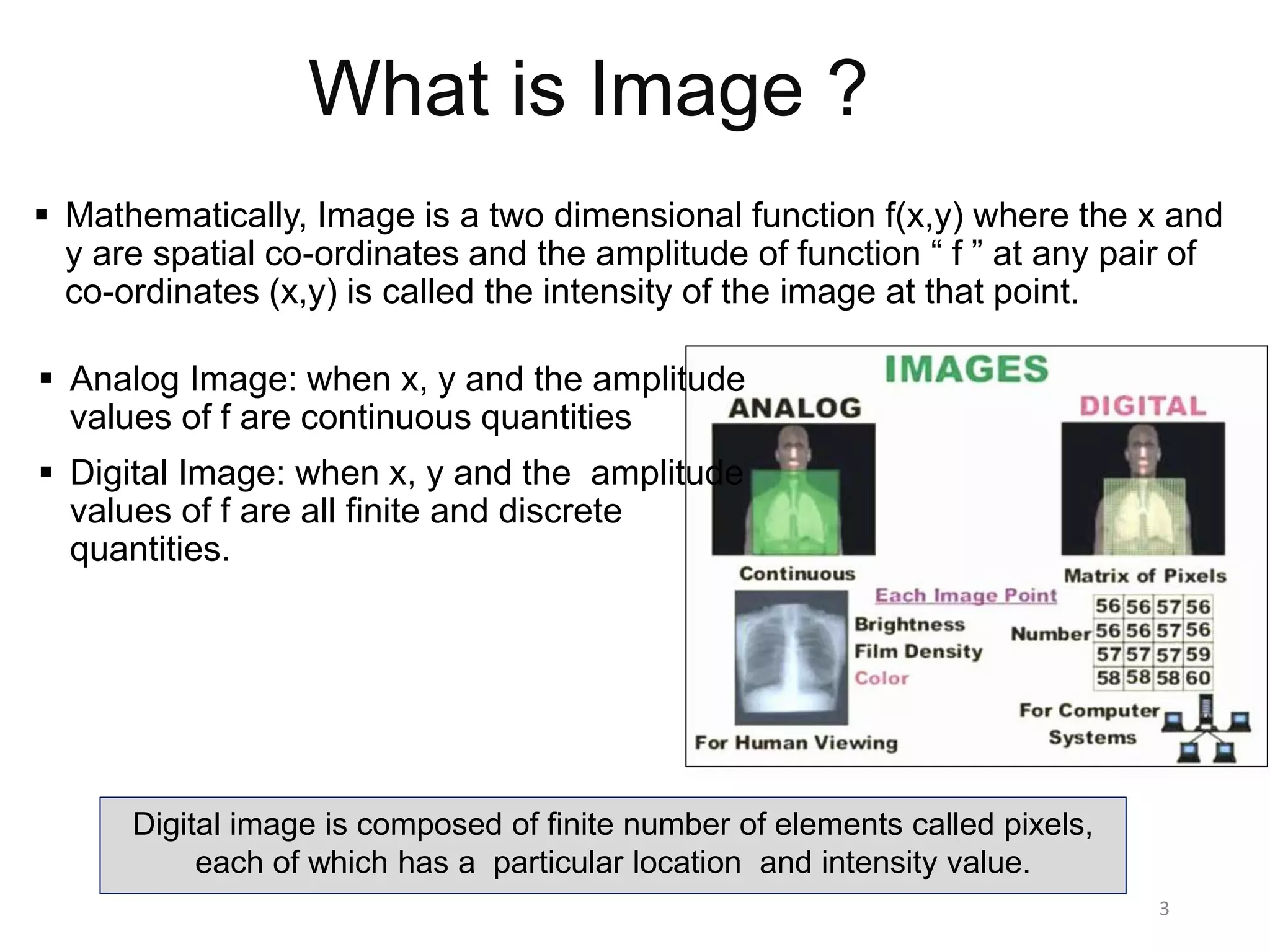
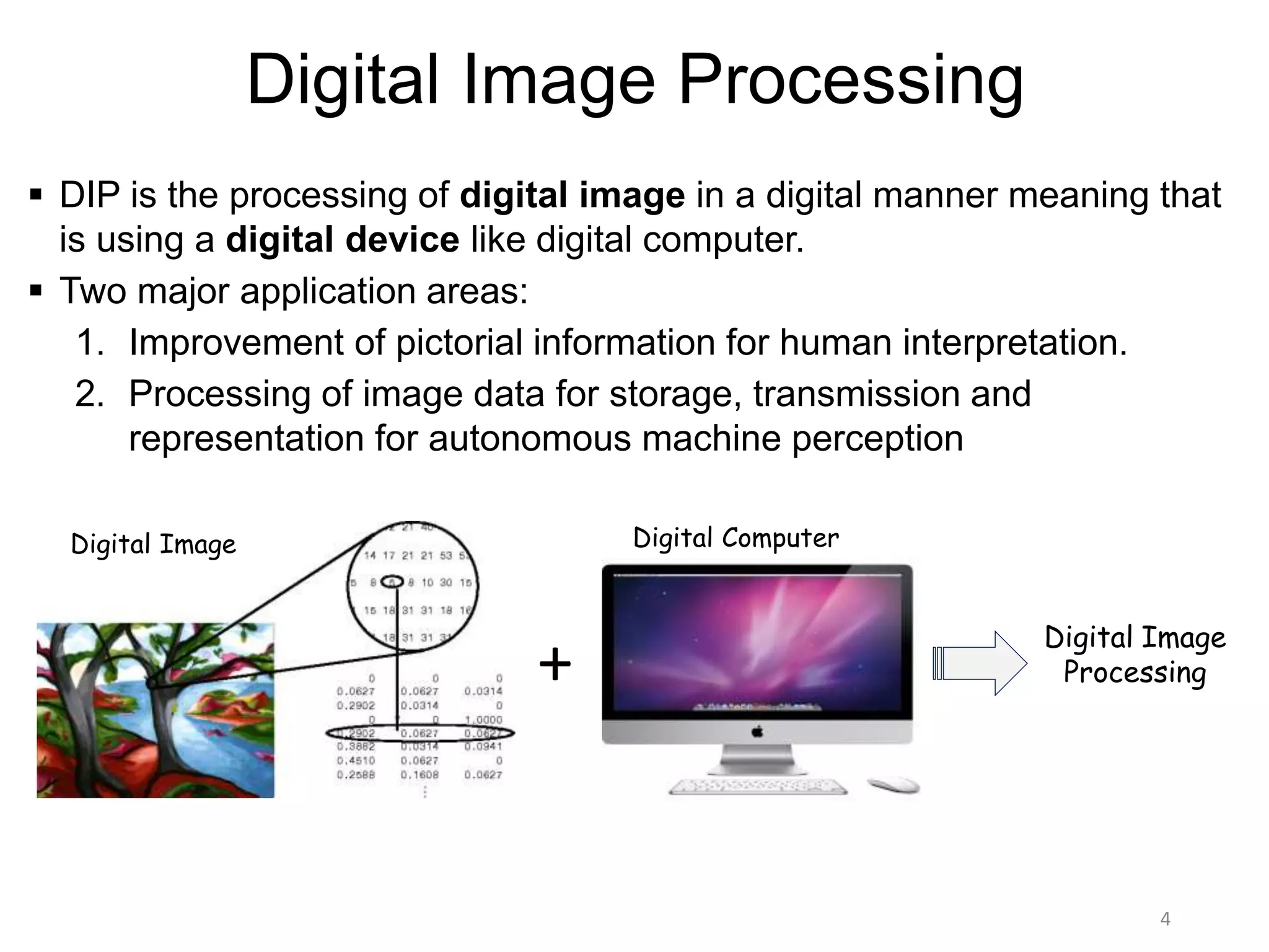
Definition of image as a function, distinction between analog and digital images. Introduction to digital image processing and its application for improvement and machine perception.
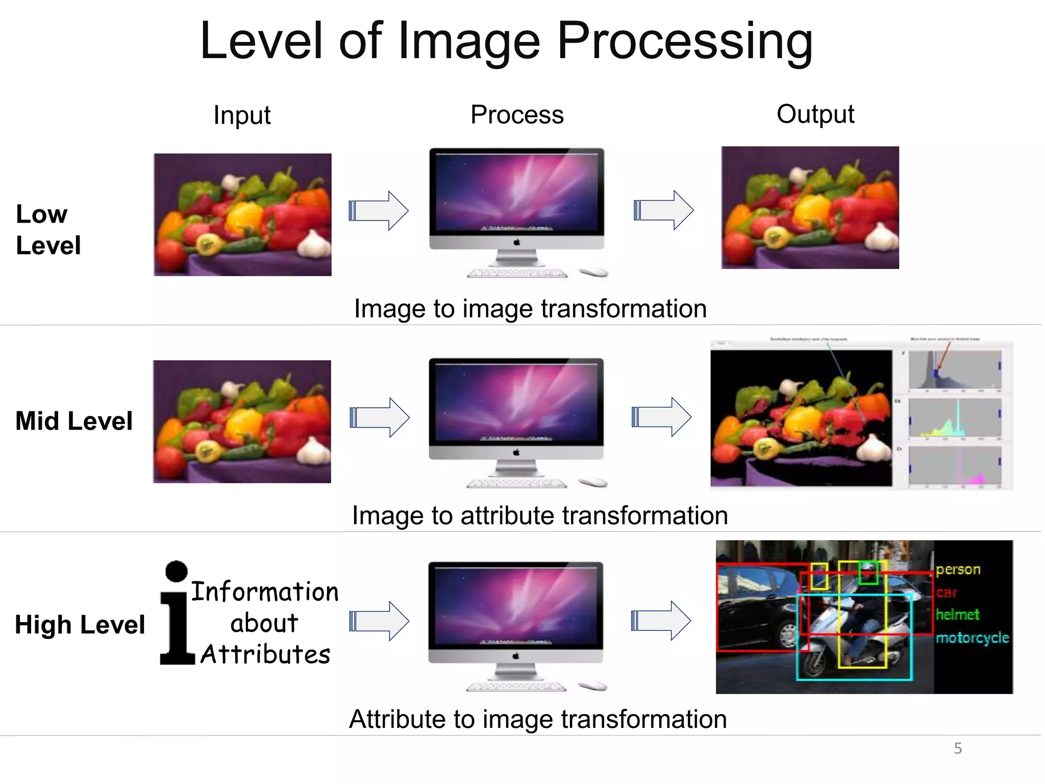
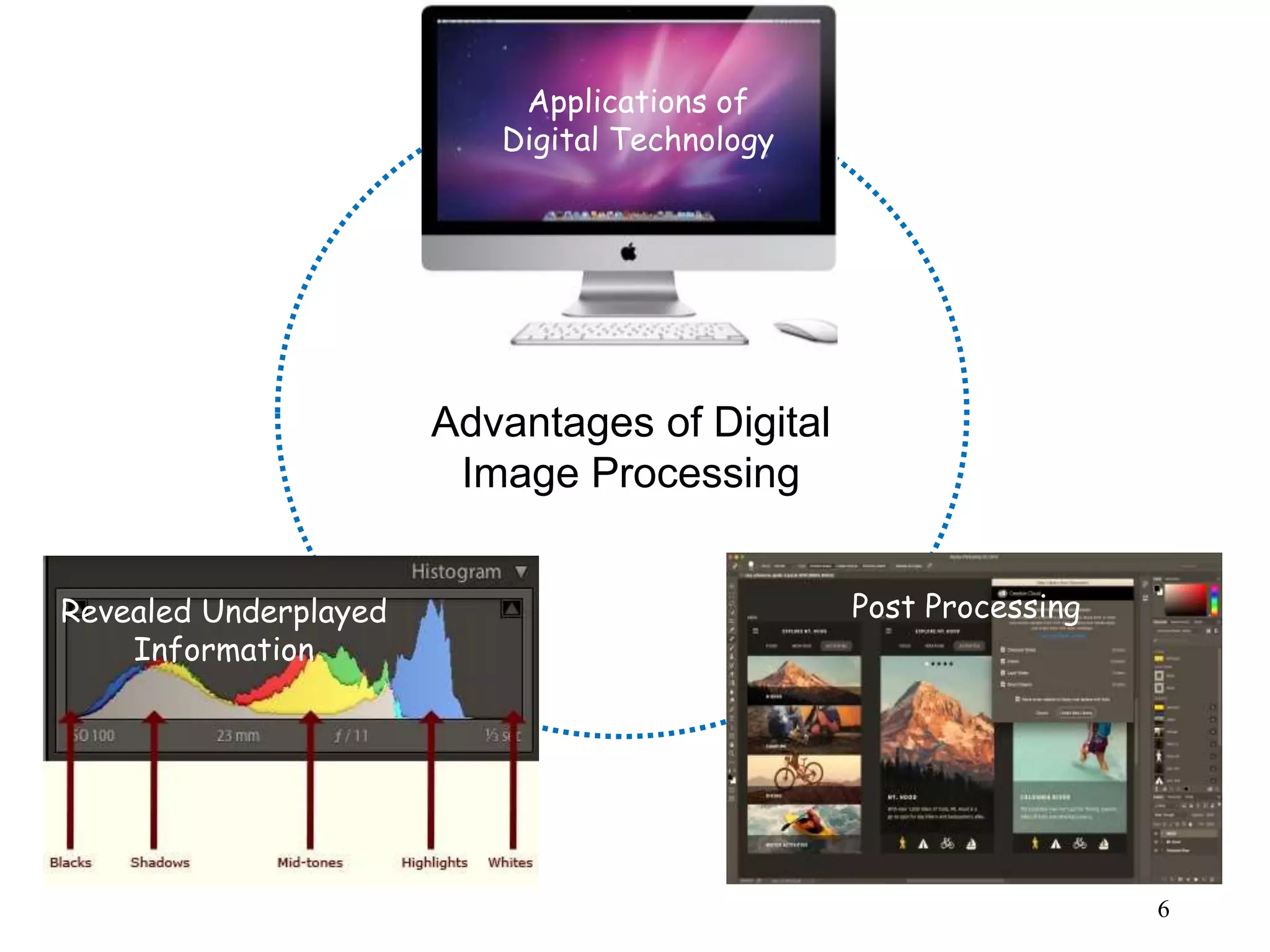
Different levels of image processing: low, mid, and high-level transformations with outputs and post-processing advantages.
Evolution of DIP from the 1920s to present: advancements due to technological developments and early applications in medical imaging.
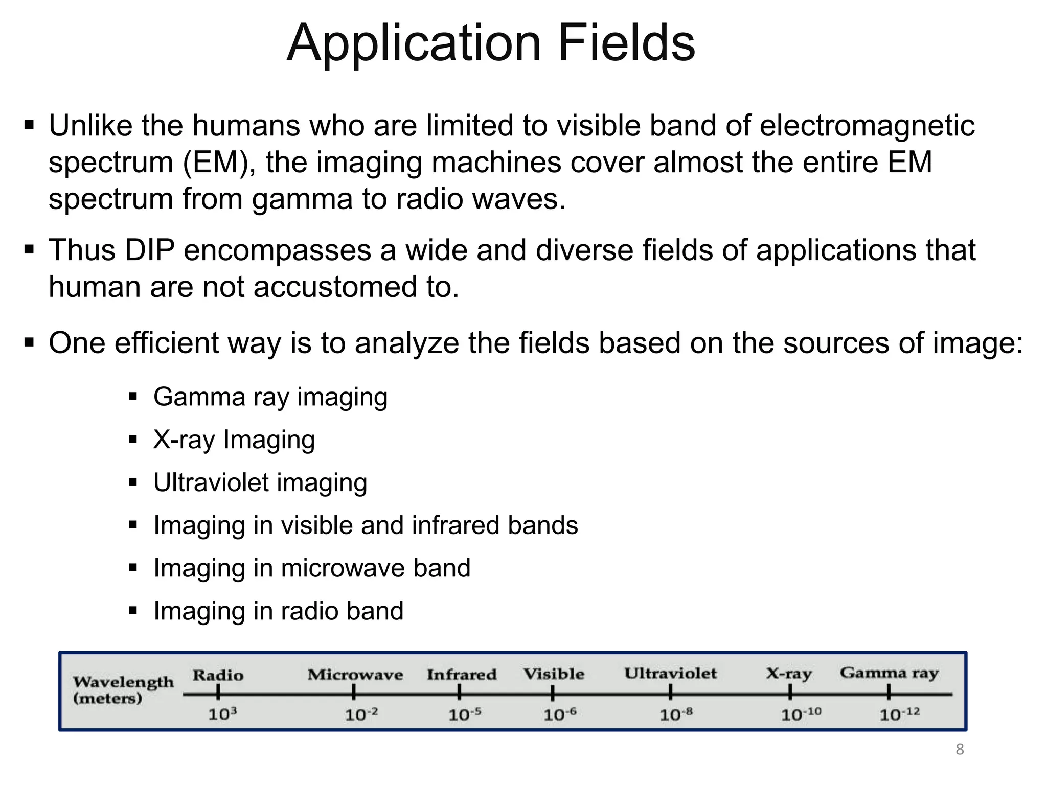
DIP's extensive applications across various fields by utilizing the electromagnetic spectrum, enhancing capabilities beyond human vision.
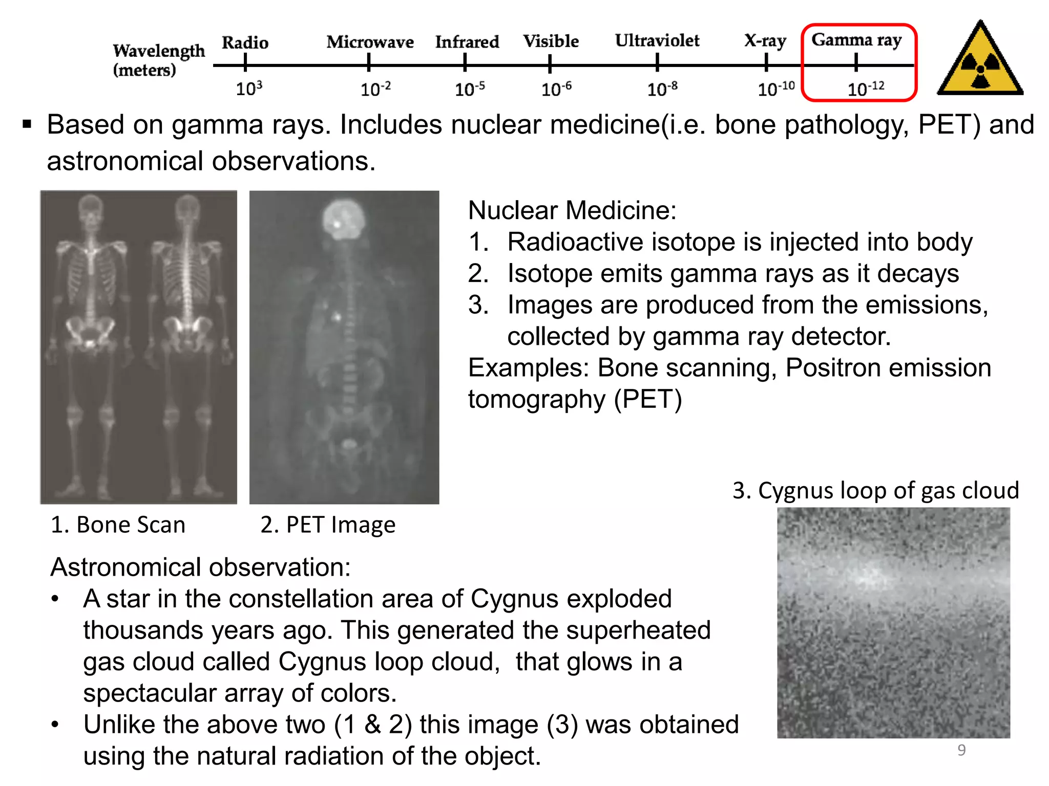
Applications of gamma ray imaging in nuclear medicine and astronomical observations, including bone pathology and PET scans.
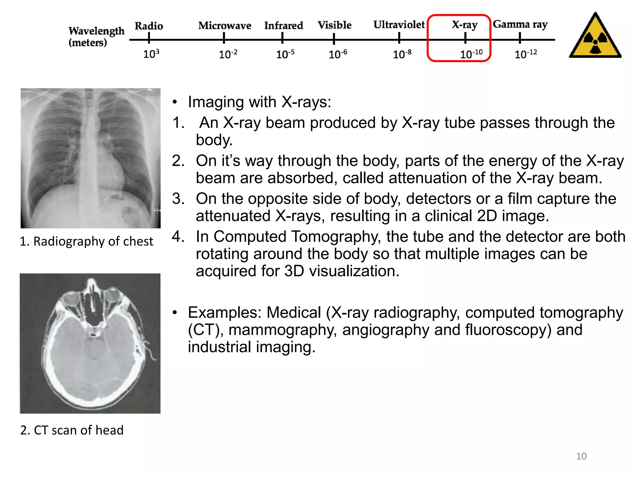
Explains X-ray imaging processes and its applications in medical diagnostics (radiography, CT scans) and industrial imaging.
Applications of ultraviolet imaging in lithography, industrial inspections, fluorescence microscopy, and biological imaging.
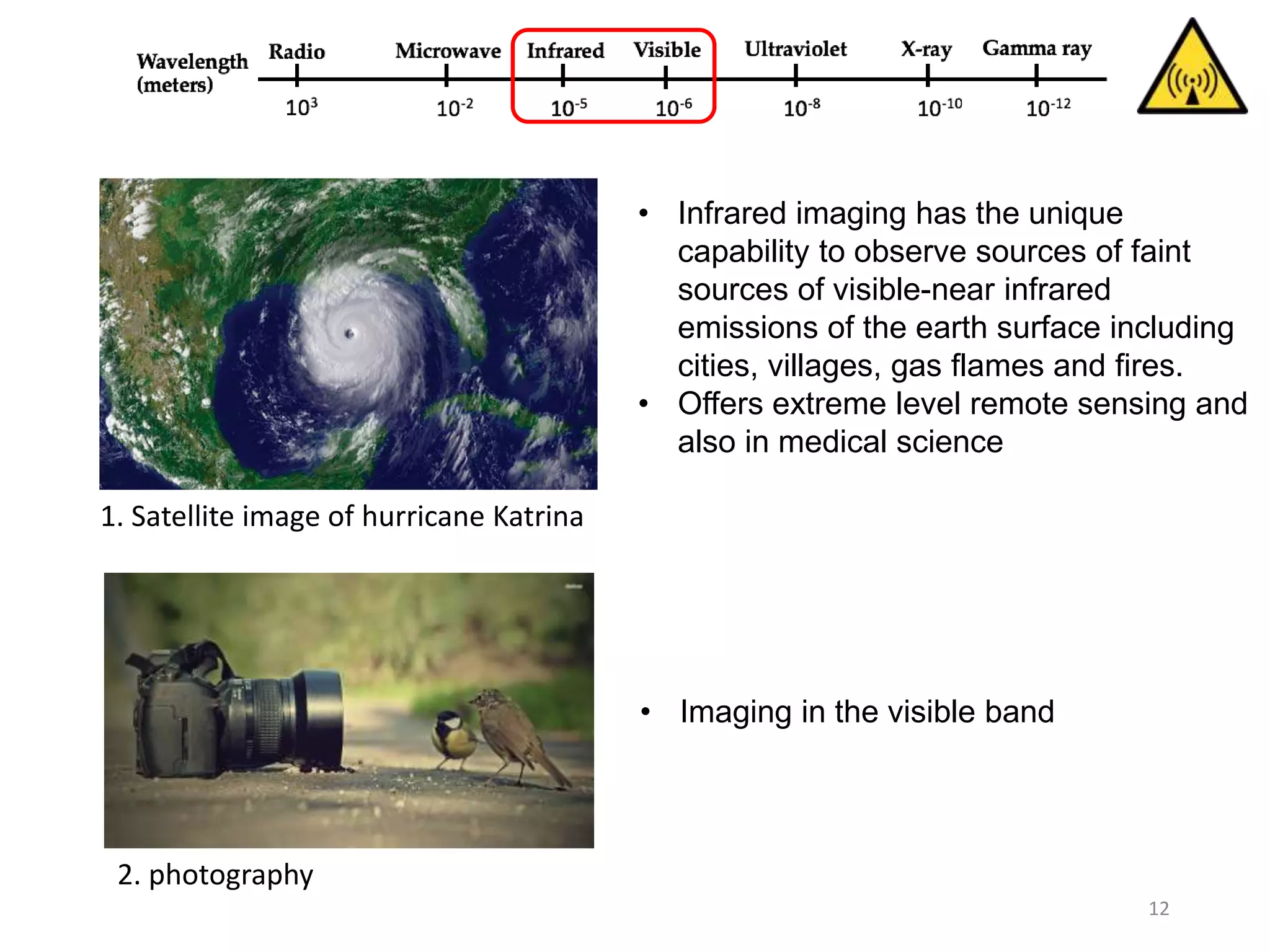
Infrared imaging for remote sensing of faint emissions from the Earth and medical applications, including satellite images.
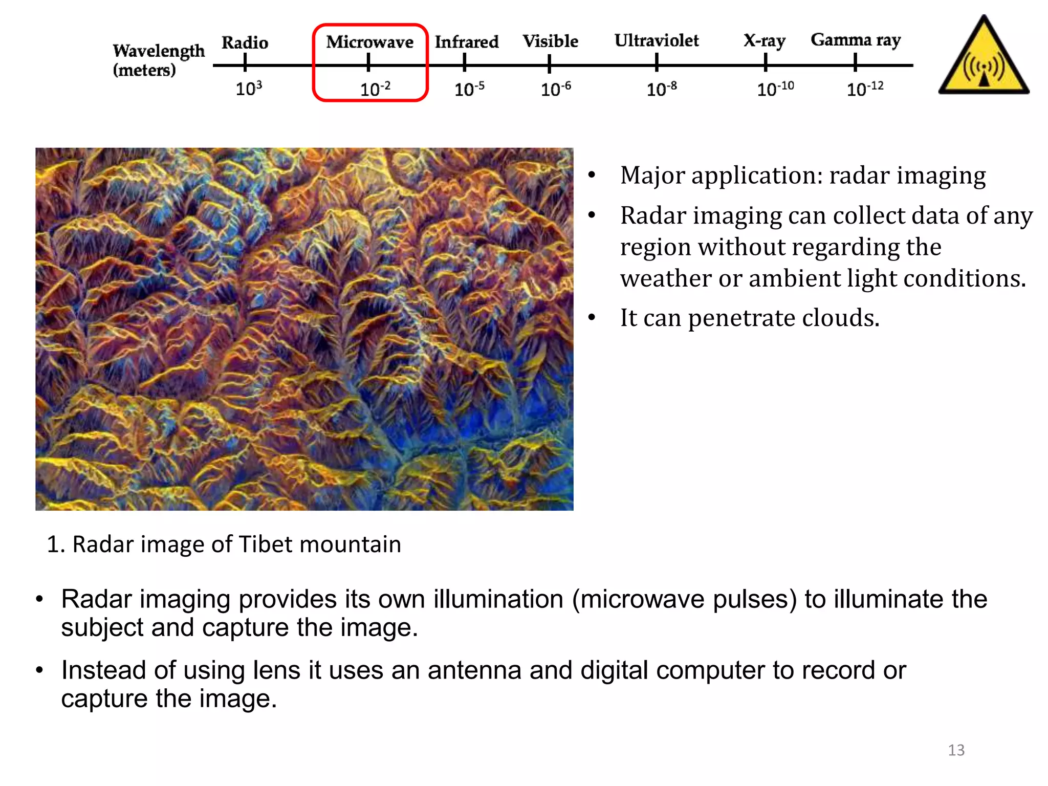
Overview of radar imaging using microwave pulses for capturing images with applications in various conditions.
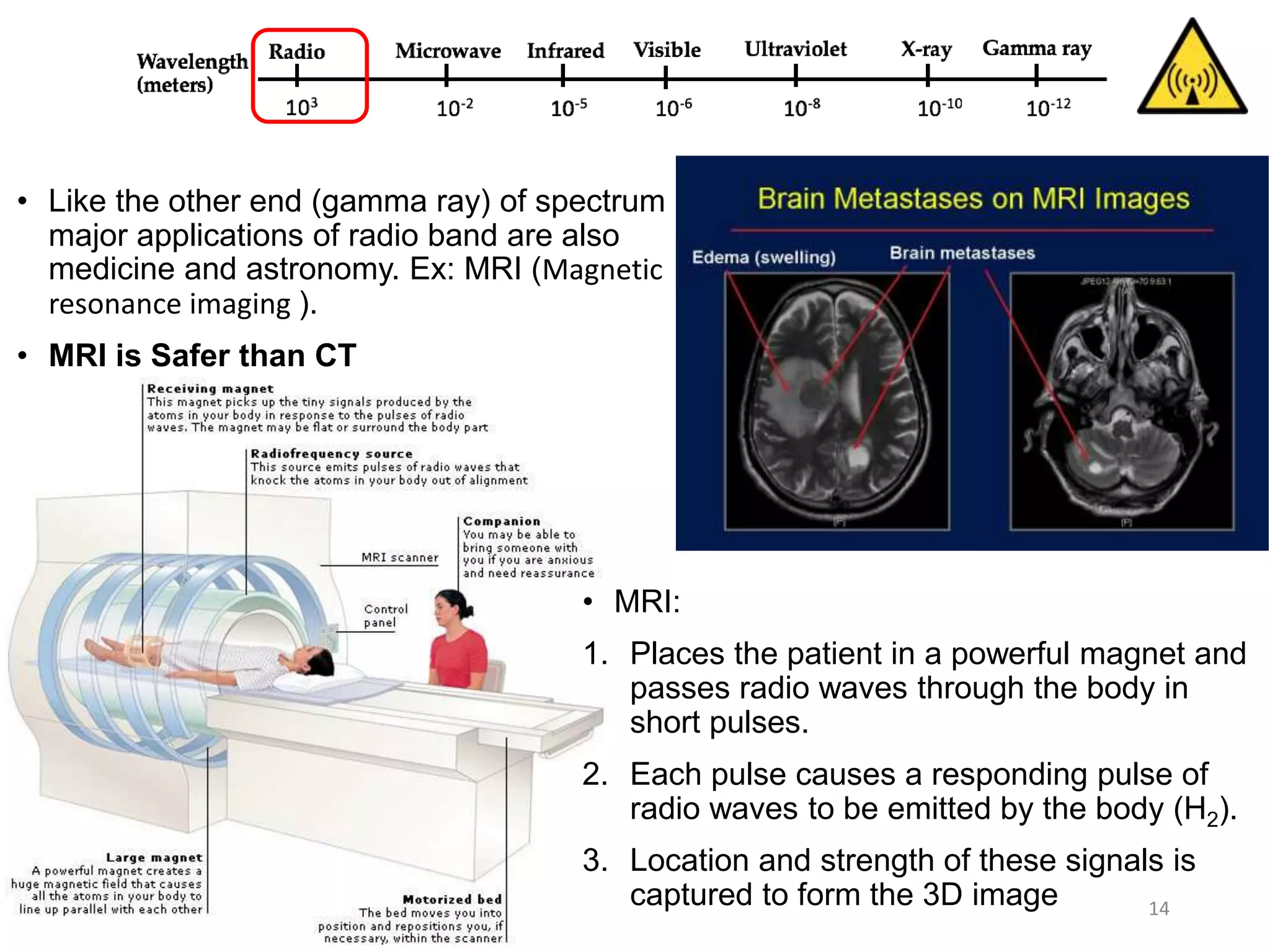
Applications of radio band imaging, focusing on MRI technology, its safety, and the mechanism of obtaining 3D images.
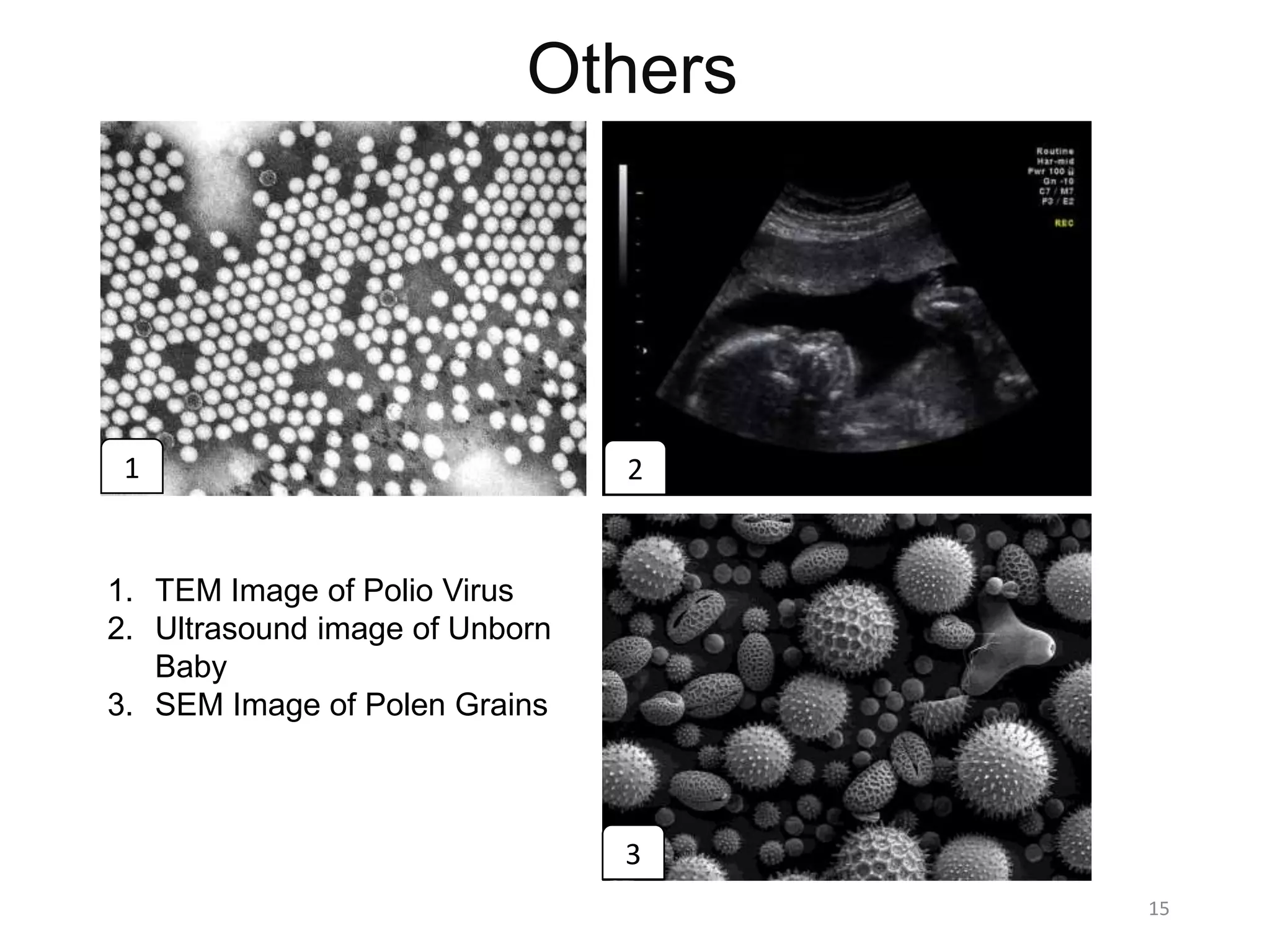
Additional imaging techniques including TEM images, ultrasound, and SEM images of biological samples.
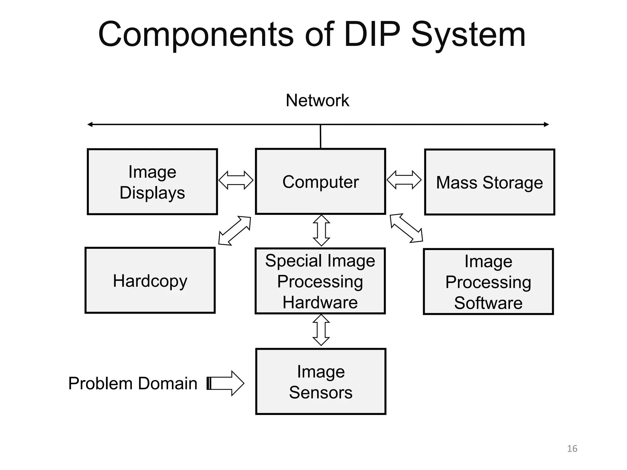
The essential components of a Digital Image Processing system including software, hardware, and image sensors.
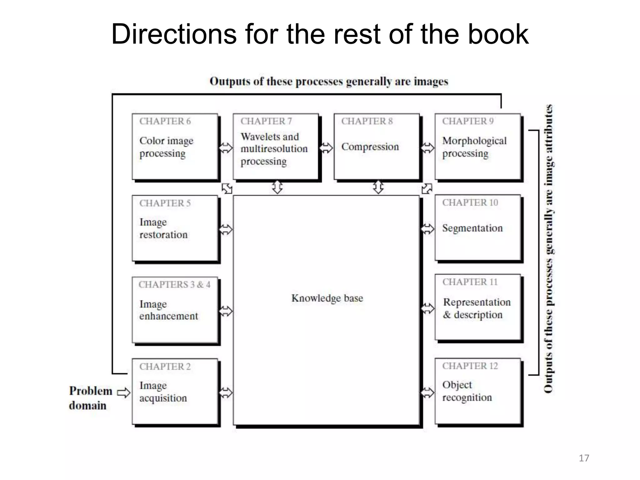
Guidance on the structure and contents for the continuation of the book, setting directions for further learning.
Chapter 1: Introduction
13November 2016 1
Hossain Md Shakhawat
Department of Information Processing
Tokyo Institute of Technology
Digital Image Processing -3rd Edition by Rafael C.
Gonzalez, Richard E. Woods
One picture is worth more than ten thousand words
2.
Objectives of thechapter
Introduction to Digital image processing (DIP)
Define the scope of DIP
Historical background
Introduce the application areas
Introduce the principle approaches of DIP
Components of image processing
Provide directions to the book
2
3.
What is Image?
Mathematically, Image is a two dimensional function f(x,y) where the x and
y are spatial co-ordinates and the amplitude of function “ f ” at any pair of
co-ordinates (x,y) is called the intensity of the image at that point.
3
Analog Image: when x, y and the amplitude
values of f are continuous quantities
Digital Image: when x, y and the amplitude
values of f are all finite and discrete
quantities.
Digital image is composed of finite number of elements called pixels,
each of which has a particular location and intensity value.
4.
Digital Image Processing
DIP is the processing of digital image in a digital manner meaning that
is using a digital device like digital computer.
Two major application areas:
1. Improvement of pictorial information for human interpretation.
2. Processing of image data for storage, transmission and
representation for autonomous machine perception
4
Digital Image Digital Computer
+
Digital Image
Processing
5.
Level of ImageProcessing
5
Image to image transformation
Low
Level
Image to attribute transformation
Mid Level
Attribute to image transformation
High Level
Information
about
Attributes
Input Process Output
Origin and Evolutionof DIP
DIP technology evolved with the advancement in digital computers
1920 -> Bartline cable system reduced the time for transmission from week to hours
1921 -> pictures were produced from a coded tape by telegraph printers
1922 -> Improvements in the reproduction system increased visual quality
1929 -> Number of gray levels increased to 15 from 5
1940 -> Invention of modern digital computer
1940 to 1960 -> Development of transistors, IC, programming language, operating
system and microprocessor made the computer efficient enough for DIP.
1960 -> First use of computer to correct images of moon
1970 -> Early applications in medical imaging
1980 to till date -> Enabled the modality of image analysis and computer vision
7
Pictures were sent using submarine cable for news
8.
Application Fields
Unlikethe humans who are limited to visible band of electromagnetic
spectrum (EM), the imaging machines cover almost the entire EM
spectrum from gamma to radio waves.
Thus DIP encompasses a wide and diverse fields of applications that
human are not accustomed to.
One efficient way is to analyze the fields based on the sources of image:
Gamma ray imaging
X-ray Imaging
Ultraviolet imaging
Imaging in visible and infrared bands
Imaging in microwave band
Imaging in radio band
8
9.
Based ongamma rays. Includes nuclear medicine(i.e. bone pathology, PET) and
astronomical observations.
9
Nuclear Medicine:
1. Radioactive isotope is injected into body
2. Isotope emits gamma rays as it decays
3. Images are produced from the emissions,
collected by gamma ray detector.
Examples: Bone scanning, Positron emission
tomography (PET)
1. Bone Scan 2. PET Image
Astronomical observation:
• A star in the constellation area of Cygnus exploded
thousands years ago. This generated the superheated
gas cloud called Cygnus loop cloud, that glows in a
spectacular array of colors.
• Unlike the above two (1 & 2) this image (3) was obtained
using the natural radiation of the object.
3. Cygnus loop of gas cloud
10.
10
• Imaging withX-rays:
1. An X-ray beam produced by X-ray tube passes through the
body.
2. On it’s way through the body, parts of the energy of the X-ray
beam are absorbed, called attenuation of the X-ray beam.
3. On the opposite side of body, detectors or a film capture the
attenuated X-rays, resulting in a clinical 2D image.
4. In Computed Tomography, the tube and the detector are both
rotating around the body so that multiple images can be
acquired for 3D visualization.
• Examples: Medical (X-ray radiography, computed tomography
(CT), mammography, angiography and fluoroscopy) and
industrial imaging.
1. Radiography of chest
2. CT scan of head
11.
11
• The ultravioletlight is not visible but it offers
a wide area of applications: lithography,
industrial inspection, fluorescence
microscopy, lasers, biological imaging and
astronomical observations.
1. Smut Corn Detection
Left: Normal Corn Right: Smut Corn
2. Mouse Brain Tissue Section
[ Source: http://www.microscopyu.com/galleries/fluorescence/index.html ]
12.
12
• Infrared imaginghas the unique
capability to observe sources of faint
sources of visible-near infrared
emissions of the earth surface including
cities, villages, gas flames and fires.
• Offers extreme level remote sensing and
also in medical science
1. Satellite image of hurricane Katrina
2. photography
• Imaging in the visible band
13.
13
• Radar imagingprovides its own illumination (microwave pulses) to illuminate the
subject and capture the image.
• Instead of using lens it uses an antenna and digital computer to record or
capture the image.
• Major application: radar imaging
• Radar imaging can collect data of any
region without regarding the
weather or ambient light conditions.
• It can penetrate clouds.
1. Radar image of Tibet mountain
14.
14
• Like theother end (gamma ray) of spectrum
major applications of radio band are also
medicine and astronomy. Ex: MRI (Magnetic
resonance imaging ).
• MRI is Safer than CT
• MRI:
1. Places the patient in a powerful magnet and
passes radio waves through the body in
short pulses.
2. Each pulse causes a responding pulse of
radio waves to be emitted by the body (H2).
3. Location and strength of these signals is
captured to form the 3D image
15.
Others
15
1. TEM Imageof Polio Virus
2. Ultrasound image of Unborn
Baby
3. SEM Image of Polen Grains
1 2
3
16.
Components of DIPSystem
16
Image
Displays
Computer Mass Storage
Hardcopy
Special Image
Processing
Hardware
Image
Processing
Software
Image
Sensors
Network
Problem Domain