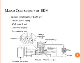
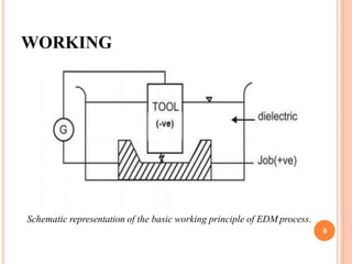
ELECTRO DISCHARGE
MACHINING (EDM)
D.PALANI KUMAR,
Assistant Prof. / Mech. Engg.,
Kamaraj College of Engg. & Tech.
Virudhunagar.
INTRODUCTION
 Electro Discharge Machining (EDM) is an electro-thermal non-
traditional machining process, where electrical energy is used to
generate electrical spark and material removal mainly occurs due to
thermal energy of the spark.
 EDM is mainly used to machine difficult-to-machine materials and high
strength temperature resistant alloys.
 EDM can be used to machine difficult geometries in small batches or
even on job-shop basis.
 Work material to be machined by EDM has to be electrically
conductive. 2
MAJOR COMPONENTS OF EDM
The main components of EDM are
Electric power supply
Work piece & tool
Dielectric medium
Servo control unit.
3
WORKING
 In EDM, a potential difference is applied between the tool and work piece.
 Both the tool and the work material are to be conductors of electricity.
 The tool and the work material are immersed in a dielectric medium.
 Dielectric Medium-kerosene or deionised water.
 Gap is maintained between the tool and the work piece.
 Depending upon the applied potential difference and the gap between the
tool and work piece, an electric field would be established.
4
WORKING (CONT..,)
 Tool is connected to the negative terminal of the generator and the work
piece is connected to positive terminal.
 As the electric field is established between the tool and the job, the free
electrons on the tool are subjected to electrostatic forces
 “cold emission”- the work function or the bonding energy of the electrons
is less, electrons would be emitted from the tool (assuming it to be
connected to the negative terminal).
 Such emission of electrons are called or termed as cold emission.
5
WORKING
Schematic representation of the basic working principle of EDM process.
6
WORKING (CONT..,)
 The “cold emitted” electrons are then accelerated towards the job
through the dielectric medium, as they gain velocity and energy, and
start moving towards the job, there would be collisions between the
electrons and dielectric molecules. Such collision may result in
ionization of the dielectric molecule.
 As the electrons get accelerated, more positive ions and electrons
would get generated due to collisions.
 This cyclic process would increase the concentration of electrons
and ions in the dielectric medium between the tool and the job at the
spark gap. 7
WORKING (CONT..,)
 The concentration would be so high that the matter existing in that
channel could be characterized as “plasma”.
8
WORKING (CONT..,)
 The electrical resistance of such plasma channel would be very less.
 Thus all of a sudden, a large number of electrons will flow from
tool to job and ions from job to tool.
 This is called avalanche motion of electrons.
 Such movement of electrons and ions can be visually seen as a
spark.
 Thus the electrical energy is dissipated as the thermal energy of the
spark.
 The high speed electrons then impinge on the job and ions onthe
tool.
 The kinetic energy of the electrons and ions on impact with the
surface of the job and tool respectively would be converted into
thermal energy or heat flux.
9
WORKING (CONT..,)
 Such intense localized heat flux leads to extreme instantaneous
confined rise in temperature which would be in excess of 10,000oC.
 Such localized extreme rise in temperature leads to material removal.
 Material removal occurs due to instant vaporization of the material as
well as due to melting.
 The molten metal is not removed completely but only partially.
 As the potential difference is withdrawn, the plasma channel is no
longer sustained. As the plasma channel collapse, it generates pressure
or shock waves, which evacuates the molten material forming a crater
of removed material around the site of the spark. 10
WORKING (CONT..,)
 Upon withdrawal of potential difference, plasma channel collapses.
 This ultimately creates compression shock waves on the electrode surface.
 Particularly at high spots on work piece surface, which are closest to the
tool.
 This evacuates molten material and forms a crater around the site of the
spark.
 The whole sequence of operation occurs within a few microseconds.
11
SUMMARY
 The material removal in EDM mainly occurs due to formation of shock waves
as the plasma channel collapse owing to discontinuation of applied potential
difference
 Generally the work piece is made positive and the tool negative.
 Hence, the electrons strike the job leading to crater formation due to high
temperature and melting and material removal.
 Similarly, the positive ions impinge on the tool leading to tool wear.
 The generator is used to apply voltage pulses between the tool and job.
 A constant voltage is not applied. Only sparking is desired rather thanarcing.
 Arcing leads to localized material removal at a particular point whereas sparks
get distributed all over the tool surface leading to uniform material removal. 12
ELECTRODE
 Electrode material should be such that it would not undergomuch
tool wear when it is impinged by positive ions.
 Thus the localized temperature rise has to be less by properly
choosing its properties or even when temperature increases, there
would be less melting.
 High electrical conductivity – electrons are cold emitted more easily
and there is less bulk electrical heating
 High thermal conductivity – for the same heat load, the local
temperature rise would be less due to faster heat conducted to the
bulk of the tool and thus less tool wear 13
14
 Higher density – for the same heat load and same tool wear by weight there
would be less volume removal or tool wear and thus less dimensional loss
or inaccuracy .
 High melting point – high melting point leads to less tool wear due to less
tool material melting for the same heat load
 Easy manufacturability
 Cost – cheap
Recommended Electrode materials:
 Graphite
 Electrolytic oxygen free copper
 Tellurium copper – 99% Cu + 0.5% tellurium
 Brass
DIELECTRIC
 Material removal mainly occurs due to thermal evaporation and melting.
 As thermal processing is required to be carried out in absence of oxygen so that
the process can be controlled and oxidation avoided.
 Oxidation often leads to poor surface conductivity (electrical) of the workpiece
hindering further machining .
 Dielectric fluid should provide an oxygen free machining environment.
 Further it should have enough strong dielectric resistance so that it does not
breakdown electrically too easily.
 But at the same time, it should ionize when electrons collide with its molecule.
 Moreover, during sparking it should be thermally resistant as well.
 Generally kerosene and deionised water is used as dielectric fluid in EDM.
15
DIELECTRIC
 Tap water cannot be used as it ionizes too early and thus breakdown due to
presence of salts as impurities occur.
 Dielectric medium is generally flushed around the spark zone.
 It is also applied through the tool to achieve efficient removal of molten
material.
Three important functions of a dielectric medium in EDM:
1. Insulates the gap between the tool and work, thus preventing a spark to
form until the gap voltage are correct.
2. Cools the electrode, workpiece and solidifies the molten metal particles.
3. Flushes the metal particles out of the working gap to maintain ideal
cutting conditions, increase metal removal rate. 16
DIELECTRIC
 It must be filtered and circulated at constant pressure
 The main requirements of the EDM dielectric fluids are adequate
viscosity, high flash point, good oxidation stability, minimum odor,
low cost, and good electrical discharge efficiency.
 For most EDM operations kerosene is used with certain additives that
prevent gas bubbles and de-odoring.
 Silicon fluids and a mixture of these fluids with petroleum oils have
given excellent results.
 Other dielectric fluids with a varying degree of success include
aqueous solutions of ethylene glycol, water in emulsions, and distilled
water.
17
POWER GENERATOR
Different power generators are used in EDM and some are
listed below
 Resistance-capacitance type (RC type) Relaxation generator
 Rotary impulse type generator
 Electronic pulse generator
 Hybrid EDM generator
18
RESISTANCE-CAPACITIVE (RC) TYPE
RELAXATION GENERATOR
19
RC TYPE RELAXATION GENERATOR
 The capacitor is charged from a DC source.
 As long as the voltage in the capacitor is not reaching the
breakdown voltage of the dielectric medium under the prevailing
machining condition, capacitor would continue to charge.
 Once the breakdown voltage is reached the capacitor would start
discharging and a spark would be established between the tool and
workpiece leading to machining.
 Such discharging would continue as long as the spark can be
sustained. Once the voltage becomes too low to sustain the spark,
the charging of the capacitor would continue. 20
21
Thus at any instant charging current, ic can be given as:
where,
Ic = charging current
Id =discharging current
Vo= open circuit voltage
Rc= charging resistance
C = capacitance
Vc= instantaneous capacitor voltage during
charging
The discharging or the machining current Id is given by
22
 For maximum power dissipation in RC type EDM generator
Vc
* = 0.716Vo.
The discharging time or machining time or on time can be
expressed as
23
∴Frequency of operation, f
Total energy discharged through spark gap
Rotary impulse generator with rectifier
Electronic Pulse Generator
Hybrid Electronic Pulse Generator
24
PROCESS PARAMETERS
25
The waveform is characterized by the
o The open circuit voltage - Vo
o The working voltage -Vw
o The maximum current - Io
oThe pulse on time – the duration for which the voltage pulse is
applied - ton
o The pulse off time - toff
o The gap between the workpiece and the tool – spark gap - δ
o The polarity – straight polarity – tool (-ve)
o The dielectric medium
o External flushing through the spark gap.
26
EDM – MATERIAL REMOVAL RATE
27
PROCESS PARAMETERS (CONTD..,)
ngle spark is
 Material removal rate:
28
 material removal in a single spark can be expressed as
T
ool
Spark
 the energy content of a si
Crater
PROCESS PARAMETERS (CONTD..,)
29
Taper cut & over cut Prevention of Taper Cut
Insulated
EDM – CHARACTERISTICS
 Can be used to machine any work material if it is electrically
conductive.
 Capacitor discharge is between 50 and 380 V
 Dielectric slurry is forced through this gap at a pressure of 2
kgf/cm2 or lesser.
 A gap, known as SPARK GAP in the range, from 0.005 mm to
0.05 mm is maintained between the work piece and the tool.
 The current density in the discharge of the channel is of the order
of 10000 A/cm2 and power density is nearly 500 MW/cm2.
 MRR depends on thermal properties (job) rather than its strength,
hardness etc.
 The volume of the material removed per spark discharge is
typically in the range of (1/1,000,000) to (1/10,000) mm3.
30
EDM – CHARACTERISTICS (CONTD..,)
 In EDM, geometry of tool - positive impression of hole or
geometric feature.
 Tool wear once again depends on the thermal properties of tool
material.
 Local temperature rise is rather high, but there is not enough heat
diffusion (very small pulse on time) and thus HAZ is limited to 2 –
4 μm.
 Rapid heating and cooling leads to surface hardening which may
be desirable in some applications.
 Tolerance value of + 0.05 mm could be easily achieved by EDM.
 Best surface finish that can be economically achieved on steel is
0.40 m
31
APPLICATIONS
 Drilling of micro-holes, thread cutting, helical profilemilling,
rotary forming, and curved hole drilling.
 Delicate work piece like copper parts can be produced by EDM.
 Can be applied to all electrically conducting metals and alloys
irrespective of their melting points, hardness, toughness, or
brittleness.
 Other applications: deep, small-dia holes using tungsten wire as
tool, narrow slots, cooling holes in super alloy turbine blades,and
various intricate shapes.
 EDM can be economically employed for extremely hardened work
piece.
 Since there is no mechanical stress present (no physical contact),
fragile and slender work places can be machined without distortion.
 Hard and corrosion resistant surfaces, essentially needed fordie
making, can be developed
32
ADVANTAGES
Some of the advantages of EDM include machining of:
 Complex shapes that would otherwise be difficult to producewith
conventional cutting tools.
 Extremely hard material to very close tolerances.
 Very small work pieces where conventional cutting tools may
damage the part from excess cutting tool pressure.
 There is no direct contact between tool and work piece. Therefore
delicate sections and weak materials can be machined without any
distortion.
 A good surface finish can beobtained. 33
DISADVANTAGES
Some of the disadvantages of EDM include:
 The slow rate of material removal.
 For economic production, the surface finish specified should notbe
too fine.
 The additional time and cost used for creating electrodesfor
ram/sinker EDM.
 Reproducing sharp corners on the workpiece is difficult dueto
electrode wear.
 Power consumption is high.
 "Overcut" is formed.
 Excessive tool wear occurs during machining.
 Electrically non-conductive materials can be machined only with
specific set-up of the process 34
35

ELECTRO_DISCHARGE_MACHINING_EDM.pptx

  • 1.
    ELECTRO DISCHARGE MACHINING (EDM) D.PALANIKUMAR, Assistant Prof. / Mech. Engg., Kamaraj College of Engg. & Tech. Virudhunagar.
  • 2.
    INTRODUCTION  Electro DischargeMachining (EDM) is an electro-thermal non- traditional machining process, where electrical energy is used to generate electrical spark and material removal mainly occurs due to thermal energy of the spark.  EDM is mainly used to machine difficult-to-machine materials and high strength temperature resistant alloys.  EDM can be used to machine difficult geometries in small batches or even on job-shop basis.  Work material to be machined by EDM has to be electrically conductive. 2
  • 3.
    MAJOR COMPONENTS OFEDM The main components of EDM are Electric power supply Work piece & tool Dielectric medium Servo control unit. 3
  • 4.
    WORKING  In EDM,a potential difference is applied between the tool and work piece.  Both the tool and the work material are to be conductors of electricity.  The tool and the work material are immersed in a dielectric medium.  Dielectric Medium-kerosene or deionised water.  Gap is maintained between the tool and the work piece.  Depending upon the applied potential difference and the gap between the tool and work piece, an electric field would be established. 4
  • 5.
    WORKING (CONT..,)  Toolis connected to the negative terminal of the generator and the work piece is connected to positive terminal.  As the electric field is established between the tool and the job, the free electrons on the tool are subjected to electrostatic forces  “cold emission”- the work function or the bonding energy of the electrons is less, electrons would be emitted from the tool (assuming it to be connected to the negative terminal).  Such emission of electrons are called or termed as cold emission. 5
  • 6.
    WORKING Schematic representation ofthe basic working principle of EDM process. 6
  • 7.
    WORKING (CONT..,)  The“cold emitted” electrons are then accelerated towards the job through the dielectric medium, as they gain velocity and energy, and start moving towards the job, there would be collisions between the electrons and dielectric molecules. Such collision may result in ionization of the dielectric molecule.  As the electrons get accelerated, more positive ions and electrons would get generated due to collisions.  This cyclic process would increase the concentration of electrons and ions in the dielectric medium between the tool and the job at the spark gap. 7
  • 8.
    WORKING (CONT..,)  Theconcentration would be so high that the matter existing in that channel could be characterized as “plasma”. 8
  • 9.
    WORKING (CONT..,)  Theelectrical resistance of such plasma channel would be very less.  Thus all of a sudden, a large number of electrons will flow from tool to job and ions from job to tool.  This is called avalanche motion of electrons.  Such movement of electrons and ions can be visually seen as a spark.  Thus the electrical energy is dissipated as the thermal energy of the spark.  The high speed electrons then impinge on the job and ions onthe tool.  The kinetic energy of the electrons and ions on impact with the surface of the job and tool respectively would be converted into thermal energy or heat flux. 9
  • 10.
    WORKING (CONT..,)  Suchintense localized heat flux leads to extreme instantaneous confined rise in temperature which would be in excess of 10,000oC.  Such localized extreme rise in temperature leads to material removal.  Material removal occurs due to instant vaporization of the material as well as due to melting.  The molten metal is not removed completely but only partially.  As the potential difference is withdrawn, the plasma channel is no longer sustained. As the plasma channel collapse, it generates pressure or shock waves, which evacuates the molten material forming a crater of removed material around the site of the spark. 10
  • 11.
    WORKING (CONT..,)  Uponwithdrawal of potential difference, plasma channel collapses.  This ultimately creates compression shock waves on the electrode surface.  Particularly at high spots on work piece surface, which are closest to the tool.  This evacuates molten material and forms a crater around the site of the spark.  The whole sequence of operation occurs within a few microseconds. 11
  • 12.
    SUMMARY  The materialremoval in EDM mainly occurs due to formation of shock waves as the plasma channel collapse owing to discontinuation of applied potential difference  Generally the work piece is made positive and the tool negative.  Hence, the electrons strike the job leading to crater formation due to high temperature and melting and material removal.  Similarly, the positive ions impinge on the tool leading to tool wear.  The generator is used to apply voltage pulses between the tool and job.  A constant voltage is not applied. Only sparking is desired rather thanarcing.  Arcing leads to localized material removal at a particular point whereas sparks get distributed all over the tool surface leading to uniform material removal. 12
  • 13.
    ELECTRODE  Electrode materialshould be such that it would not undergomuch tool wear when it is impinged by positive ions.  Thus the localized temperature rise has to be less by properly choosing its properties or even when temperature increases, there would be less melting.  High electrical conductivity – electrons are cold emitted more easily and there is less bulk electrical heating  High thermal conductivity – for the same heat load, the local temperature rise would be less due to faster heat conducted to the bulk of the tool and thus less tool wear 13
  • 14.
    14  Higher density– for the same heat load and same tool wear by weight there would be less volume removal or tool wear and thus less dimensional loss or inaccuracy .  High melting point – high melting point leads to less tool wear due to less tool material melting for the same heat load  Easy manufacturability  Cost – cheap Recommended Electrode materials:  Graphite  Electrolytic oxygen free copper  Tellurium copper – 99% Cu + 0.5% tellurium  Brass
  • 15.
    DIELECTRIC  Material removalmainly occurs due to thermal evaporation and melting.  As thermal processing is required to be carried out in absence of oxygen so that the process can be controlled and oxidation avoided.  Oxidation often leads to poor surface conductivity (electrical) of the workpiece hindering further machining .  Dielectric fluid should provide an oxygen free machining environment.  Further it should have enough strong dielectric resistance so that it does not breakdown electrically too easily.  But at the same time, it should ionize when electrons collide with its molecule.  Moreover, during sparking it should be thermally resistant as well.  Generally kerosene and deionised water is used as dielectric fluid in EDM. 15
  • 16.
    DIELECTRIC  Tap watercannot be used as it ionizes too early and thus breakdown due to presence of salts as impurities occur.  Dielectric medium is generally flushed around the spark zone.  It is also applied through the tool to achieve efficient removal of molten material. Three important functions of a dielectric medium in EDM: 1. Insulates the gap between the tool and work, thus preventing a spark to form until the gap voltage are correct. 2. Cools the electrode, workpiece and solidifies the molten metal particles. 3. Flushes the metal particles out of the working gap to maintain ideal cutting conditions, increase metal removal rate. 16
  • 17.
    DIELECTRIC  It mustbe filtered and circulated at constant pressure  The main requirements of the EDM dielectric fluids are adequate viscosity, high flash point, good oxidation stability, minimum odor, low cost, and good electrical discharge efficiency.  For most EDM operations kerosene is used with certain additives that prevent gas bubbles and de-odoring.  Silicon fluids and a mixture of these fluids with petroleum oils have given excellent results.  Other dielectric fluids with a varying degree of success include aqueous solutions of ethylene glycol, water in emulsions, and distilled water. 17
  • 18.
    POWER GENERATOR Different powergenerators are used in EDM and some are listed below  Resistance-capacitance type (RC type) Relaxation generator  Rotary impulse type generator  Electronic pulse generator  Hybrid EDM generator 18
  • 19.
  • 20.
    RC TYPE RELAXATIONGENERATOR  The capacitor is charged from a DC source.  As long as the voltage in the capacitor is not reaching the breakdown voltage of the dielectric medium under the prevailing machining condition, capacitor would continue to charge.  Once the breakdown voltage is reached the capacitor would start discharging and a spark would be established between the tool and workpiece leading to machining.  Such discharging would continue as long as the spark can be sustained. Once the voltage becomes too low to sustain the spark, the charging of the capacitor would continue. 20
  • 21.
    21 Thus at anyinstant charging current, ic can be given as: where, Ic = charging current Id =discharging current Vo= open circuit voltage Rc= charging resistance C = capacitance Vc= instantaneous capacitor voltage during charging The discharging or the machining current Id is given by
  • 22.
    22  For maximumpower dissipation in RC type EDM generator Vc * = 0.716Vo. The discharging time or machining time or on time can be expressed as
  • 23.
    23 ∴Frequency of operation,f Total energy discharged through spark gap
  • 24.
    Rotary impulse generatorwith rectifier Electronic Pulse Generator Hybrid Electronic Pulse Generator 24
  • 25.
  • 26.
    The waveform ischaracterized by the o The open circuit voltage - Vo o The working voltage -Vw o The maximum current - Io oThe pulse on time – the duration for which the voltage pulse is applied - ton o The pulse off time - toff o The gap between the workpiece and the tool – spark gap - δ o The polarity – straight polarity – tool (-ve) o The dielectric medium o External flushing through the spark gap. 26
  • 27.
    EDM – MATERIALREMOVAL RATE 27
  • 28.
    PROCESS PARAMETERS (CONTD..,) nglespark is  Material removal rate: 28  material removal in a single spark can be expressed as T ool Spark  the energy content of a si Crater
  • 29.
    PROCESS PARAMETERS (CONTD..,) 29 Tapercut & over cut Prevention of Taper Cut Insulated
  • 30.
    EDM – CHARACTERISTICS Can be used to machine any work material if it is electrically conductive.  Capacitor discharge is between 50 and 380 V  Dielectric slurry is forced through this gap at a pressure of 2 kgf/cm2 or lesser.  A gap, known as SPARK GAP in the range, from 0.005 mm to 0.05 mm is maintained between the work piece and the tool.  The current density in the discharge of the channel is of the order of 10000 A/cm2 and power density is nearly 500 MW/cm2.  MRR depends on thermal properties (job) rather than its strength, hardness etc.  The volume of the material removed per spark discharge is typically in the range of (1/1,000,000) to (1/10,000) mm3. 30
  • 31.
    EDM – CHARACTERISTICS(CONTD..,)  In EDM, geometry of tool - positive impression of hole or geometric feature.  Tool wear once again depends on the thermal properties of tool material.  Local temperature rise is rather high, but there is not enough heat diffusion (very small pulse on time) and thus HAZ is limited to 2 – 4 μm.  Rapid heating and cooling leads to surface hardening which may be desirable in some applications.  Tolerance value of + 0.05 mm could be easily achieved by EDM.  Best surface finish that can be economically achieved on steel is 0.40 m 31
  • 32.
    APPLICATIONS  Drilling ofmicro-holes, thread cutting, helical profilemilling, rotary forming, and curved hole drilling.  Delicate work piece like copper parts can be produced by EDM.  Can be applied to all electrically conducting metals and alloys irrespective of their melting points, hardness, toughness, or brittleness.  Other applications: deep, small-dia holes using tungsten wire as tool, narrow slots, cooling holes in super alloy turbine blades,and various intricate shapes.  EDM can be economically employed for extremely hardened work piece.  Since there is no mechanical stress present (no physical contact), fragile and slender work places can be machined without distortion.  Hard and corrosion resistant surfaces, essentially needed fordie making, can be developed 32
  • 33.
    ADVANTAGES Some of theadvantages of EDM include machining of:  Complex shapes that would otherwise be difficult to producewith conventional cutting tools.  Extremely hard material to very close tolerances.  Very small work pieces where conventional cutting tools may damage the part from excess cutting tool pressure.  There is no direct contact between tool and work piece. Therefore delicate sections and weak materials can be machined without any distortion.  A good surface finish can beobtained. 33
  • 34.
    DISADVANTAGES Some of thedisadvantages of EDM include:  The slow rate of material removal.  For economic production, the surface finish specified should notbe too fine.  The additional time and cost used for creating electrodesfor ram/sinker EDM.  Reproducing sharp corners on the workpiece is difficult dueto electrode wear.  Power consumption is high.  "Overcut" is formed.  Excessive tool wear occurs during machining.  Electrically non-conductive materials can be machined only with specific set-up of the process 34
  • 35.